Chery S11 / Chery QQ. Manual - part 227
Chery QQ Maintenance Manual 465 EFI System
5
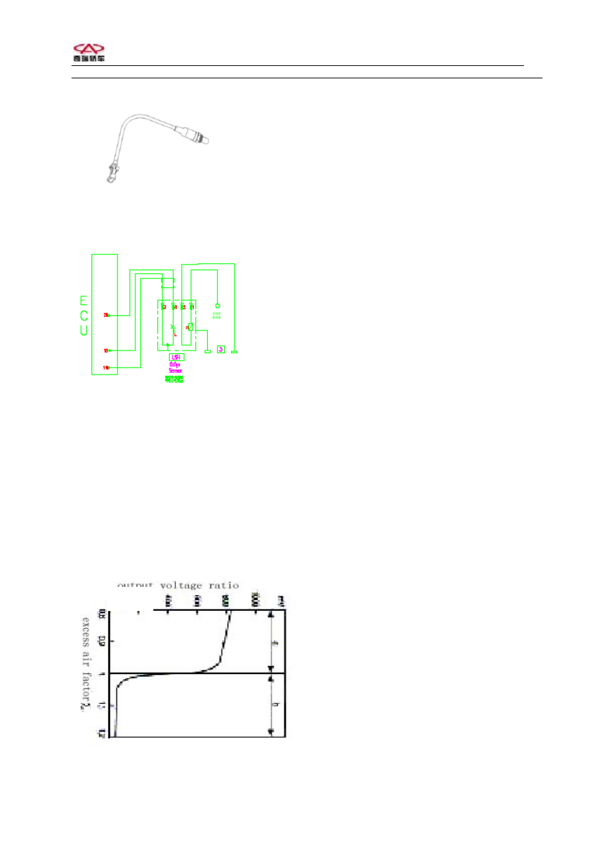
Oxygen sensor
The diagram of oxygen sensor
Oxygen sensor connects with cable. The
other end of cable is electric connector.
There is asbestos
Cover on outside.
Pins on connector:
No.1: Connect heat source (+)/white
No.2: Connect heat source (-)/white
No.3: Connect signal (-)/gray
No.4: Connect signal (+)/black
Feature curve of oxygen sensor at 600 C
6、ECU
Usage: ECU is central part of electronic
control system. Sensors supply every signal
for ECU. After calculation, ECU will
control the action of actuator such as
injector and ignition coil to control engine
operation.
Constitute: There are shield shell and PC
board in ECU. Many electronic control units
are interated on the board to control EFI
system.
Install: ECU is fixed under instrument panel
by screws. Note to insert pins vertically
during installation, otherwise it will cause
terminals getting out to influence the normal
operation of engine.
Output