Chery S11 / Chery QQ. Manual - part 228
 

  Index      Chery     Chery S11 / Chery QQ - service repair manual


Search            


Content   ..  226  227  228  229   ..


Chery S11 / Chery QQ. Manual - part 228


 Chery  QQ  Maintenance Manual                   465 EFI System


driver. When injector driver is short to battery voltage or overload, short to ground or open, 
ECU will mark malfunction position. Oxygen sensor close-loop control and self-study 
pre-control will shut off. The last self-study data is effective. After troubleshooting, 
malfunction position resumes. 


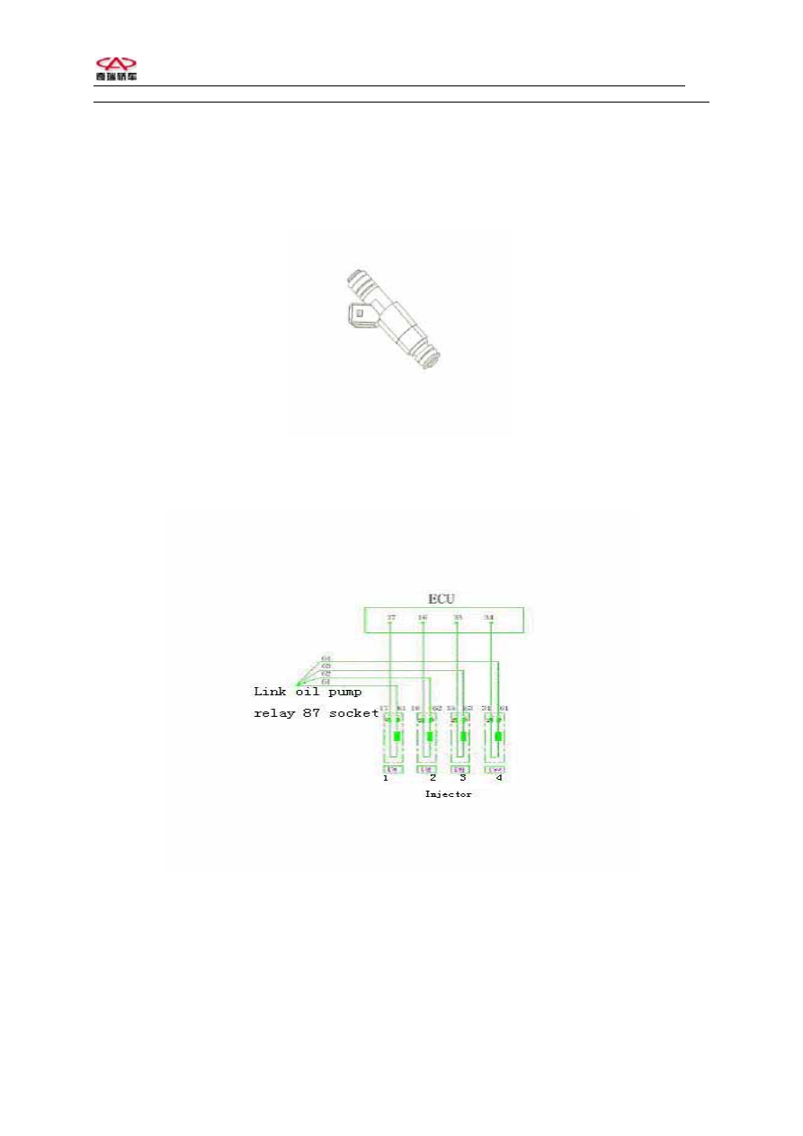
Injector 


The diagram of injector 

 
Pins: There are 2 pins on each injector. One of pins marked (+) on side of shell connects pin 
87 on pump relay, and another connects pin 17,16, 35, 34 on ECU. 


9

 Chery  QQ  Maintenance Manual                   465 EFI System


9. Step motor DLA 
Function:
 Step motor with idle actuator offers by-pass intake air channel. When throttle 
closes, air will enter engine through the channel. ECU can regulate the section of channel to 
adjust mass airflow and adjust inject fuel amount. When engine works, ECU will control step 
motor according to different working conditions to change the operation of engine. ECU 
increases or reduces the section area of by-pass channel to increase or reduce engine speed to 
realize engine close-loop control at idle. 
Constitute and principle: Step motor is a micro motor that consists of several steel stators 
and one rotor. A coil is reeled on each stator. Rotor is a permanent magnet with a nut on the 
center. All stator coils is always connected with electricity. If changing current direction in 
one coil, rotor will turn a degree. When current direction in each stator coil is changed in 
suitable order, revolutionary field is formed to run rotor in certain direction. 
Disgnosis: ECU can monitor the short or open of two coils for step motor and lights MIL. 
Engine runs at malfunction mode.   


Step motor 


The diagram of step motor 

Pins: 
PinA: Connect pin 29 on ECU. 
PinB: Connect pin 4 on ECU. 
PinC: Connect pin 26 on ECU. 
PinD: Connect pin 21 on ECU. 


10

 Chery  QQ  Maintenance Manual                   465 EFI System


10. Ignition coil ZSK-ROV 
Function: 
Ignition coil transforms low voltage on primary coil into high voltage on 
secondary coil and produces sparks through spark plug to light fuel-air mix in cylinder. 
Constitute and principle: Ignition coil consists of primary coil, secondary coil, iron core and 
shell. When battery voltage supplies on primary coil, the coil is charged. Once ECU cuts off 
the return loop of primary coil, charging stops. The high voltage is induced in secondary coil 
at same time. 
Diagnosis: ECU does not have diagnosis function for ignition coil. So if ignition coil is fault, 
DTC does not exist. It can judge if the coil works normally only by checking resistance of 
ignition coil. Usually, ignition coil produces more heat during the working, but over heat of 
coil will result in increasing for coil resistance. It will cause unstable running and 
automatically stopping work for engine. 
Primary coil: 0.47 ohms. 
Secondary coil: 8 ohms. 


Ignition coil( with distributor) 


The diagram of ignition coil( with distributor) 

Pins: There are 2 pins on low voltage side of coil. Pin marked (+) connects battery and the 
other connects ECU. 


11

 Chery  QQ  Maintenance Manual                   465 EFI System


11. Canister control valve 
Usage: 
The valve is used to control flux to clean canister. The valve is controlled by ECU 
according to engine load, lasting time and frequency of pulses. The fuel vapor in canister will 
accumulate to leak fuel for polluting environment. The function of canister solenoid is to open 
the solenoid to pass superfluous vapor into intake air pipe to be in combustion. 
Constitute an principle: The valve consists of magnetic coil, iron core and valve body. 
There is filter on inlet. Mass flow through the valve is related with the frequency of electric 
pulses that put out to control valve by ECU and with the pressure differential between inlet 
and outlet. If no pulses, canister control valve will close. ECU controls the electrify time for 
canister solenoid to indirectly control the mass flow of clearing air. 
Diagnosis: ECU does not have diagnosis function for canister control valve, but can 
diagnoses canister control valve driver. When canister control valve driver is short to battery 
voltage or over load, short to ground and open, the basic self-study of fuel metering 
close-loop control is shut off. If canister solenoid is fault, engine will be unstable idle or over 
high idle. 


Canister contorl valve 


The diagram of canister control valve TEV-2 

Pins: There 2 pins on canister control valve. One connects pin 87 on main relay and the other 
connects pin 5 on ECU. 


12


Content   ..  226  227  228  229   ..