Chery S11 / Chery QQ. Manual - part 226
 

  Index      Chery     Chery S11 / Chery QQ - service repair manual


Search            


Content   ..  224  225  226  227   ..


Chery S11 / Chery QQ. Manual - part 226


Chery  QQ  Maintenance Manual                   465 EFI System


1


Chapter 1    The principle for 

EFI and actuator

 
1.  Intake air pressure and intake 
temperature sensor 
Usage: Measure baro pressure equal or 
below 115kPa in manifold and intake air 
temperature to supply load information for 
engine. 
Constitute and pricinple:The sensor consists 
of two sensors, MAP and IAT, which 
mounted on voltage stablizer box. 
MAP: Map consists of one silicon chip that 
etched a film on the chip. There are 4 
piezoelectric resistances that consist of a 
Wiston bridge. The information processing 
circuit is also on the chip. The chip consists 
of closed reference space with a metal shell. 
The air absolute pressure in the space is 
nearly to zero. In this way, a micro 
electric-mechanic system is formed. The 
active face of the chip is endured a pressure 
nearly to zero, and MAP pressure applies on 
the back of the chip through a connecting 
pipe. The thickness of the chip is only 
several microns( um),so the change of 
MAP pressure will result the mechanical 
deform for the chip together with 4 
resistances to change their resistance. The 
voltage signal that is linearity with pressure 
is formed after processing by information 
processing circuit in the chip. 
Intake air pressure: IAT is a resistor with 
NTC. Like coolant temperature sensor, the 
resistance decreased with the temperature 
increasing. ECU in engine monitors the 
change of intake air temperature 
(corresponding in series circuit). 
Diagnosis: The open, short or wear of sensor 
could be detected by the rear electronic unit 
of MAP. 
ECU will judge the malfunction of sensor if   

the out put signal exceeds the signal outside 
the curve of output feature. For example, if 
the intake air pressure is higher than the up 
limit or lower than lower limit,ECU will 
judge that sensor is malfunction ( The intake 
air pressure is below lower limit in starting, 
but ECU can judge starting condition), 
“CHECK ENGINE”light will on at same 
time and engine will run at malfunction 
mode.  


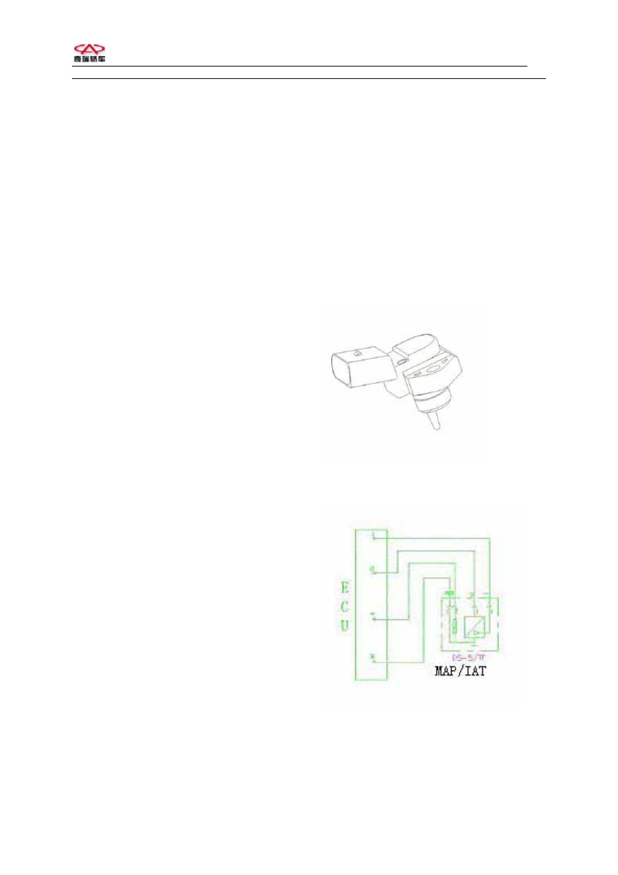
MAP/IAT 


The circuit for MAR/IAT 
Pins: No.1 Ground 
No.2 Output signal of temperature 
No.3 To 5V 


 Chery  QQ  Maintenance Manual                   465 EFI System


No.4 Output pressure signal 


The section plane of MAP/IAT 
1.  Seal 2. Stainless steel bush   
3. PCB plate 4. Sensor    5. Shell 
6. Support 7. Welding connection 
8. Felt connection   
 
2. TPS
 
Usage: TPS is used to supply Throttle angle 
signal. According to this signal, ECU will 
receive engine load signal and working 
condition signal such as starting, idle, back 
up, partial load, and full load) as well as 
acceleration and deceleration signal. 
Constitute and pricinple:TPS is a angle 
sensor with linear output. It consists of 2 arc 
slide resistors and 2 slide arms. The shaft of 
arm and throttle shaft connect to one axes. 
When running throttle, arm run together and 
slides on resistor. Putout UP as output 
voltage. So it is a angle potentiometer.   
Diagnosis: ECU check if throttle angle 
exceeds the up limit or lower limit of output 
signal. If so, ECU will judge TPS 
malfunction, engine will run at malfunction 
mode, MIL will on (Knock sensor or dirty 
will cause engine malfunction). 
Install: Screw torque for bolts: 
1.5Nm-2.5Nm 


Out view of TPS 


Diagram of TPS 

Pins: Run throttle counterclockwise (see 
from one side of sensor on shaft into 
throttle):1.Ground  2. 5V source  3. 5V 
source 
 
3. Coolant temperature sensor TF-W
 
Usage: ECT is used to supply Coolant 
temperature information for the timing and 
fuel inject pulse width control on engine 
start, idle, normal running. 
Constitute and principle: ECT is a thermal 
sense resistor with NTC. The resistance 
decreases with coolant temperature increases, 
but it is not in linearity. The resistor is 
enclosed in copper bush. The change of 
resistance is transformed into changing 
voltage to ECU by a voltage distribute 
circuit to monitor the change of water 
temperature. 
Diagnosis: When coolant temperature is 
over up limit, or below lower limit, MIL is 
on, engine run at malfunction mode. ECU 
control ignition and fuel inject according to 
set temperature. Fan runs at high speed. 
Limit data: 2.5±5%KΩ 
Hint: Screw torque: 15±2Nm 
Hint: There are 2 sensors in vehicle. One is 
single pin water temperature and supply 
water temperature signal for water temp 
meter; The other is double pins and supplies 
the temp signal to ECU. 


2

 Chery  QQ  Maintenance Manual                   465 EFI System


Diagram of ECT 


The diagram of coolant tem sensor 
Pins: There are 2 pins that could be 
inter-exchangeable. 


Coolant temp sensor 

1. Connector 2. Sleeve 3. NTC resistor 
 
4. KS 
Usage: 
Supply knock signal to ECU for 
knock control. 
Constitute and principle: 
KS is vibration acceleration sensor mounted 

   
on engine. The sense element is a 
piezoelectricity element. The vibration of 
cylinder is transformed to piezoelectric 
crystal through mass block in sensor. The 
pressure of crystal produce voltage on two 
polar faces and change vibration signal into 
output AC voltage signal. Because the 
frequency of vibration caused by engine 
knock is much higher than normal frequency 
of engine vibration signal, so ECU can 
distinguish knock and non-knock signals 
after filtering the signal of KS. When engine 
load, speed and coolant temperature exceed 
gate value, and not set KS malfunction 
information record, the signal of KS will be 
used to close loop control for knocking. 
When the control is actuated, the signal of 
KS will input to ECU for integral after 
amplify and filter. When certain integral 
value in crank angle exceeds gate value, 
ECU will consider the knock happens, and 
reduce 1 degree of ignition advanced-angle. 
If knock happens on next cycle, ECU will 
reduce 1 degree of ignition advanced-angle 
again; If no knocks happen in next cycles, 
ECU will resume the angle to normal value. 
Diagnosis: ECU monitors each sensor, 
actuator, power amplifier and check circuit. 
KS will mark malfunction position once 
following situations happen: 

KS malfunction 
KS control data process circuit 

malfunction 

Cylinder identification signal is 

non-trustable 
After KS marks the malfunction position, 
knock close loop control will shut off and 
reduce 1 safety degree for ignition 
advanced-angle stored in ECU. When wrong 
frequency is below set value, malfunction 
position will resume. 
Hint: Screw torque 20± 5Nm


3

 Chery  QQ  Maintenance Manual                   465 EFI System


KS with cable 


The diagram of KS 

Pins: pin 1 and pin 2 connect ECU, pin 3 
connects shield. 
The shield wire of sensor is folded on 
outside of signal wire and connects to pin 
19 on ECU. All shield wires on shielded 
sensors connect to pin 19 on ECU. 
 
5. Oxygen sensor 
Usage: 
The sensor is used to supply the 
information that if oxygen is superfluous 
after the fuel in cylinder combusted 
completely in intake air.ECU    uses the 
information to close-loop control for 
quantitative fuel and transforms or purifies   
 

three venomous ingredients such as HC, CO 
and NOX in catalyzer. 
Constitute and principle: The sense element 
is a ceramic pipe with bores. The outside of 
pipe is surrounded by exhaust of engine, and 
inside is touched with atmosphere. The pipe 
wall is one kind of solid electrolyte with 
electric heating pipe in it to heat ceramic 
body  to 300 Cº  for ceramic body to work. 
The oxygen ion can pass pipe freely. 
The concentration differential is transformed 
into electric differential with this feature to 
form electric signal. If mix air is richer, 
electric differential and output voltage are 
higher; if mix air is leaner, electric 
differential and output voltage are lower. 
The working voltage of sensor fluctuates 
between 0.1-0.9V with 5-8 times every 10 
seconds. Sensor is aging if the frequency is 
below this value and needs replacing. The 
sensor cannot be repaired. 
Diagnosis: ECU monitors each sensor, 
actuator, power amplifier and check circuit. 
ECU will mark the malfunction position 
for oxygen sensor once one of following 
situations happen: 
    Battery voltage is not trustable. 
    MAP signal is not trustable. 


Coolant temperature signal is not 

trustable. 
    Injector driver is fault. 
  After marking malfunction position for 
oxygen sensor, fuel ration close-loop 
control will shut off and will be carry on 
according to basic inject time stored in 
ECU.  
  Install hint: The screw torque of sensor 
is 50-60Nm. Smear anti-corrosion oil on 
the sensor after replacing. 


4


Content   ..  224  225  226  227   ..