Chery S11 / Chery QQ. Manual - part 152
 

  Index      Chery     Chery S11 / Chery QQ - service repair manual


Search            


Content   ..  150  151  152  153   ..


Chery S11 / Chery QQ. Manual - part 152


CHERY SQR7080 EZ Drive SERVICE MANUAL


– 

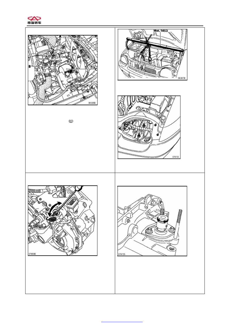
Supporting board for fasteners (A) 


Remove: 

– 

Mounting bracket for lifting ring (B) 

– 

Energy storage 


Remove  the  transmission  support  from  the  vehicle 

body. 


Lower  the  transmission  as  possible  as  you  can  and 

take off the control shaft cover. 

Rotate  the  control  shaft  a  quarter  turns  by  using  a 

screwdriver so as to loosen it. 


Remove the hydraulic unit 

Remount it 

Check whether positions of the two half-moon parts 

are correct. 

Smear  MOLYKOTE  33  (moderate)  onto  the  two 

half-moon parts. 


Place  the  control  shaft  onto  the  drive  mechanism 

module and lock it. 

Screwdriver  impression  and  shaft  pin  should  be 

aligned respectively with the marks. 

Put the flat washer in place. 

Remount the hydraulic unit onto the transmission. 

PDF created with pdfFactory Pro trial version 

www.pdffactory.com


CHERY SQR7080 EZ Drive SERVICE MANUAL


Put two  half-moon  parts and circlip into the  control 

shaft groove. 


Fix  the  hydraulic  unit  onto  the  transmission  by 

screwing its fixing bolts. 

Hold  the  control  shaft  with  a  screwdriver  so  as  to 

lock the drive module. 


Connect: 

–  The bus bar to the drive mechanism 
–  Fasteners 

Remount: 

–  Control shaft cover (smear grease onto the 

washer) 

–  The  transmission  support  onto  the  vehicle 

body 

Remove  the  engine  support  MOT.1453's  handheld 

tool. 

It  is  easy  to  carry  out  the  following  assembly 

procedure,  which  is  opposite  to  the  disassembly 

procedure. 

Fill  the  ELF  RENAULT  MATIC  D3  SYN 

DEXRON oil to the degree that the oil level is 32 to 

38 mm higher than the lowest mark line.   

Perform  the  corresponding  test  by  using  a  special 

tool.  (Refer  to  the  page  21-36  of  section  “special 

requirements  on  change  of  system  parts  and 

components of KIT electrically controlled hydraulic 

system”) 

Oil filling into oil tank 

The  mark  shown  on  the  oil  tank  is  the  lowest 

standard. 

Carry  out  the  energy  storage  removal  procedure. 

Make  sure  that  the  oil  level  is  32  to  38  mm  higher 

than the lowest mark line. 

Important tip: 

The oil level will be at the position indicated by the 

mark  line  (MIN)  when  the  energy  storage  has  been 

fully inflated (15 seconds after ignition). 


PDF created with pdfFactory Pro trial version 

www.pdffactory.com


CHERY SQR7080 EZ Drive SERVICE MANUAL


MECHANICAL TRANSMISSION – ELECTROMAGNETIC VALVE 

Tightening torque (unit: DAN.M) 


Energy storage 

High-pressure pipeline coupler 

1.4 

Lifting ring fixing nut 

2.1 

Electromagnetic valve bolt 

0.4 


Remarks: 

Before  maintaining  the  entire  automated 

mechanical transmission, use a special repair 

tool  to  remove  the  energy  storage  (refer  to 

the section of "ENERGY STORAGE"). 

Please refer to the related information in 21- 4. 

Disconnect: 

–  Battery 
–  Hydraulic 

unit 

wire 

harness 

connectors 

Remove: 

–  Air casing 
–  Air casing support 
–  Computer 
–  Transmission housing support 
–  Energy storage   
–  Hydraulic unit wire harness connector 

support (A) 


Remove: 

–  Lifting ring (B) mounting support 
–  Energy storage   

Disconnect  the  related  connections  for  electromagnetic 

valves. 

Remove  related  electromagnetic  valves  according  to  the 

following removal sequence. 


A: Electromagnetic valve (for the clutch) 

B: Electromagnetic valve 4 (for gear position selection) 

C: Electromagnetic valve 3 (for gear position selection) 

D: Electromagnetic valve 1 (for gear engagement) 

Remounting: 

Carry  out  the  remounting  procedure  that  is  opposite  to 

the removal procedure. 

Fill the ELF RENAULT MATIC D3 SYN DEXRON oil 

to the degree that the oil level is 32 to 38 mm higher than 

the lowest mark line.   

Perform  the  corresponding  test  by  using  a  special  tool. 

(Refer to the page 21-36 of section “special requirements 

on  change  of  system  parts  and  components  of  KIT 

electrically controlled hydraulic system”) 

Oil filling into oil tank 

The mark shown on the oil tank is the lowest standard. 

Carry  out  the  energy  storage  removal  procedure.  Make 

sure  that  the  oil  level  is  32  to  38  mm  higher  than  the 

lowest mark line. 

Important tip: 

The oil level will be at the position indicated by the mark 

line  (MIN)  when  the  energy  storage  has  been  fully 

inflated (15 seconds after ignition). 

PDF created with pdfFactory Pro trial version 

www.pdffactory.com


CHERY SQR7080 EZ Drive SERVICE MANUAL


Electromagnetic valve 2: 

Removal: 

It  is  necessary  to  lower  the  transmission  to  remove 

the clutch electromagnetic valve 2. 

Remove: 

–  Battery 
–  Air casing 
–  Electronic injection computer 
–  Left headlight 
–  Wheels 
–  Lamp  used  to  indicate  that  left  wheel  is 

stuck in mud 

–  Transmission weight 

Mount the engine support MOT 1453. 


Remove  the  transmission  support  connections  on 

the vehicle body. 


Lower the transmission as possible as you can. 

Disconnect 

the 

related 

connections 

for 

electromagnetic valves. 

Remove the electromagnetic valve 2 (D). 


Remounting: 

Carry out the remounting procedure that is opposite 

to the removal procedure. 

Fill  the  ELF  RENAULT  MATIC  D3  SYN 

DEXRON oil to the degree that the oil level is 32 to 

38 mm higher than the lowest mark line.   

Perform  the  corresponding  test  by  using  a  special 

tool.  (Refer  to  the  page  21-36  of  section  “special 

requirements  on  change  of  system  parts  and 

components of KIT electrically controlled hydraulic 

system”) 

Oil filling into oil tank 

The  mark  shown  on  the  oil  tank  is  the  lowest 

standard. 

Carry  out  the  energy  storage  removal  procedure. 

Make  sure  that  the  oil  level  is  32  to  38  mm  higher 

than the lowest mark line. 

Important tip: 

The oil level will be at the position indicated by the 

mark  line  (MIN)  when  the  energy  storage  has  been 

fully inflated (15 seconds after ignition). 


PDF created with pdfFactory Pro trial version 

www.pdffactory.com


Content   ..  150  151  152  153   ..