Chery S11 / Chery QQ. Manual - part 153
 

  Index      Chery     Chery S11 / Chery QQ - service repair manual


Search            


Content   ..  151  152  153  154   ..


Chery S11 / Chery QQ. Manual - part 153


CHERY SQR7080 EZ Drive SERVICE MANUAL


MECHANICAL TRANSMISSION 

– ENGAGEMENT POSITION SENSOR 

Tightening torque (unit: DAN.M) 


Power on position sensor bolt   

0.4 

Drive mechanism module nut 

2.1 

Lifting ring fixing nut 

2.1 

High-pressure pipeline coupler 

1.4 

Energy storage 

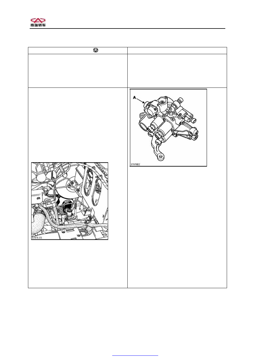
Disconnect the engagement position connector (A) 

Remove the engagement position sensor (A) 


Remarks: 

Before 

maintaining 

the 

entire 

automated 

mechanical transmission, use a special repair tool 

to remove the energy storage (refer to the section 

of "ENERGY STORAGE"). 

When  removing  the  engagement  position  sensor,  it 

is  unnecessary  to  remove  the  drive  mechanism 

module.   

Removal: 

Remove  the  potentiometer  for  accelerator  and 

footbrake and its support. 


Remounting: 

Carry out the remounting procedure that is opposite 

to the removal procedure. 

Perform  the  corresponding  test  by  using  a  special 

tool.  (Refer  to  the  page  21-36  of  section  “special 

requirements  on  change  of  system  parts  and 

components of KIT electrically controlled hydraulic 

system”) 

Oil filling into oil tank 

The  mark  shown  on  the  oil  tank  is  the  lowest 

standard. 

Carry  out  the  energy  storage  removal  procedure. 

Make  sure  that  the  oil  level  is  32  to  38  mm  higher 

than the lowest mark line. 

Important tip: 

The oil level will be at the position indicated by the 

mark  line  (MIN)  when  the  energy  storage  has  been 

fully inflated (15 seconds after ignition). 


PDF created with pdfFactory Pro trial version 

www.pdffactory.com


CHERY SQR7080 EZ Drive SERVICE MANUAL


MECHANICAL TRANSMISSION 

– GEAR POSITION SELECTION SENSOR 

Tightening torque (unit: DAN.M) 


Power on position sensor bolt   

0.4 

Electromagnetic valve 

0.4 

Lifting ring fixing nut 

2.1 

High-pressure pipeline coupler 

1.4 

Energy storage 

Disconnect the gear position selection connector (B) 

Remove the gear position selection sensor (B) 


Remarks: 

Before 

maintaining 

the 

entire 

automated 

mechanical transmission, use a special repair tool 

to remove the energy storage (refer to the section 

of "ENERGY STORAGE"). 

Before  removing  the  gear  position  selection  sensor, 

it is necessary to change to the 1st gear. 


Removal: 

Disconnect the battery. 

Remove: 

–  Air casing 
–  Air casing support 

Disconnect  the  hydraulic  unit  wire  harness 

connector (A). 

Remove  the  hydraulic  unit  wire  harness  connector 

support (A). 


Remounting: 

Check the capability of the selective sensor to rotate 

freely. 

Carry  out  the  following  remounting  procedure  that 

is opposite to the removal procedure. 

Perform  the  corresponding  test  by  using  a  special 

tool.  (Refer  to  the  page  21-36  of  section  “special 

requirements  on  change  of  system  parts  and 

components of KIT electrically controlled hydraulic 

system”) 

Oil filling into oil tank 

The  mark  shown  on  the  oil  tank  is  the  lowest 

standard. 

Carry  out  the  energy  storage  removal  procedure. 

Make  sure  that  the  oil  level  is  32  to  38  mm  higher 

than the lowest mark line. 

Important tip: 

The oil level will be at the position indicated by the 

mark  line  (MIN)  when  the  energy  storage  has  been 

fully inflated (15 seconds after ignition). 

PDF created with pdfFactory Pro trial version 

www.pdffactory.com


CHERY SQR7080 EZ Drive SERVICE MANUAL


MECHANICAL TRANSMISSION 

– CLUTCH POSITION SENSOR 

Tightening torque (unit: DAN.M) 


Clutch position sensor bolt   

0.4 

M8 bolt for electric pump set 

2.4 

M10 bolt for electric pump set 

4.4 

High-pressure pipeline coupler 

1.4 

Lifting ring fixing nut 

2.1 

Energy storage 

Remarks: 

Before 

maintaining 

the 

entire 

automated 

mechanical transmission, use a special repair tool 

to remove the energy storage (refer to the section 

of "ENERGY STORAGE"). 

Remove: 

–  Clutch actuator support 

Disconnect the clutch position sensor connector. 

Remove the clutch position sensor. (A) 


Remounting: 

Carry  out  the  following  remounting  procedure  that 

is opposite to the removal procedure. 

Perform  the  corresponding  test  by  using  a  special 

tool.  (Refer  to  the  page  21-36  of  section  "special 

requirements  on  change  of  system  parts  and 

components of KIT electrically controlled hydraulic 

system") 

Oil filling into oil tank 

The  mark  shown  on  the  oil  tank  is  the  lowest 

standard. 

Carry  out  the  energy  storage  removal  procedure. 

Make  sure  that  the  oil  level  is  32  to  38  mm  higher 

than the lowest mark line. 

Important tip: 

The oil level will be at the position indicated by the 

mark  line  (MIN)  when  the  energy  storage  has  been 

fully inflated (15 seconds after ignition). 


PDF created with pdfFactory Pro trial version 

www.pdffactory.com


CHERY SQR7080 EZ Drive SERVICE MANUAL


MECHANICAL TRANSMISSION – PRESSURE SENSOR 

Tightening torque (unit: DAN.M) 


Position sensor bolt   

0.4 

Drive mechanism module nut 

1.4 

Lifting ring fixing nut 

2.1 

High-pressure pipeline coupler              1.4 

Energy storage 

Remarks: 

Before 

maintaining 

the 

entire 

automated 

mechanical transmission, use a special repair tool 

to remove the energy storage (refer to the section 

of "ENERGY STORAGE"). 

Removal: 

Use an injector to evacuate the oil tank. 

Disconnect the pressure connector . 

Use  a  14  mm  precision  wrench  to  remove  the 

pressure sensor (C). 


Remounting: 

Carry  out  the  following  remounting  procedure  that 

is opposite to the removal procedure. 


Fill  the  ELF  RENAULT  MATIC  D3  SYN 

DEXRON oil to the degree that the oil level is 32 to 

38 mm higher than the lowest mark line.   


Perform  the  corresponding  test  by  using  a  special 

tool.  (Refer  to  the  page  21-36  of  section  “special 

requirements  on  change  of  system  parts  and 

components of KIT electrically controlled hydraulic 

system”) 

Oil filling into oil tank 

The  mark  shown  on  the  oil  tank  is  the  lowest 

standard. 

Carry  out  the  energy  storage  removal  procedure. 

Make  sure  that  the  oil  level  is  32  to  38  mm  higher 

than the lowest mark line. 

Important tip: 

The oil level will be at the position indicated by the 

mark  line  (MIN)  when  the  energy  storage  has  been 

fully inflated (15 seconds after ignition). 


PDF created with pdfFactory Pro trial version 

www.pdffactory.com


Content   ..  151  152  153  154   ..