Chery S11 / Chery QQ. Manual - part 10
 

  Index      Chery     Chery S11 / Chery QQ - service repair manual


Search            


Content   ..  8  9  10  11   ..


Chery S11 / Chery QQ. Manual - part 10


Chery QQ Service Manual                                            Transmission System


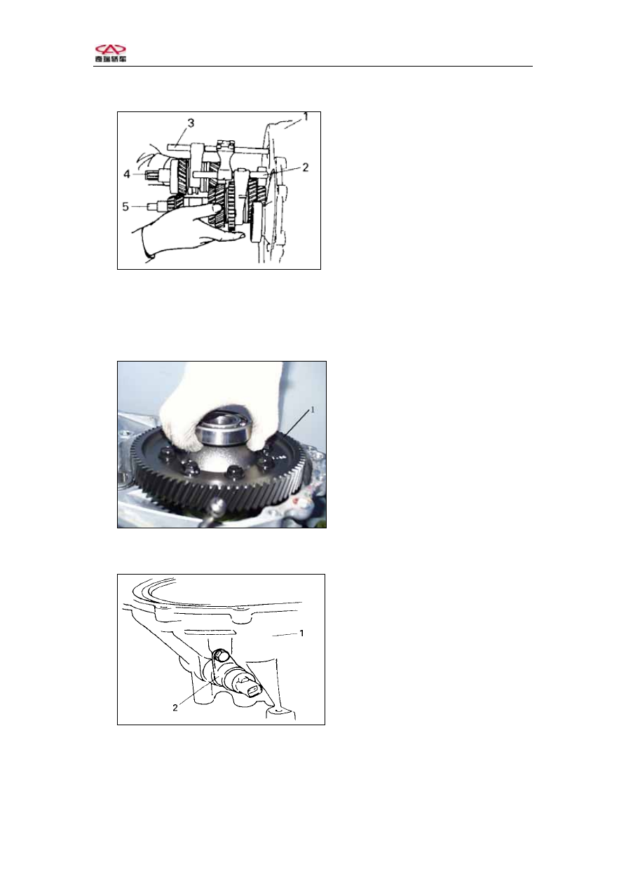
1- Clutch housing assembly     

2- 1st 2nd shift fork shaft assembly 

3- 3rd 4th shift fork shaft assembly 

4- Output shaft assembly   

5-Input shaft assembly 


            Fig.3-14 
 
3Clutch case assembly   

1.    Remove the differential assembly from the clutch case.   


1- Differential Assembly   

          Fig.3-15 
2. Loosen the bolt, pull out the speedometer driven gear assembly. 


1-  Clutch case   

2- Speedometer  driven

gear assembly 

                            Fig3-16 
Caution: Do not hurt speedometer case. 
3.Remove the input shaft oil seal .   

-61-  


4.Remove the output shaft bearing outer race. 


Chery QQ Service Manual                                            Transmission System


Notice: If the input shaft bearing still remains in the clutch case, use special tool to 
pull out the bearing.   


1- Input shaft oil seal   

2- Output shaft bearing

outer  

3- Special tool 


              Fig.3-17 
5. Loosen the bolt,    pull out the shift head. 


1- Shift head   

2- Shift lever   

3-Bolt  


Fig.3-18 

6. Loosen the shift lever bolt and gasket, take out the spring and ball. 
7. Remove the shift lever, boot and oil seal.     
8. Remove the differential oil seal from the clutch case.   

Notice: The used oil seal cannot be used repeatedly.   


1- Shift lever     

2- Boot   

3- Oil seal   

4- Blot   

5- Gasket   

6- Spring   

7-Ball  


Fig.3-19 


-62-  


Chery QQ Service Manual                                            Transmission System


4 Input shaft  assembly  

Disassemble: 


1. Use bearing puller to remove the input shaft right bearing.   


1- Special tool  

2- Input shaft   

3- 

Right bearing 


           Fig.3-20 
2. Use special tools to clip the 4th gear, pull it out with the 5th gear spacer, left 

bearing. 

Caution: Do not clip the gear head, or the 4th gear may be hurt.   


1- Special tool  

2- Input shaft   

3- 

Left bearing 


4-4th gear  


   Fig.3-21 

3.Take out the 4th gear Needle roller bearing and Synchronizer ring. 
4. Use special tool to remove the snap ring. 

-63-  


Chery QQ Service Manual                                            Transmission System


1- Snap ring   

2- Synchronizer ring   

3- Special tool  


           Fig.3-22 


5.Remove the synchronizer assembly and 3rd gear. 
6.Remove the 3rd gear needle roller bearing . 


1- Input shaft     

2- Synchronizer

 assembly 


3- Synchronizer

 ring 


4- 3rd gear   

          Fig.3-23 

7. Disassemble the Synchronizer assembly. 


Check and re-install: 

1.Clean up all the parts, check if there is anything abnormal. 
2.If Synchronizer components  need  repair ,  measure synchronizer ring 

clearance  “a”  to    gear, then decide whether change it. 


1- Gear   

2-Synchronizer ring 

          Fig.3-24 

-64-  


Content   ..  8  9  10  11   ..