Chery A18. Manual - part 44
 

  Index      Chery     Chery A18 - service repair manual


Search            


Content   ..  42  43  44  45   ..


Chery A18. Manual - part 44


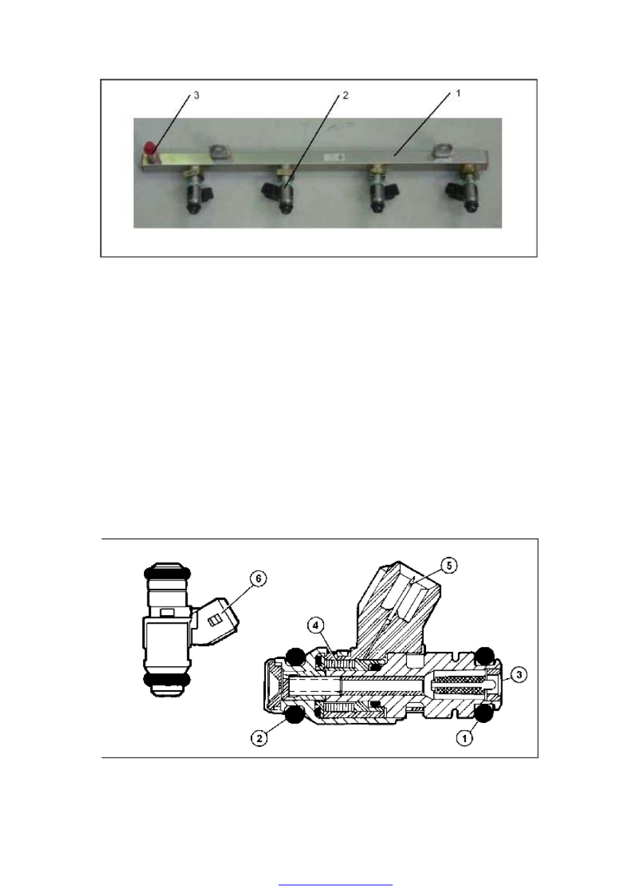
1.Fuel Rail                    2.Fuel Injector                  3.Fuel Feeding Port 


Fuel injector 

This system adopts head supplying single hole Fuel injector, and fuel injection pressure is 
3.5bar. Fuel injected from fuel injector keeps in atomization and comes into cone angle (15 
degree to injection nozzle axis). 

Control logic of Fuel injector is “phase, order” controlling. These four fuel injectors are 
controlled by air input order of four cylinders. Fuel injector is open on expansion stroke till 
intake stroke started. 

Fuel injector is fixed on fuel rail, and fuel rail can press injector on fixed seat of intake 
manifold. Two O-type pads (1) (2) are used in sealing. Fuel is entering from upper side of 
fuel injector. Fuel injector includes coil (4) and electric terminal (5) on electric plug (6).


1. O-ring                            2. O-ring                                  3. Fuel Feeding Port                                         
4. Coil                                5. Electric Terminal                  6. Electric Plug 


Specification: 

Voltage: 12V 

Resistance: 13.8 ~ 15.2Ω± 10%(  on 23°C) 

Remark: Force on fuel injector socket in assembly and disassembly must be less 

than 120N, or it will influence function.


Caution 

·use of a deformed injector retaining clip will cause the injector to not engage 

correctly. Always use a new clip when reattaching the injector, otherwise it may 
cause the injector to rotate.


LUBRICATION SYSTEM 

DESCRIPTION OF LUBRICATION SYSTEM …… … …… ……… … …… ………B-2 

OIL PAN …… … …… ……… … …… ……… … …… ……… … …… ……… … …B-3   

DISASSEMBLY/ASSEMBLY  ……  ………  … …………  ………  …  …………  …B-3 


OIL FILLING …… ……… … …………………………… … ………… ……… … …B-5 

OIL STRAINER ASSEMBLY …… ……… … ………… ……… … ………… ……… B-5   

DISASSEMBLY/ASSEMBLY  ……  ………  …  …………  ………  …  …………  …B-5


OIL  PUMP  AND  FRONT  OIL  SEAL  …………………  …  …………  ………  …B-6


DISASSEMBLY/ASSEMBLY  ……  ………  … …………  ………  …  …………  …B-6


OIL FILTER AND OIL PRESSURE SENSOR …… ……… … ………… ……… …B-10


DISASSEMBLY/ASSEMBLY …… ……… … ………… ……… … ………… …B-10


OIL PRESSURE TESTING PARAMETER LIST …… ……… … ………… ………B-11


ENGINE LUBRICATION SYSTEM 

DESCRIPTION OF LUBRICATION SYSTEM 

——The rotor oil pump (1) at the front end of the 

crankshaft    sucks oil out of the oil pan (3) by 
oil  strainer  (2)  and  pressurizes  oil,  and  then 
the  pressurized  oil  will  enter  the  full-flow  oil 
filter  through  the  auxiliary  oil  passage  (4)  at 
the  left  side  of  the  cylinder(view  from  the 
front). A relief valve (6) is set up inside the oil 
pump  to  control  the  pressure  at  the  main  oil 
passage. 

The 

relief 

valve 

opens 

at 

440kpa+20kpa,  and  the  filtered  oil  flow  from 
the  center  hole  in  oil  filter  through the  center 
hole  of  the  filter  terminal  to  the  engine  main 
oil passage. 


——The main oil passage lubricate the main 

bearing through holes on the cylinder block 
and lubricate the connecting-rod bearing 
through the oil passage inside the crank shaft.   


——On the side of the vent pipe of the 

connecting-rod bearing is a small oil hole 
from    where oil will eject to lubricate piston 
pin and cylinder. 


——Oil  pressure  sensor  (8)  is  close  to  oil  filter, 

connected  to  the  main  passage  through  an 
internal  oil  passage.  And  engine  oil  will  be 
provided upward to the third camshaft  journal 
from the upper oil passage. 


——Other camshaft journals get oil from the 

middle passage of the camshaft, whose ends 
are sealed with steel balls.


1. Oil Pump Rotor Assembly 

2. Oil Strainer 

3. Oil Pan 

4. Cylinder Auxiliary Oil Passage 

5. Cylinder Main Oil Passage


6. Oil Pump Relief Valve 

7. Oil Filter 

8. Oil Pressure Sensor 

9. Camshaft 

10. Hydraulic Jib 


Content   ..  42  43  44  45   ..