Chery A15. Manual - part 288


  Index      Chery     Chery A15 - service repair manual


Search            


Content   ..  286  287  288  289   ..


Chery A15. Manual - part 288


III. Unfixing the Backup Light Switch 


1. Unfixing 


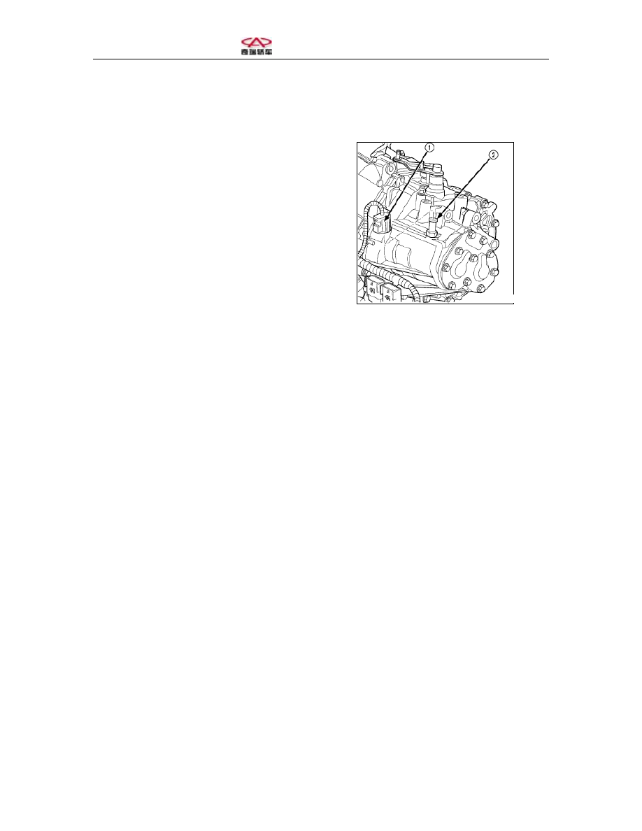
(1) Unfix the backup light switch plug 
on one side of the car (Figure 64).  


1-Plug 


2-Backup light switch 


Figure 64 Backup Light Switch 


(2) Screw off the switch from the 
gearbox 


2. Fixing 


(1) Fix the backup light switch. Reel 
some PTFE tape around the switch and 
screw the switch tight with a torque of 
24N.  


Note: do not excessively fasten the 
switch.  


(2) Connect the backup light switch tie-
in (Figure 64).  


(3) Check if the backup light is working 
properly.  


Section Five: Fixing and Unfixing of Differential 
 
I. Unfixing 
(1) Unfix the differential bearing cone 
(gear ring and differential) with the 
special tools (Figure 65 and 66).  


1-Speical tool 
2-Speical tool 
3-Differential assembly 
4-Speical tool 


1-Special tool 
2-Special tool adaptor 
3-Differential assembly 
4-Differential bearing cone 
5-Speical tool 


(2) Unscrew the bolts of the gear ring 
and the casing (Figure 67); use new bolts 
for assembly.  


Figure 6 Unfixing the Differential 
Bearing Cone 


Figure 66 Unfixing the Differential 
Bearing Cone 


1-Car speedometer drive gear 
2-Bearing 
3-Gear ring 
4-Gear ring bolts 


(3) Use an appropriate screw driver to 
pry out the car speedometer drive gear 
(Figure 68 and 69).  


1-Car speedometer drive gear 
2-Differential assembly 


1-Car speedometer drive gear 
2-Differential assembly 


(4) Dismantle the pinion thrust pin with 
a hammer or an appropriate punch 
(Figure 70 and 71). 


Figure 67 Unfixing the Gear Ring Bolts 
and Gear Ring 


Figure 68 Unfixing the Car Speedometer 
Drive Gear 


Figure 69 Taking off the Car 
Speedometer Drive Gear 


1-Gear ring 
2-Pinion shaft thrust pin 
3-Car speedometer drive gear 


1-Differential assembly 
2-Car speedometer drive gear 
3-Pinion shaft thrust pin 


(5) Unfix the pinion shaft (Figure 72). 


1-Differential assembly 
2-Pinion shaft 
3- Car speedometer drive gear 
4- Pinion shaft thrust pin 


(6) Unfix the pinion, side gear and thrust 
bearing (Figure 73 and 74). 


Figure 70 Unfixing the Pinion Shaft 
Thrust Pin 


Figure 71 Unfixing the Thrust Pin 


Figure 72 Unfixing the Pinion Shaft 


Content   ..  286  287  288  289   ..