Chery A15. Manual - part 287
 

  Index      Chery     Chery A15 - service repair manual


Search            


Content   ..  285  286  287  288   ..


Chery A15. Manual - part 287


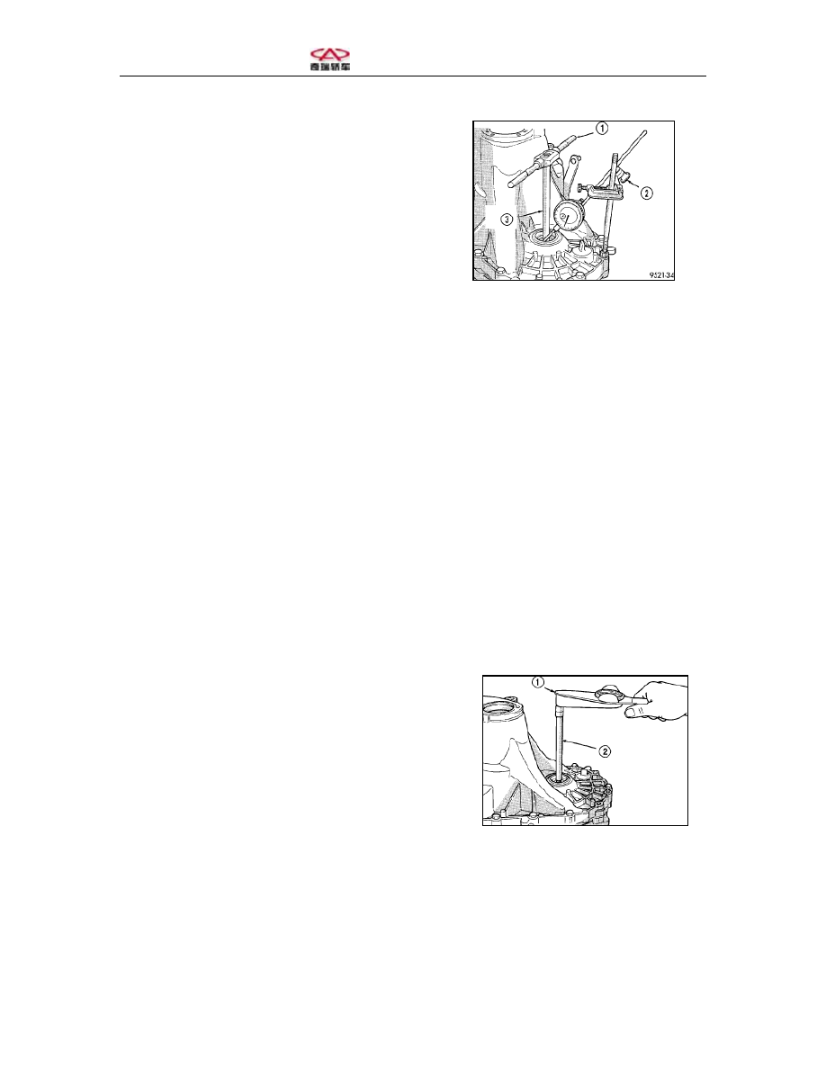
1-T handle 
2-Dial indicator 
3-Special tool 


Figure 60 Checking the End Clearance of Differential Bearing 
 
 
(7) Use gaskets to the extent that they 
can come into close contact with the 
bearing.  
(8) Screw off the bolts in the gearbox 
body. Dismantle the clutch cover and 
differential roller bearing outer ring. Fix 
the selected gaskets (Step 7) and then 
push the roller bearing outer ring into the 
clutch body.  
(9) Install the clutch outer casing and 
screw the set bolts with a torque of 
26N.m.  
(10) Check the torque on the differential 
assembly with the special tool and 
torque spanner (Figure 61) and torque 
shall be 6-12 in.lbs. Fix one gasket 
0.05mm (0.002 inch) in thickness if the 
torque is too big and an even thicker 
gasket if the torque is too small.  
 
1-Torque spanner 
2-Special tool 


(11) Check the torque. Repeat (Step 10) 
until an appropriate torque is obtained. 
Fix clutch body outer casing onto the 
gearbox and screw the bolts with a 
torque of 29N.m. 


Figure 61 Checking the Torque on 
Differential Bearing 


Section Three: Assembly of Gearbox 
 
I. Assembly 
(1) Fix the clutch assembly (if any) onto the input shaft and fix the gearbox in place.  
(2) Screw the set bolts of the gearbox and engine with a torque of 108N.m.  
(3) Jack up the engine and gearbox with a screw jack until the upper gasket bracket is 
aligned with the upper gasket. The screwing torque shall be 68N.m. 
(4) Remove the screw jack.  
(5) Fix the bolts of the clutch assembly and pressure plate (Figure 62). Array the drive 
disc and clutch assembly as per the markings made during disassembly. The screwing 
torque is 88N.m. 


Figure 62 Fixing/unfixing Gearbox 

1-Clutch pressure plate assembly 

3-Gearbox 

2-Retainer plate 


4-Clutch assembly bolt 

 
(6) Fix the starter and fasten the bolt with a torque of 54N.m. Make sure that the starter’s 
ground wire is well connected.  
(7) Connect the starter cable anode; the screwing torque of bolt is 10N.m 
(8) Fix the dust cover of the clutch body outer casing. 
(9) Fix the left engine and the gearbox crooked strut and steering mechanism.  
(10) Fix the power steering oil pipe.  
(11) Fix the right crooked strut; the screwing torque is 81N.m 
(12) Fix the two drive shafts of the front axle.  
(13) Add an appropriate amount of gearbox oil.  
(14) Noise will be heard when the hydraulic pipeline between the clutch main cylinder 
and driven cylinder is being connected. Check if the fast tie-ins are well connected.  
(15) Lower the car. 
(16) Connect the car speed sensor tie-in. 

 
(17) Connect the gearbox shifting fork and gear-shifting cable. Fix the upper retaining 
clip of the cable bracket.  
(18) Connect the backup light switch tie-in.  
(19) Install the battery into the retainer ring. 
(20) Fasten the screws of the storage battery’s position block.  
(21) Fix the air filter assembly.  
(22) Connect the storage battery cable.  
(23) Trial run the car to check if there is any leakage.  


II. Screwing Torque Specifications 
Do not reuse bolts that either have been applied with sealant or have torque lockup plate. 
Use new bolts.  
Torque specifications 

Backup light switch 

24-18N·m 

Reverse gear cable adjusting screw 

8-7 N·m 

Oil filler plug 

30-26N·m 

Differential gear ring bolt 

81-60N·m 

Gearbox dust cover 

12-10N·m 

Side plate cover bolt 

29-21N·m 

Bracket of front engine and gearbox 

108-80N·m 

Bolt of front bracket 

61-45N·m 

Bolt for the front bracket and the 
engine 

54-40N·m 

Horizontal crooked bracket to the 
engine 

54-40N·m 

Horizontal crooked bracket to the 
gearbox 

54–40N·m 

Bolt of the left bracket 

108-80N·m 

From left bracket to the gearbox 

54-40N·m 

Output shaft bearing belt 

11-9N·m 

Reverse gear shifting fork bracket 

11-9N·m 

Reverse idle wheel 

29–19N·m 

Gear-shifting cable bracket to the 
gearbox 

28-25N·m 

Gearbox casing bolt 

29-21N·m 

Gearbox to the engine 

95-70N·m 

Car speed sensor 

7-6N·m 


Section Four: Fixing and Unfixing of Gearbox Axle Shaft Oil Seal 
 
 
I. Unfixing 
(1) Dismantle the axle, differential and 
power transmission system in the proper 
sequence.  
(2) Insert one screw driver into the outer 
flange of the axle shaft oil seal (Figure 
63). 
(3) Slightly strike the screw driver with a 
small hammer to strike out the oil seal.  


1-Gearbox oil seal 
2-Screw driver 


II. Fixing 
(1) Clean the overflowing sealant in the 
gearbox oil seal hole.  
(2) Place the axle shaft oil seal onto the 
gearbox oil seal hole.  
(3) Fix the gearbox oil seal into the oil 
seal hole with the tool.  
(4) Slightly strike the oil seal into the 
gearbox casing where required.  
(5) Fix the drive shaft, differential and 
power equipment in the proper 
procedure.   


Figure 63 Unfixing the Gearbox Oil Seal 


Content   ..  285  286  287  288   ..