Chery A15. Manual - part 151
 

  Index      Chery     Chery A15 - service repair manual


Search            


Content   ..  149  150  151  152   ..


Chery A15. Manual - part 151


  Chery A15 Maintenance Manual 


Turn light 

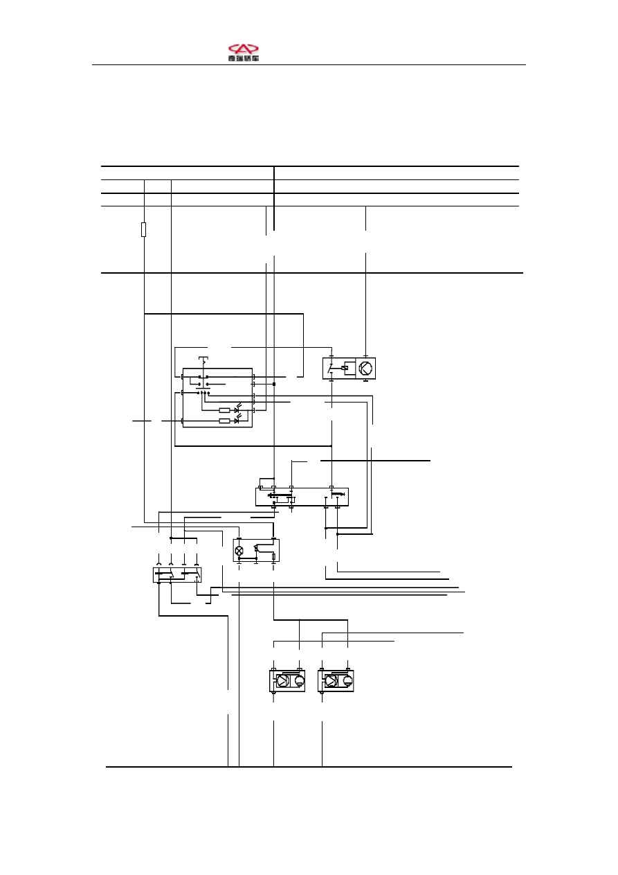
Turn light switch circuit, turn light and danger warning lamp lighting circuit are 
shown as follows: 

2/
87

7

1

6

4

3

5

8

棕0.5

3/
31

0.5

3

M

黄0.5

2

红/兰

0.5

1

0.5

3

M

黄0.5

红/兰0.5

2

1

红/兰0.5

5/G

红1.5 黄0.5

4/

56b

J2

红1.5

0.5

1.0

30

30

56

5

56b

R L

56a

K
6

6

1

3

7

8

2

5

4

至仪表22#

至仪表24#

、 、

至S31  S34  10A保险

至仪表25#远光指示灯

、 、

至S32  S33  10A

至S34 10A保险丝

至大灯开关

6#脚电源

至S31 10A保险丝

至大灯照

明开关


闪光继电器

30

15

X

31

至大灯
开关照

明1#

大灯调节电

( )

机  左 

大灯调节电

( )

机  右 

警告灯开关

黑/白

1.0

黑/绿1.0

白/黄1.5

0.5

白/黑

1.5

黑/白1.0

黑/绿

1.0

1.0

1.5

0.5

1.0

黑/兰1.5

白/绿1.5

变光
开关

黑/黄

1.5

大灯调
节开关

兰/白

0.5

黄/黑

白/黑

C308

4

6

白1.0

C314

FS
20

10A

D3


- 35 -    SAIC CHERY AUTOMOBILE CO., LTD 

  Chery A15 Maintenance Manual 


Analysis: when ignition switch is ON, current transfers from wire 15# via fuse FS20 
to terminal 3 of distress warning switch then via normally closed contact within 
distress warning switch to distress warning relay, which provides distress warning 
relay with a power source, so as to switch on and off the said relay contact with a 
certain frequency. When the said contact is switched on, current reaches turn light 
switch via the said contact, if steering switch is in the middle position, then no turn 
light works; if turn light switch is in the left position, current passes through the left 
switch position, and supplies power to turn lights on the front left, rear left and left 
side, while at the same time flashes with a certain frequency. Meanwhile, wire 15# 
current passes through left indicator in the instrument, and the said indicator flashes 
simultaneously. Likewise, when turn light switch is in the right position, the right 
indicators in front right, rear right, right side and instrument flash with a certain 
frequency simultaneously. 

Warning lamp circuit analysis: 
When sliding distress warning switch, and ignition switch being ON, current 

transfers from wire 15# via fuse FS20 to contact in distress warning switch and then 
reaches flasher relay, and provides the said relay with a power source, which enables 
the flasher relay contact to cut off and close up with a certain frequency. When relay 
contact closes up, current flows back to distress relay, and supplies turn lights of front 
right, rear right, right side, front left, rear left, left side with power, and several turn 
lights flash simultaneously, left and right indicators in the instrument also flash 
simultaneously. 

Brake light circuit analysis: 
Step on brake pedal, brake light switch is closed up, wire 30# power reaches 

brake light switch via fuse FS16 and then flows to the 2 brake light grounds to form 
return circuit with 2 brake lights lit up.   

Check on the abnormal operation of turn light: 

When ignition switch is ON, turn light switch is in the left position, check if there 

is power output from terminal L of the turn light switch, if there is, check if the circuit 
from turn light switch to left turn light is normal, if any abnormality is found, repair 
or replace it. In case of no power outputs, check if there is power in turn light switch 
terminal 5, if there is, replace steering switch, if there isn’t, check if flasher relay has 
power, if positive, repair circuit; if circuit is normal, replace flasher relay. If flasher 
relay has no power, check if there is power in distress warning switch terminals 1 and 
3, if terminal 3 has power, while terminal 1 has not, replace distress warning switch, if 
terminal 3 has no power, check fuse FS20 and power circuit.

- 35 -    CHERY AUTOMOBILE CO., LTD 

  Chery A15 Maintenance Manual 

Circuits of reversing light and fog light 

Circuits of reversing light and fog light are shown as the next page: 

Reversing light circuit analysis: 

When ignition switch is ON, current of wire 15# reaches reversing light switch 

via fuse FS24, when transmission lever is in the position of reverse, reversing switch 

closes up, current flows through left reversing light and right reversing light to light 

up them. 

Fog light circuit analysis: 

When headlight switch is in the position of Shift II or III, current reaches control 

coil of fog light relay via headlight switch, Shift II or III so as to enable fog light relay 

operation. Meanwhile, headlight II or III current forms return circuit via front fog 

light switch illuminating ground, to light up fog light switch lamp. When front fog 

light switch is closed up, current reaches fog light relay 

pull-in contact

 to front fog 

light switch via power wire 30#. The current is divided into two branches, one passing 

through fog light indicator ground within front fog light switch, the other return 

circuit passing through front left fog light, front right fog light ground and forming 

return circuit. In this case, indicators in the front fog light and front fog light switch 

are lit up simultaneously.   

When rear fog light switch is closed up, wire 30# reaches rear fog light switch via 

fuse FS14 and fog light relay 

pull-in contact 

and is divided into two return circuits 

with one passing through indicator ground in the rear fog light switch, the other 

passing through rear fog light ground and forming return circuit, and then indicators 

in rear fog light and rear fog light switch are lit up simultaneously. 


- 36 -    CHERY AUTOMOBILE CO., LTD 

  Chery A15 Maintenance Manual 


Reversing light, fog light 

Failure Description 

Failure Reason 

Troubleshooting Method 

High beam light or low 

beam light fails to light up 

1.Bulbs are all damaged 

2.Fuse blows 

3.Headlight switch failure 

4.Circuit failure 

1.Replace bulb 

2.Replace fuse 

3.Check, replace headlight 

switch 

4.Check circuit 

Only a headlight’s high 

beam light or low beam 

light fails to light up   

1.Bulb damaged 

2.Fuse blows 

3.Lamp holder or lead failure 

1.Replace bulb 

2.Replace fuse 

3.Check lamp holder or lead   

One side of high beam 

light or low beam light 

fails to light up   

1.Bulb damaged 

2.Fuse blows 

3.Headlight switch failure 

4.Lead or circuit ground failure 

1.Replace bulb 

2.Replace fuse 

3.Check headlight switch 

4.Check circuit 

Front headlights fail to 

light up 

1.Bulb damaged 

2.Fuse blows 

3.Headlight switch failure 

4.Lead or circuit ground failure 

1.Replace bulb 

2.Replace fuse 

3.Check headlight switch 

4.Check circuit 

- 37 -    CHERY AUTOMOBILE CO., LTD 


Content   ..  149  150  151  152   ..