Chery A series. Manual - part 57
 

  Index      Chery     Chery A series - service repair manual


Search            copyright infringement  


Content   ..  55  56  57  58   ..


Chery A series. Manual - part 57


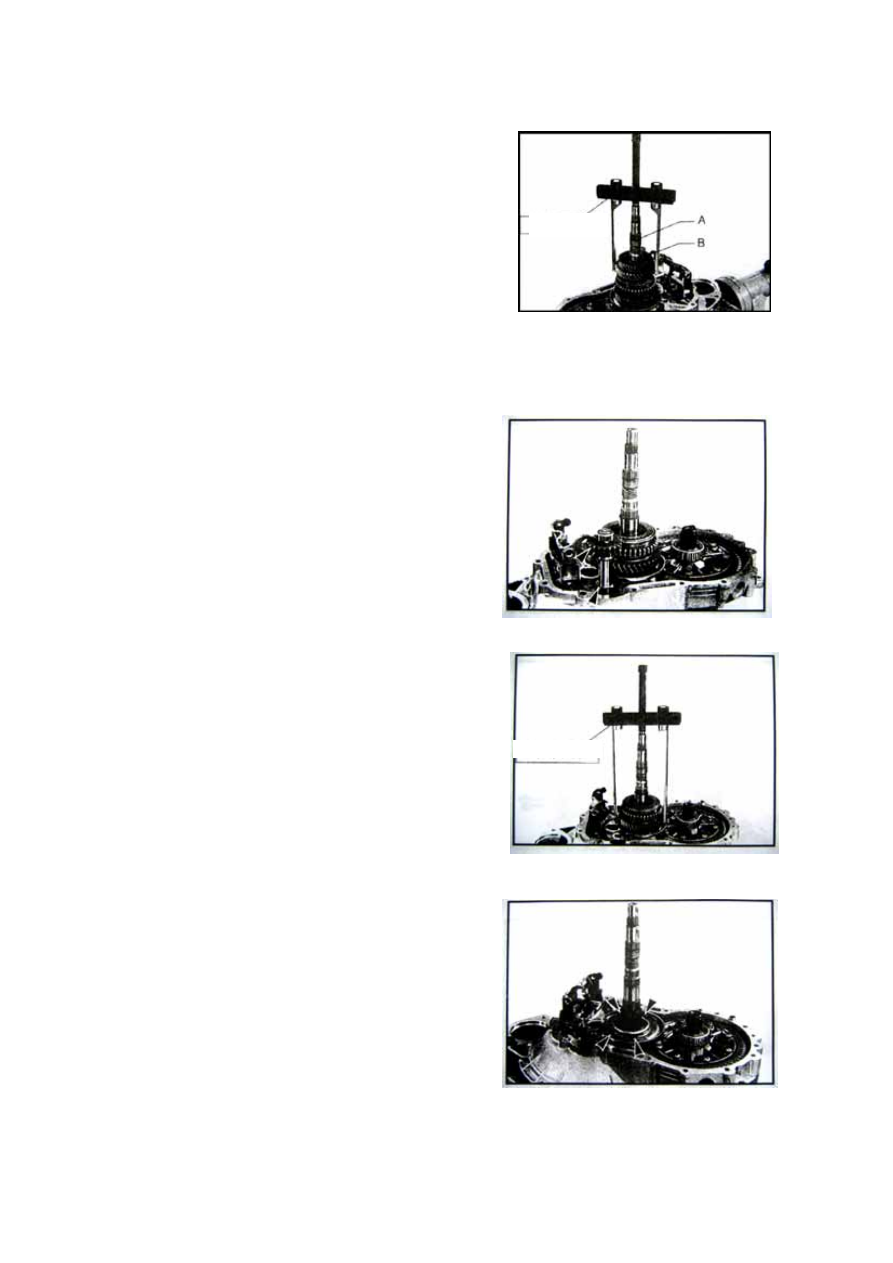
——Take off 3rd driven gear snap ring B from 

output shaft, and take off 3rd driven gear. And 
take off 2nd driven gear, needle bearing, and 
synchronizer ring from output shaft. (by 
special tool) 


Special Tool


——Prize up reverse shaft by reverse gear idler 

until both of them are off clutch housing. 


——Take off output shaft 1

st

 and 2

nd  

synchronizer 

assembly and 1

st

 synchronizer ring, 1

st

 driven 

gear and needle bearing, take off shift slice by 
a special tool. 


——Screw off output shaft front bearing plate 

fixing screw, take out output shaft front 
bearing plate and output shaft. 

——Take off differential assembly. 

——Disassemble reverse gear fork and bracket, 

returning spring and knob holder. 


Special Tool

J-20

Assembly: 

——The assembly of the transmission is in reverse 

of its disassembly, pay attention to the below 
items: 

1. Assemble differential assembly on clutch 

housing, at first do not assemble output flange. 

2. Assemble output shaft and output shaft front 

bearing plate, plug into fixing bolt and fasten 
by 40Nm moment. 

3. Assemble thrust shim needle bearing. Pay 

attention to the direction of the thrust shim, the 
inside diameter of thrust shim A should be 
integrate closely with the bearing holder. Pay 
attention that don’t mix up the 1st and 2nd 
synchronizer ring, 1st synchronizer ring is not 
sprayed molybdenum and has three gears 
missing. 


——The side with gears A towards 1st driven gear 

B when you assemble the 1st and 2nd 
synchronizer. 


——Assemble reverse gear idler and idler shaft 

onto clutch housing. 


J-21


——Assemble the needle bearing, synchronizer 

ring, and gear of 2nd and 3rd driven gear. 
When you assemble the 3rd driven gear, make 
sure that the side with bulge towards 2nd 
driven gear. 


——Use snap ring to adjust the axial size after the 

assembly of 3rd driven gear. Choose the 
thickest snap ring from the permitted size and 
assemble it into the snap ring groove. Make 
sure that the snap ring can not too big and can 
be assembled into the groove. 


Part No. 

thickness(mm) 

015-1700381AA 2.8 

015-170038AB 2.9 

015-1700381AC 3.0 

015-1700381AD 3.1 

015-1700381AE 3.2 


——Make sure put the balance spring of fork shaft 

into the clutch housing fork shaft hole. 


J-22


——Assemble the fork assembly into its right 

position, and then assemble the idler shaft. 

1—1st and 2nd fork 
2—3rd and 4th fork 
3—5th fork guide and bushing 

4—reverse gear fork guide 


——Assemble input shaft rear axle pump plate A, 

pay attention that the position of A should be 
the same as in the picture. Put new front and 
rear housing seal shim and assemble 
transmission housing.


——Put M17 bolt 1 into the threaded hole(see the 

picture), grasp the fork shaft and fillip the 
transmission housing with plastic hammer 
until the bearing out of position to the right 
place. Put in bolt 2 with 15Nm moment. Put in 
reverse gear shaft bolt and fasten by 20Nm 
moment, put in front/rear housing fixing bolt 
and fasten by 25Nm moment; fasten the rear 
bearing plate of input shaft by 15Nm moment.


J-23


Content   ..  55  56  57  58   ..