Chery A series. Manual - part 12
 

  Index      Chery     Chery A series - service repair manual


Search            copyright infringement  


Content   ..  10  11  12  13   ..


Chery A series. Manual - part 12


CAMSHAFT 

CAMSHAFT GEAR 

Removal 

Rotate the crankshaft to the compression TDC 
position of the first cylinder. 

Remove the belt. 

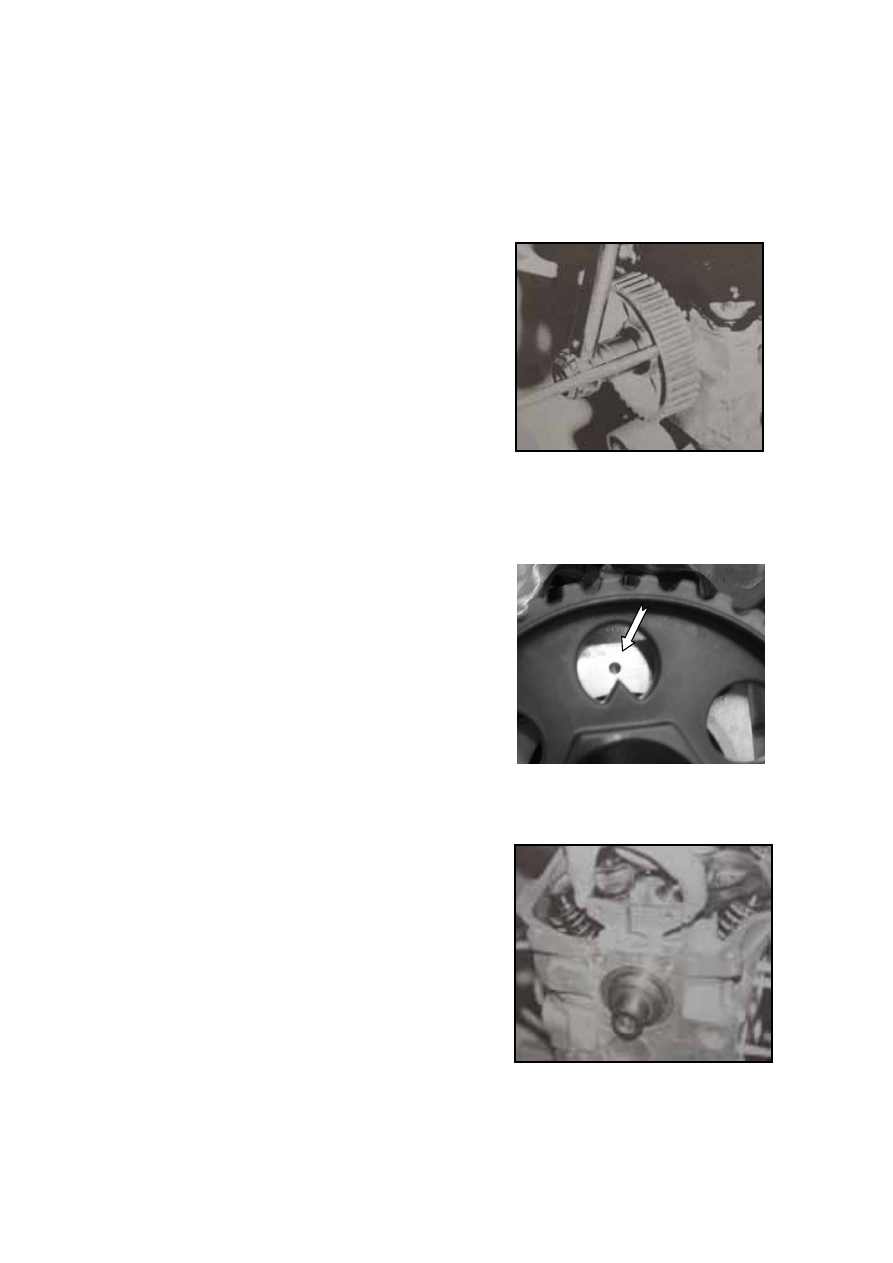
Put one pole into one hole of the cam shaft gear to 
lock it. Loosen the gear bolts and remove them and 
the gasket.   

Note:  

New bolts shall be used for reinstallation. The 
camshafts of different engines are not 
interchangeable. In case the cam shaft shall be 
replaced, replace it with a new one according to 
the indicators on the original gear.


Installation 

Check whether there are abrasion, pit corrosion or 
scrapes on the gear.   

Install the whitney key of the cam shaft, with a 
protrusion height of 1.64-2.11mm. 

Install the camshaft gear onto the camshaft and put 
new bolts into the gasket. The new bolts that 
haven’t been applied with a coat of glue in 
advance shall be applied with a coat of glue first 
and be tightened for a moment of 52-60N.m. 

Check whether the crank shaft is in the 
compression TDC position. 


CAMSHAFT AND CAMSHAFT THRUST 
SPACER 


Removal 

Measure the axial clearance of the cam shaft, 
which shall be between 0.049~0.129mm. 

Loosen the bolts of the thrust spacer to take them 
out.  

Take the thrust spacer out (as illustrated in the 
figure). 


B-25

Draw the cam shaft assembly out from the rear end
of the cylinder head and be careful not to damage
the cam shaft hole of the cylinder head during this
process. 


Inspection 

Check whether there is any abrasion on the cam 
and the journal of the cam shaft. Change the one 
with serious abrasion.   

Change the thrust space if the axial clearance of 
the cam shaft is above the specification.   

Measure the bore diameter of the cam shaft of the
cylinder head or check the relative displacement of
the journal and bore with the cam shaft. Change the
cam shaft if the bore is excessively wore. 


Cam Height 

Engine model 

Admission cam T (unit: mm) 

Exhaust cam T (unit: mm) 

480 38.602 

37.586 

480E 37.559 

37.559 


B-26

SIZE OF CAMSHAFT JOURNAL AND 
HOLE OF THE CYLINDER HEAD 

Installation 

To replace the cam shaft, observe the shape of the 
rear end of the cam shaft for right selection. 

Before installation, apply the cam of the cam shaft 
with hyperbolic gear oil or motor oil. The cam 
shaft shall be assembled from the cylinder head in 
a back-to-front order. 

Apply some motor oil to the thrust spacer of the 
cam shaft and put the thrust spacer into the groove 
of the cylinder head. 

Screw two bolts into the threaded holes of the 
thrust spacer and tighten them for a moment of 
9—13Nm. 

Check the axial clearance of the cam shaft, which 
shall be within the specified range. 

If adopting oversized hydraulic tappet (0.25), a 
carefully selected cam shaft shall be used, 
otherwise it will block the hydraulic tappet. 


1. Standard size 


Number of cam shaft 

journal 

Diameter of cam shaft journal 

(unit: mm) 

Diameter of the cam shaft hold of the 

cylinder head (unit: mm) 

1 44.74—44.76  44.783—44.808 

2 44.99—45.01  45.033—45.058 

3 45.24—45.26  45.283—45.308 

4 45.49—45.51  45.533—45.558 

5 45.74—45.76  45.783—45.808 


2. Oversized (0.38)     


Number of cam shaft 

journal 

Diameter of cam shaft journal 

(unit: mm) 

Diameter of the cam shaft hold of the 

cylinder head (unit: mm) 

1 45.12—45.14  45.163—45.188 

2 45.37—45.39  45.413—45.438 

3 45.62—45.64  45.663—45.688 

4 45.87—45.89  45.913—45.938 

5 46.12—46.14  45.163—45.188 


B-27


CRANKSHAFT 

CRANKSHAFT, CRANKSHAFT THRUST 
SPACER, BEARING SHELL AND MAIN 
BEARING CAP 

Removal 

Check the axial clearance of the crank shaft before 
removal.  

Kiss the end side of the crank shaft with the 
contacts of a dial gauge (less degree of shrinkage). 
Push the crank shaft away from the contacts and 
adjust the dial gauge to 0, then push the crank shaft 
to the direction of contacts as possible with a0 stout 
carrying pole. Check the reading of the dial gauge, 
which shall be the axial clearance. The axial 
clearance of a crank shaft is 0.092-0.303mm.   

The leaf of a clearance gauge can be used to check 
the axial clearance of a crank shaft if there is no 
dial gauge, which shall be placed between the third 
main bearing cap and crank shaft (push and pull the 
crank shaft). 

Loosen the bolts and studs of the main bearing 
shell, (beginning from the middle bearing cap), 
take out the bolts and the threaded rods to remove 
the main bearing cap and the lower shell of the 
main bearing shell. This lower shell shall still 
remain in the main bearing cap. 

Take the crank shaft out. 

Remove the crank shaft thrust spaces (2 pieces) 
from the cylinder block. 


Inspection 

Check the main journal and main bearing shell 
clearance. 

Clean the main journal of the crank shaft, the 
internal bore of the main bearing cap and main 
bearing shell with a non-woven fabrics. Place the 
plastic clearance gauge (its length slightly shorter 
than the length of the main journal) on the main 
journal, which shall be in parallel with the 
generator of the main journal. 

Note: Do not rotate the crank shaft! 


B-28


Content   ..  10  11  12  13   ..