Chery A series. Manual - part 13
 

  Index      Chery     Chery A series - service repair manual


Search            copyright infringement  


Content   ..  11  12  13  14   ..


Chery A series. Manual - part 13


Install the main bearing cap. Tighten the bolts of 
the main bearing cap at the moment of 90-100N.m 
by hands. Do not rotate the crank shaft. 


Remove  the main bearing bolts. Carefully take 
out the main bearing cap and arrange them in order. 
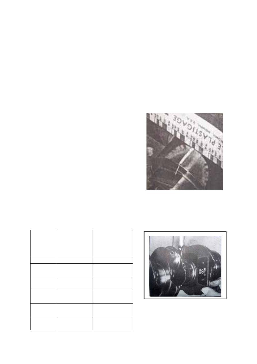
Read the bearing clearance according to the ratio 
on the envelope of the plastic clearance gauge. 
Check the bearing clearance from the third main 
bearing and extend to both sides. The main bearing 
clearance shall be 0.011—0.058mm.  

Check the bearing clearance of the connecting rod.

Check the bearing clearance of the connecting rod 
according to the above methods. The bearing 
clearance of the connecting rod shall be 0.006—
0.06mm. 


Size of connecting rod journal and connecting-rod bearing shell                                                             


Class 

Diameter of 

connecting rod 

journal 

(unit: mm) 

Thickness of 

connecting-rod 

bearing shell 

(unit: mm) 

Standard 47.89—47.91  1.480—1.487 

Downsized 

by 0.025 

47.89—47.91 1.492—1.499 

Downsized 

by 0.25 

47.64—47.66 1.605—1.612 

Downsized 

by 0.5 

47.39—47.41 1.730—1.737 

Downsized 

by 0.75 

47.14—47.16 1.855—1.862 

Downsized 

by1.0 

47.89—46.91 1.980—1.987 


B-29

Diameter of main journal and size of main bearing shell 


Class 

Diameter of main 

journal (unit: mm)

Diameter of the main bearing 

bore of the cylinder block     

(unit: mm) 

Thickness of the main 

bearing shell     

(unit: mm) 

Standard 57.98—58.00  62.2935+0.0065 2.131—2.138 

Oversized by 0.4 

57.98—58.00 

62.6935+0.0065 2.331—2.338 

Downsized by 0.02 

57.98—58.00 

62.2935+0.0065 2.141—2.148 

Downsized by 0.25 

57.73—57.75 

62.2935+0.0065 2.256—2.263 

Downsized by 0.50 

57.48—57.50 

62.2935+0.0065 2.381—2.388 

Downsized by 0.75 

57.23—57.25 

62.2935+0.0065 2.506—2.513 

Downsized by 0.25 

and oversized by 

0.4 

57.73—57.75 62.6935+0.0065 2.456—2.463 

Downsized by 0.50 

and oversized by 

0.4 

57.48—57.50 62.6935+0.0065 2.518—2.558 

Downsized by 0.75 

and oversized by 

0.4 

57.23—57.25 62.6935+0.0065 2.706—2.713 


Size of crank shaft thrust, thrust spacer and cylinder block thrust 


Class 

Size of cylinder block thrust 

(unit: mm) 

Size of crank shaft thrust   

(unit: mm) 

Thickness of thrust 

spacer (unit: mm) 

Standard 24+0.03 28.825-28.875 

2.326+0.025 

Oversized 

by 0.38 

24+0.03 29.205-29.255 

2.516+0.025 


2 thrust spacers 


B-30

Installation 

Before installation, tap the threaded hole on 
the cylinder block with tapping drill, 
especially those of the cylinder head bolts and 
main bearing bolts.   

   Cylinder head bolt: M10X1.5~6H 

   Main bearing bolt: M12X1.75~6H 

Installation of the whiney key of the crank 
shaft: gently drive the whiney key into the key 
slot. The clearance between the whiney key 
and key slot is 0.00~0.051mm. Check the 
protrusion after the whiney key is installed, 
which shall be 1.392~1.739mm. 

There are two pieces of crank shaft thrust 
spacers, which are installed on the front and 
rear thrust surfaces. Before installation, apply 
some motor oil on the side of the thrust spacer 
with oil groove and make this side towards the 
cylinder block and the other side towards the 
crank shaft. 

Apply some motor oil on the main journal, 
connecting rod journal, thrust surface and 
bearing shell before the crank shaft is 
installed. 

The top of the main bearing cap is cast with 
numbers- 1, 2, 3, 4, 5 and one arrow. During 
the assembly, start the installation in a 
front-to-back order and enable the guide 
finger towards the front end surface of the 
cylinder block. The width of 1, 2, 4, 5 main 
bearing cap is same, but that of the third main 
bearing cap is larger than others. The location 
of the main bearing cap depends on the rabbet 
and the rabbet and the cylinder block is 
interference fit, with the interference to be 
0.025~0.145mm. After the assembly, the sides 
of the first and fifth main bearing cap shall be 
even with or lower than the back and front 
end surface of the cylinder block. 


Among the main bearing bolts, 9 are 
hexagonal-head flanged bolts and 1 is stud. 
For transverse engine, the stud shall be 
installed on the left threaded hole of the 
second main bearing cap (seeing from the 
front) for installing the support of the suction 
strainer. For a north-south engine, the stud 


B-31

shall be installed on the left threaded hole of 
the fourth main bearing cap (seeing from the 
front).   

Apply some motor oil on the head joint before 
installing the main bearing cap bolts.   

Tighten the main bearing cap bolts and stud 
by    hands, then tighten them to the moment 
of 90~100Nm. 


The twist moment of the crank shaft 
(assembly with piston connecting rod) is 
16Nm max. 


Oil baffle assembly 

Removal 

Take the oil baffle assembly out from the 
right side of the back of the cylinder block 
(seeing from the front) 

Installation 

Install the oil baffle assembly from the right 
side of the back of the cylinder block (see 
from the front). The tension spring of the oil 
baffle assembly shall be lower than the 
crankcase flange of the cylinder block. 


B-32


Content   ..  11  12  13  14   ..