Chery A series. Manual - part 11
 

  Index      Chery     Chery A series - service repair manual


Search            copyright infringement  


Content   ..  9  10  11  12   ..


Chery A series. Manual - part 11


FRONT OIL SEAL 

CRANKSHAFT PULLEY 

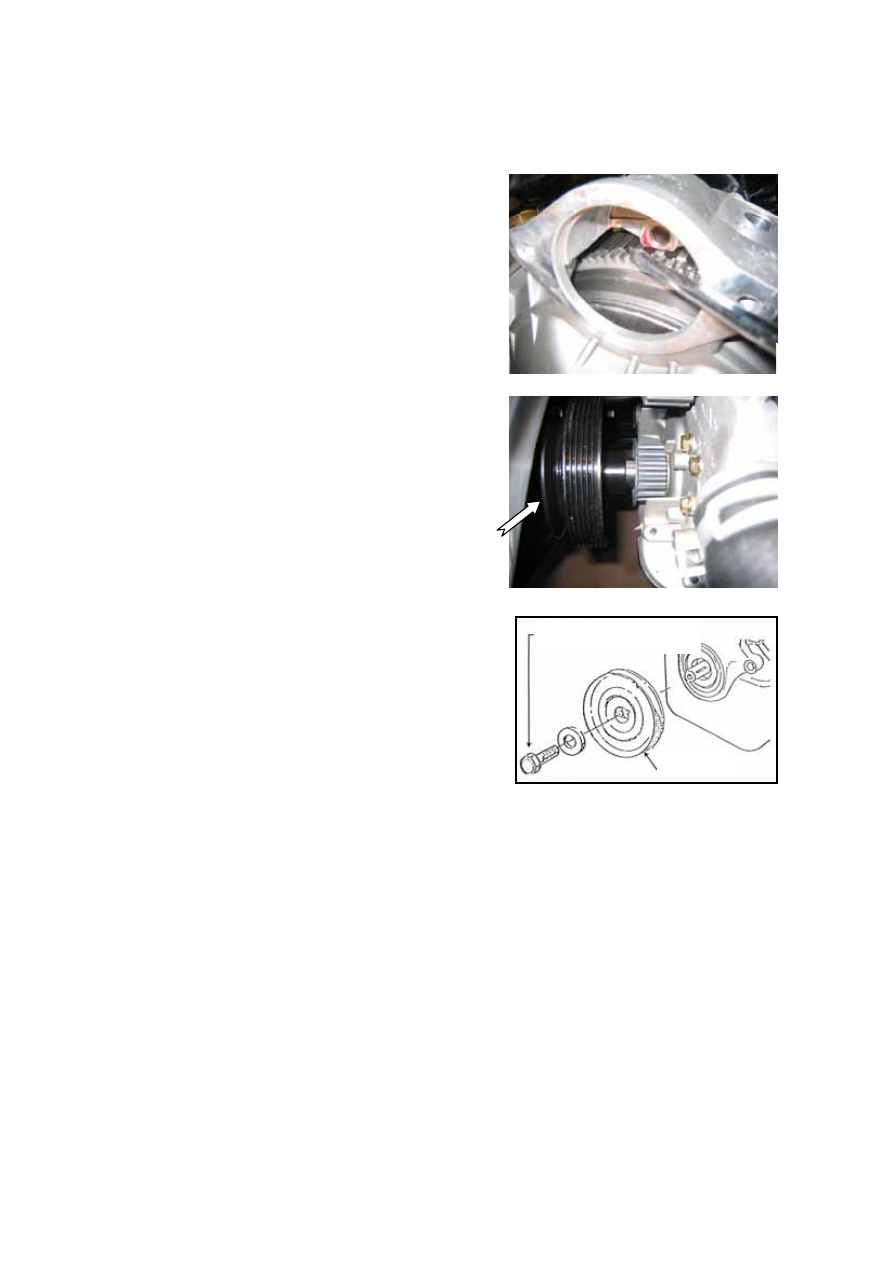
Removal  


Removal 3 fixing bolts on the starter to take it out. 
Fasten the flywheel ring gear with a proper 
screwdriver or rod to disenable the crank shaft to 
rotate. 


Loosen the fixing bolts of the crank pulley and 
take out the bolts and washer to pull out the pulley 
(use a gear puller, if necessary). 


Installation 

Clean the pulley and crankshaft journals and wipe 
clean the lube in the pulley groove. Install the 
pulley on the crank shaft journal, with the key slot 
to line up with the whiney key. 

Put the washer over the bolts and screw it in by 
hands. Fasten the flywheel ring gear to disenable 
the crank shaft to rotate. Tighten the bolts for a 
moment of 100-115N.m 


Pulley


Bolt: M12*35 
Tightening torque: 100~115Nm


B-21

CRANKSHAFT GEAR 


Removal 

Fix the crankshaft to disenable it to rotate and 
remove the pulley. 

Pull the crankshaft gear out by a wheel puller or 
two large-size screw drivers and remove the 
whiney key.   

Installation 

Check whether there are abrasion, pit corrosion or 
scrapes on the gear. 

Install the whiney key, with a protrusion height of 
1.392-1.739mm. 

Install the gasket and pay attention to its direction 
(with the warped surface forward). 

Install the crank shaft gear (with the convex 
surface forward), place it on the locating abutment 
with a auxiliary pulley and bolts. 


FRONT OIL SEAL REPLACEMENT   


Front Oil Seal Removal   

 
Cut the oil seal lip using a razor knife. 

Remove the oil seal using a screwdriver protected 

with a rag. 


Front Oil Seal Installation Note 

 
Apply clean engine oil to the oil seal lip. 

Push the oil seal slightly in by hand. 

Tap the oil seal in evenly using the SST and a 
hammer. 


FRONT 
OIL SEAL

B-22


REAR OIL SEAL 

FLY WHEEL REMOVAL AND 
INSTALLATION 


Removal 

Remove 9 fixing bolts. New bolts shall be used 
for installation. 

Remove the fly wheel to check whether there 
are cracks on the friction surface of the clutch 
plate and there is abrasion and pit corrosion on 
the teeth of the ring gear, etc.   


Installation 

The clearance of the ring gear and the fly 
wheel is 0.48-0.86mm. The ring gear shall be 
pressed into the fly wheel after heating. 

The gauge holes of the fly wheel and the 
locating journal are easy fit at a clearance of 
0.012-0.074mm. It


shall be gently pushed into 

the journal after alignment. Do not hammer at 
the crank shaft.   

During the assembly process, align the 
installation mark bore and the manufacturing 
bore on the crank shaft. Tighten 9 new bolts 
applied with a coat of glue in advance at a 
moment of 82-92Nm. 


REAR OIL SEAL REPLACEMENT 


Removal 

Remove 4 bolts (as indicated by arrows). 

Take the rear oil seal support assembly out. 

Take the rear oil seal support gasket. 


B-23


Pries the rear oil seal out of the rear oil seal 
support with a chisel or a screwdriver. Note: do 
not damage the rear oil seal support. 


Installation 

Put the support on the vice clamp whose jaw 
has a piece of wood.   

Make the side with the part numbers of the rear 
oil seal outward and align the rear oil seal with 
the rear oil seal support bore. Press the rear oil 
seal into its support with a vice clamp, with the 
clearance between the rear oil seal and oil seal 
support bore to be 0.26—0.50mm. 


Install the new rear oil seal support gasket. 

Install the rear oil seal assembly. Before 
assembling, wrap a piece of plastic plate on the 
crank shaft to avoid colliding the oil seal. And 
apply some motor oil on the oil seal edge and 
oil seal journal.   

Measure the out-of-flat of the bottom plane of 
the rear oil seal bracket and the sump flange 
surface of the cylinder block, which shall be 
within the range of  ±0.26mm. 


Tighten the 4 M6 bolts to a moment of 
8.0-11.0Nm. 

Take away the plastic tape. 


Bolt: M6*20(4 pcs) 
Tightening torque: 8~11Nm

Seal 
washer


B-24


Content   ..  9  10  11  12   ..