Chery A series. Manual - part 9
 

  Index      Chery     Chery A series - service repair manual


Search            copyright infringement  


Content   ..  7  8  9  10   ..


Chery A series. Manual - part 9


VALVE, VALVE SPRING AND OIL SEAL 
ASSEMBLY OF THE VALVE 


Removal 

 
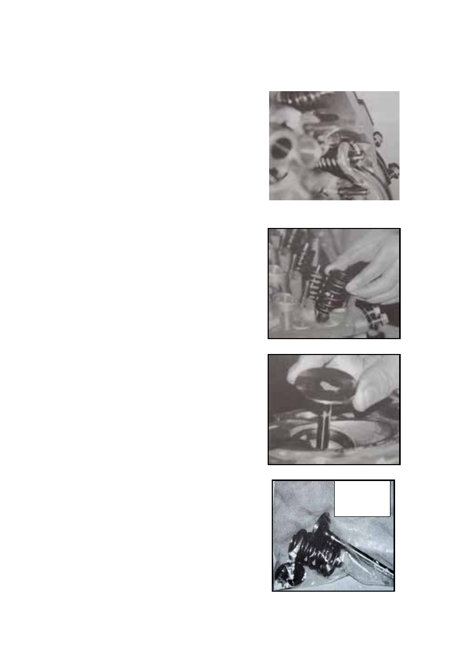
Compress the valve spring with a special 
compression device and take the valve cotter out. 
Do not over compress the spring, which shall be 
compressed to the travel stroke that the valve 
cotter can slide from the groove, otherwise the 
valve stem may bend.   

If the valve cotter cannot slide out when the spring 
is compressed, remove the compression device and 
place a proper pipe on the spring seat. In this way, 
the valve cotter will not be collided. Place a piece 
of wood on the valve head (with the side of the 
combustion chamber of the cylinder head towards 
the table) and then hammer at the top of the pipe. 


Reinstall the special compression device and 
compress the valve spring to take the cotter out. 
After the valve cotter is taken out, slowly loosen 
the bolts to remove the compression device. 

Remove the valve spring seat and valve spring and
take the valve oil seal and spring seat assembly out
with a screwdriver. The seal oil seal spring seat
must be replaced. 


Put one set of valve, valve cotter, spring and spring
seat into one plastic bag, each of which shall be
tagged with numbers for installing them back to the
original position. 


CYLINDER 

B-13


Valve stem size and fit clearance 


Intake(mm) Exhaust(mm) 

Class 

Diameter of 

valve stem 

Inner 

Diameter of 

valve guide 

Clearance

Diameter 

of valve 

stem 

Inner Diameter 

of valve guide 

Clearance

Standard  8.043


0

018

.

0

+

0

018

.

0

+

8.063—8.094

8.017

8.063—8.094 

Oversized 

0.4 

8.443


0

018

.

0

+

0

018

.

0

+

8.463—8.494

0.02— 

0.069 

8.417

8.463—8.494 

0.046— 

0.095 


Measure the free length and elasticity of the
valve spring 


Compression 

length (mm) 

Spring load 

(N) 

Free Length 

of Spring 

(mm) 

L

1

=37.084 422 

L

2

=27.7 892.7 

L

3

=27.0 945 

L

0

=47.2 


B-14

Grinding valve and valve seat ring 


UAES’s new 

two-valve   

Face angle of intake valve 

44º30′---45º30′

Width of the sealing band 

for the intake valve seat 

ring 

1.75---2.32mm 

Face angle of exhaust 

valve 

91º (0º-0º30ˊ) 

Width of the sealing band 

for the exhaust valve seat 

ring 

1.44±0.1 


Installation 
Before installation, the cylinder head shall be 
completely cleaned and there shall be no any trace 
of abrasive dust on the cylinder head, valve or 
valve guide.   

Lubricate the valve stem and valve guide bore with 
clean motor oil. 

Install the valve. The assembly shall be completed 
according to the original valve indicators. 

Note: The intake valves are interchangeable, but 

the exhaust valves are not. 


Press the valve oil seal and spring seat assembly
into the upper end of the valve guide, apply some
motor oil on the guide opening or the edge of the
valve oil seal and wrap the glove of the valve cotter
by adhesive tape. After the valve is installed, take
away the adhesive tape. 


Install the valve spring and valve spring seat, 
compress the valve spring seat to the stroke that 
enables the valve cotter groove to appear by special 
compression device and install the cotter. Then 
slowly release the compression device and remove 
it. 


After the whole valve cotter is installed, put the 
cylinder head on a piece of wood and knock at the 
small end of the valve stem by a plastic or copper 
hammer to help the valve mechanism to be in place 
better. 


B-15


Size of intake valve seat ring and cylinder head 

eat ring bore 

s 

Class 

Diameter of 

intake 

valve seat 

ring (unit: 

mm) 

Diameter of 

the seat ring 

bore of 

cylinder 

head (mm) 

Interfer

ence 

(mm) 

Standard 

43.877


01

.

0

01

.

0

+

43.763

025

.

0

0

+

Oversized 

0.5 

44.377


01

.

0

01

.

0

+

025

.

0

44.263

0

+

Oversized 

1.0 

44.877


01

.

0

01

.

0

+

025

.

0

44.763

0

+

0.079

— 

0.124 


Size of exhaust valve seat ring and cylinder head seat ring bore 

Class 

Diameter of exhaust valve 

seat ring (mm) 

Diameter of cylinder head 

seat ring bore (mm) 

Interference 

(mm) 

Standard 

38.877


01

.

0

01

.

0

+

38.263

0


025

.

0

+

 Oversized 

0.5 

39.377


01

.

0

01

.

0

+

38.763

0


025

.

0

+

Oversized 

1.0 

39.877


01

.

0

01

.

0

+

39.263

0


025

.

0

+

0.079—0.124 

UAES’s 

new 

two-valve  

38.377


01

.

0

01

.

0

+

38.263

0


025

.

0

+

Oversized 

0.5 

38.877


01

.

0

01

.

0

+

38.763

0


025

.

0

+

Oversized 

1.0 

39.377


01

.

0

01

.

0

+

39.263

0


025

.

0

+

0.079—0.124 


Size of valve guide and valve guide bore 

Class 

Valve guide bore 

(unit: mm) 

Diameter of cylinder head 

guide hole (unit: mm) 

Interference  

(unit: mm) 

Standard 

13.555


0

01

.

0

13.481—13.519 

Oversized 

14.305


0

01

.

0

14.231—14.269 

Oversized 

14.505


0

01

.

0

14.481—14.519 

0.026—0.07 


B-16


Content   ..  7  8  9  10   ..