Chery A series. Manual - part 8
 

  Index      Chery     Chery A series - service repair manual


Search            copyright infringement  


Content   ..  6  7  8  9   ..


Chery A series. Manual - part 8


VALVE CLEARANCE 

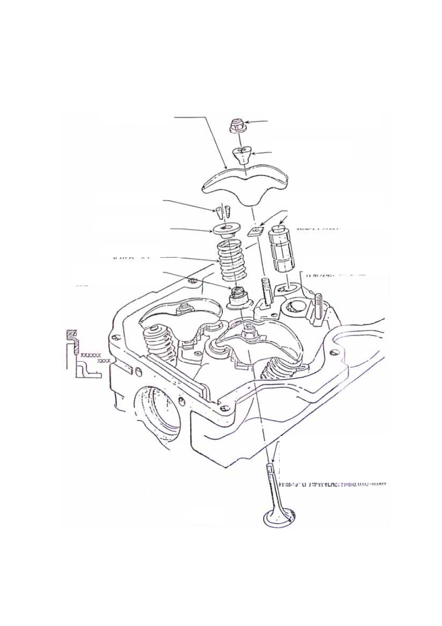
VALVE MECHANISM COMPONENTS 


Exhaust valve (4 pcs) (LH)
Clearance: 0.046~0.095 
 
Intake valve (4pcs) (RH) 
Clearance: 0.02~0.069


Lower seat of valve

spring (8 pcs) 

Rocker arm stud (8 pcs)
Torque: 18~23Nm


Valve spring (8 pcs) 

Upper seat of valve
spring (8 pcs) 

Hydraulic tappet (8 pcs)
Clearance: 0.023~0.065


Rocker ram seat washer (8 pcs)

Valve keeper (16 pcs) 

Rocker ram seat (8 pcs) 

Rocker nut (16 pcs) 
Tightening torque: 25~29Nm


Rocker arm (8 pcs) 


B-9

VALVE COVER AND GASKET 


Removal 


Remove 9 bolts to take out the cupped gasket
and high tension wire support, clutch and
throttle cable support. 


Remove the valve cover and gasket assembly. 

Take the sheet gasket out. 


Installation 
 

Clean the junction face of the cylinder head 
and the valve cover. 

Push the wedge of the sheet gasket for the 
valve cover into corresponding valve cover to 
integrate them. 

Install the combined valve cover and sheet 
gasket assembly on the cylinder head. 

Put 9 hexagonal-head long cylindrical end 
bolts into the cupped gaskets and supports and 
screw them into the cylinder head. 

Tighten the bolts in 2 steps according to the 
graphics and tightening order. First step: 
tighten them to the moment of 
4.0-6.0Nm.Second step: tighten them to the 
moment of 8.0-10.0Nm. 


C

u

p

p

ed

 g

as

k

et


G

as

k

et

 a

ss

em

b

ly

fo

r v

al

v

co

v

er


Cupped 
gasket 

Valve Cover

B-10

ROCKER MECHANISM 


Removal 

Loosen the rocker nuts to take them out. 


Take the level bracket out.   

Take the rocker arm out. 

Take the gasket of the level bracket out.   

Place each set of rock arm and level 
bracket in one same plastic bag for 
distinction. The removed rocker nuts 
cannot be reused. 


Installation: 

Check whether theire is abnormal abrasion on 
the contact surface of the rocker. Replace it if 
necessary.  

Put the rocker seat gasket into the stud.   

Lubricate the rocker arm and rocker seat by 
motor oil. 

Install the rocker arm and seat, screw in the 
new nuts by hands, then tighten them for the 
moment of 25—29N.m. 


Note: The corresponding hydraulic 

tappet shall be in the Min. 
position before each rocker 
arm is installed and tightened 
with nuts.


B-11

HYDRAULIC TAPPET 


Removal 

Take the hydraulic tappets out and place them 
into an oil-filled vessel to prevent the hydraulic 
tappet oil from leaking out.   

Check the top and bottom contact surfaces of 
the hydraulic tappet to observe whether there 
are abnormal abrasion or scrapes. If yes, 
replace it with new one if necessary. 


Installation 

Apply hyperbolic gear oil or motor oil on the 
tappet and external diameter as well as its two 
ends and place the tappet into the cylinder 
head hole in the original order. 


Size of Hydraulic Tappet 


Class 

Outside circle diameter 

(unit: mm) 

Hole diameter of the cylinder 

head tappet (unit: mm) 

Fit clearance 

 (unit: mm) 

Standard 

¢22.200~¢22.212 

¢22.25±0.015 

0.023~0.065 

T25 

¢22.454~¢22.466 

¢22.50±0.015 

0.023~0.065 

Tappet


B-12


Content   ..  6  7  8  9   ..