Chery A series. Manual - part 10
 

  Index      Chery     Chery A series - service repair manual


Search            copyright infringement  


Content   ..  8  9  10  11   ..


Chery A series. Manual - part 10


COMPRESSION PRESSURE 

COMPRESSION INSPECTION 

Warning 

·Hot engines and oil can cause severe burns. Be careful not to burn yourself during 

removal/installation of each component. 

1. Verify that the battery is fully charged. 

·Recharge it if necessary. 

2. Warm up the engine to the normal operating temperature. 

3. Stop the engine and allow it to cool off for about 10 min

4. Perform “Fuel Line Safety Procedures”. Leave the fuel pump relay removed. 


Warning 

·Fuel vapor is hazardous. It can very easily ignite, causing serious injury and damage. 

Always keep sparks and flames away from fuel. 

·Fuel line spills and leakage are dangerous.    Fuel can ignite and cause serious injuries 

or death and damage. Fuel can also irritate skin and eyes. To prevent this, always 
complete the “Fuel Line Safety Procedure”. 


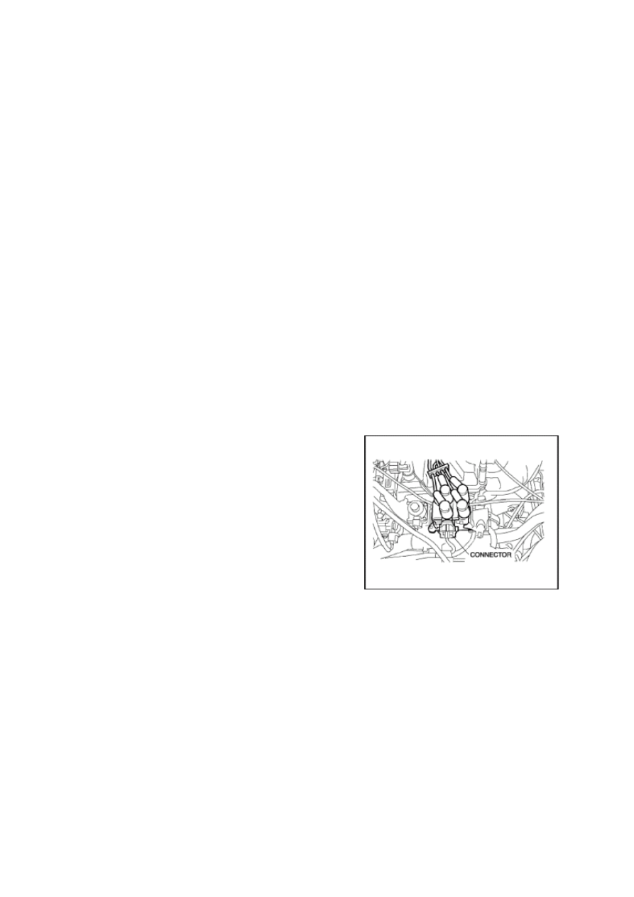
5. Remove the ignition coil connector. 

6. Remove the spark plugs. 

7. Connect a compression gauge into the spark plug 

hole. 

8. Fully depress the accelerator pedal and crank the 

engine. 

9. Note the maximum gauge reading. 

10. Inspect each cylinder as above. 


·If the measured value is less than the limited value,  or there is a cylinder whose 

compression value varies from that of other cylinders, add a small amount of engine oil 
through the spark plug hole. Then measure the compression pressure and perform the 
respective operations for the following cases. 

— If the compression increases, the piston, the piston rings, or cylinder wall may be worn 

and overhaul is required. 

— If the compression stays low, a valve may be stuck or improperly seated and overhaul is 

required. 

— If the compression in adjacent cylinders stays low, the cylinder head gasket may be 

damaged or the cylinder head distorted and overhaul is required. 

B-17


Cylinder Pressure Standard Value1.00-1.35 Mpa (10-13.5 kgf/cm2) 


11. Disconnect the compression gauge. 

12. Install the spark plugs.   

13. Connect the ignition coil connector. 

14. Install the fuel pump relay.   


B-18

CYLINDER HEAD GASKET


CYLINDER HEAD GASKET 
REPLACEMENT 


Removal 

Rotate the cam shaft clockwise until the key slot 
goes downwards vertically.   

Loosen the bolts on the cylinder head in the order 
illustrated in the figure.   


Note: The bolts removed from the cylinder head 

must be changed and cannot be reused. 


Inspection and Installation 

Check the out-of-flat of the base plane of the 
cylinder head, which shall not be above 0.15mm. 


Clean the threaded holes of the cylinder block. No 
lubricant shall be settled in the threaded holes, 
otherwise the liquid pressure may lead to the 
cracking of the cylinder block after the bolts are 
screwed in.   


Rotate the crank shaft clockwise to the position 
that enables the piston of the first cylinder to be 
about 20mm lower than the top plane of the 
cylinder block, thus to avoid the valve to collide 
with the top of the piston when installing the 
cylinder head assembly.


B-19

Put the cylinder gasket into the dowel.   


Note: The side with indicator of the cylinder 

gasket shall be upward.   


Install the cylinder head in place with the key slot 
of the cam shaft downward vertically.   


Note: The cylinder  gasket can only be used for 

one time, so the removed one shall be 
replaced with a new one when removing 
the cylinder head.


Put the bolts and the flat gasket of the cylinder 
head into the threaded hole to screw them in by 
hands. 


Tighten the bolts of the cylinder head in four steps 
according to the order illustrated in the figure: 


a.  First step: tighten it at the moment of 

20-40N. 

b.  Second step: tighten it at the moment of 

20-40N. 

c.  Third step: rotate 90 degrees. 

d.  Fourth step: rotate 90 degrees.   

e. 

Moment-angular tension indicating 
wrench can be used for degree rotation. 


A. Location Pin    B. Gasket 


B-20


Content   ..  8  9  10  11   ..