Acura RSX Honda Integra. Manual - part 448


  Index      Acura     Acura RSX Honda Integra - service repair manual 2002-2006 year


Search            


Content   ..  446  447  448  449   ..


Acura RSX Honda Integra. Manual - part 448


01

02

S6M6A22J34200041501FHAT00

01

02

S6M6A22J34200041001FEAT00

22-131

22-131

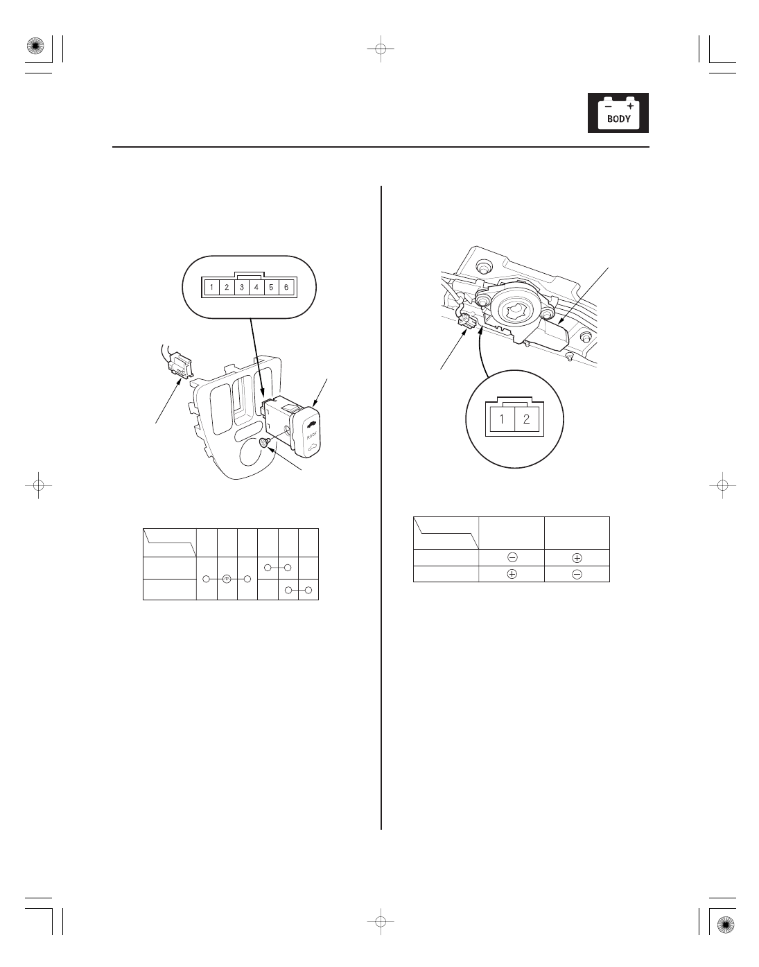
Switch Test/Replacement

Motor Test

B

C

A

B

A

Terminal

Position

CLOSE

OPEN

2

5

1

3

6

Terminal

Position

OPEN

CLOSE

1

2

1. Carefully pry out the driver’s switch panel

(see page 20-64).

2. Disconnect the 6P connector (A) from the moonroof

switch (B), then remove the switch.

3. Check for continuity between the terminals in each

switch position according to the table.

4. If the continuity is not as specified, replace the

illumination bulbs (C) or the switch.

1. Remove the headliner (see page 20-55).

2. Disconnect the 2P connector (A) from the moonroof

motor (B).

3. Check the motor by connecting power and ground

according to the table.

4. If the motor does not run, replace it.

NOTE: See closing force check (see page 20-48) for
motor clutch test.

05/06/27 18:04:43 61S6M040_220_0132

*01

S6M6A00J24200000000DAAT10

22-132

Horns

Component Location Index

UNDER-HOOD FUSE/RELAY BOX

HORN RELAY

HORN

CABLE REEL

HORN SWITCH

Test, page 22-62

Test, page 22-133
Replacement, page 22-133

Replacement, page 23-138

Test, page 22-134

05/06/27 18:04:44 61S6M040_220_0133

*01

S6M6A00J24200000000EAAT10

01

02

S6M6A00J24200032431FHAT20

22-133

22-133

Circuit Diagram

Horn Test/Replacement

BATTERY

UNDER-HOOD
FUSE/RELAY BOX

WHT/GRN

No. 7
(15 A)

ORN

BLU/RED

CABLE
REEL

HORN

HORN
SWITCH

: Grounds through steering column.

BRAKE LIGHTS

*

*

HORN
RELAY

A

B

B

A

1. Remove the front bumper.

• ’02-04 models (see page 20-90)
• ’05-06 models (see page 20-91)

2. Disconnect the 1P connector (A), and remove the

horn (B).

3. Test the horn by connecting battery power to the

terminal (A) and ground to the bracket (B). The horn
should sound.

4. If it fails to sound, replace it.

5. Install the horn in the reverse order of removal.

05/06/27 18:04:45 61S6M040_220_0134

*01

01

S6M6A00J24200032411FEAT10

22-134

Horns

Horn Switch Test

A

B

A

B

1. Remove the steering column covers (see page

17-25).

2. Disconnect the dashboard wire harness 5P

connector (A) from the cable reel (B).

3. Using a jumper wire, connect the dashboard wire

harness 5P connector No. 2 terminal to body
ground.

• If the horn sounds, go to step 4.
• If the horn does not sound, check these items:

– Horn relay
– No. 7 (15 A) fuse in the under-hood fuse/relay

box

– Horn (see page 22-133)
– An open in the wire

4. Check for continuity between the cable reel No. 2

terminal and body ground with the horn switch
pushed. There should be continuity. If there is no
continuity, go to step 5.

5. Reconnect the dashboard wire harness 5P

connector (A), and disconnect the horn switch
positive 1P connector (B).

6. Using a jumper wire, connect the horn switch

positive 1P connector to ground.

• If the horn sounds, go to step 7.
• If the horn does not sound, replace the cable reel.

7. Reconnect the horn switch positive 1P connector,

using a jumper wire, connect the steering wheel to
body ground.

8. Close the contact between the horn plate and the

contact place.

• If the horn sounds, replace the steering column.
• If the horn does not sound, replace the horn and

contact plate.

05/06/27 18:04:45 61S6M040_220_0135


Content   ..  446  447  448  449   ..