Acura RSX Honda Integra. Manual - part 348
 

  Index      Acura     Acura RSX Honda Integra - service repair manual 2002-2006 year


Search            


Content   ..  346  347  348  349   ..


Acura RSX Honda Integra. Manual - part 348


02

*02

04

01

18-25

108 N·m (11.0 kgf·m, 79.6 lbf·ft)

B
10 x 1.25 mm
55 N·m
(5.6 kgf·m, 41 lbf·ft)

A
8 x 1.25 mm
22 N·m
(2.2 kgf·m, 16 lbf·ft)

C

C
22 x 1.5 mm
181 N·m
(18.5 kgf·m,
134 lbf·ft)

A

B

B
8 x 1.25 mm

C

A
6 x 1.0 mm
9.8 N·m
(1.0 kgf·m, 7.2 lbf·ft)

1. Raise the rear of the vehicle, and support it with

safety stands in the proper locations (see page
1-12).

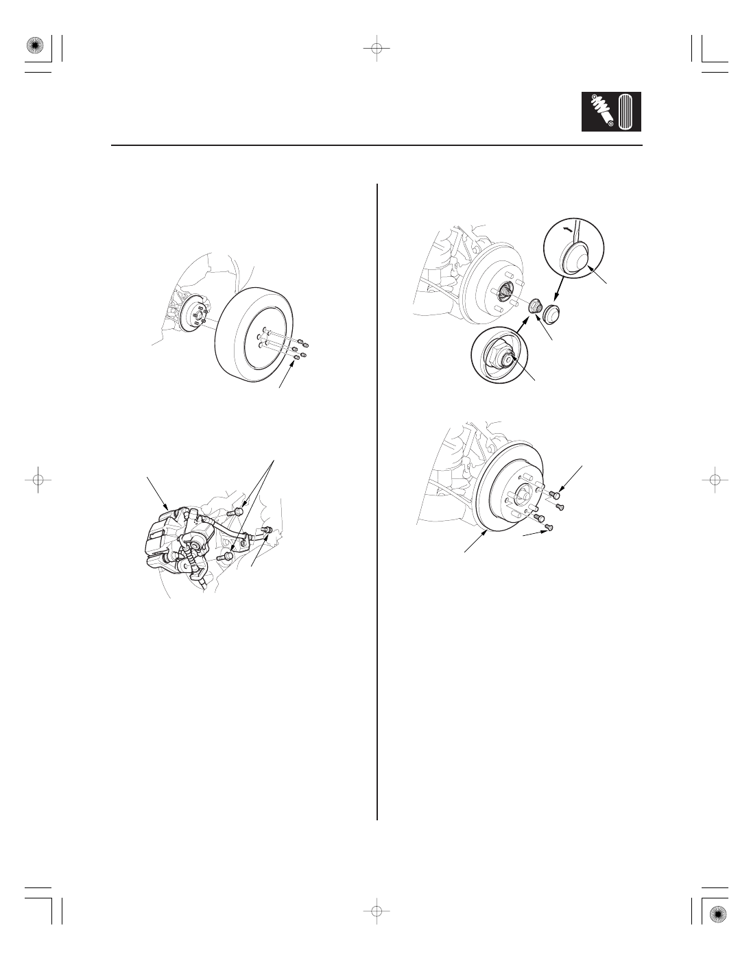
2. Remove the wheel cap, wheel nuts, and rear wheel.

3. Release the parking brake lever.

4. Remove the brake hose mounting bolt (A).

5. Remove the caliper bracket mounting bolts (B), and

hang the caliper (C) to one side. To prevent damage
to the caliper or brake hose, use a short piece of
wire to hang the caliper from the undercarriage.

6. Remove the hub cap (A), raise the stake (B), and

remove the spindle nut (C).

7. Remove the brake disc retaining screws (A).

8. Screw two 8 x 1.25 mm bolts (B) into the disc (C) to

push it away from the hub. Turn each bolt two turns
at a time to prevent cocking the disc excessively.
Remove the brake disc.

(cont’d)

05/06/27 18:17:41 61S6M040_180_0025

06

01

02

S6M6A00B44100036401KBAT00

18-26

18-26

Rear Suspension

Hub Bearing Unit Replacement
(cont’d)

Knuckle Replacement

A

A
6 x 1.0 mm
9.8 N·m
(1.0 kgf·m,
7.2 lbf·ft)

B

8 x 1.25 mm
22 N·m
(2.2 kgf·m, 16 lbf·ft)

6 x 1.0 mm
9.8 N·m
(1.0 kgf·m,
7.2 lbf·ft)

8 x 1.25 mm
22 N·m
(2.2 kgf·m,
16 lbf·ft)

B

A

C

9. Remove the hub bearing unit (A) from the spindle.

10. Install the hub bearing unit in the reverse order of

removal, and note these items:

• Tighten all mounting hardware to the specified

torque values.

• Use a new spindle nut on reassembly.
• Wash the spindle thoroughly in high flash point

solvent before reassembly.

• Before installing the spindle nut, apply a small

amount of engine oil to the seating surface of the
nut. After tightening, use a drift to stake the
spindle nut shoulder against the driveshaft.

• Before installing the brake disc, clean the mating

surface of the hub and the inside of the brake
disc.

• Use a new hub cap on reassembly.
• Before installing the wheel, clean the mating

surface of the brake disc and the inside of the
wheel.

1. Raise the rear of the vehicle, and support it with

safety stands in the proper locations (see page
1-12).

2. Remove the rear wheel.

3. Remove the brake disc and hub bearing unit

(see page 18-24).

4. Remove the flange bolts (A) and splash guard (B)

from the knuckle.

5. Remove the wheel sensor (A), brake hose

mounting bracket (B), and parking cable mounting
bracket (C) from the knuckle. Do not disconnect the
wheel sensor connector.

05/06/27 18:17:42 61S6M040_180_0026

03

02

18-27

B
12 x 1.25 mm
59 N·m
(6.0 kgf·m,
43 lbf·ft)

C

A

D
14 x 1.5 mm
93 N·m
(9.5 kgf·m, 69 lbf·ft)

C
12 x 1.25 mm
59 N·m
(6.0 kgf·m,
43 lbf·ft)

A

B

E

6. Place the floor jack under the trailing arm (A) to

support it.

Do not place the jack against the plate
section of the lower arm. Be careful not to
damage any suspension components.

7. Remove the flange bolt (B), then disconnect the

upper arm (C) from the knuckle.

8. Mark the cam positions of the adjusting bolt (A) and

adjusting cam (B), the remove the self-locking nut
(C), adjusting cam, and adjusting bolt. Discard the
self-locking nut.

9. Remove the flange bolt (D), and remove the

knuckle (E).

10. Install the knuckle in the reverse order of removal,

and note these items:

• First install all the suspension components, and

lightly tighten the bolts and nuts, then place a
floor jack under the lower arm, and raise the
suspension to load it with the vehicle’s weight
before fully tightening the bolts and nuts to the
specified torque values.

• Align the cam positions of the adjusting bolt and

adjusting cam with the marked positions when
tightening.

• Use a new self-locking nut on reassembly.
• Tighten all the mounting hardware to the

specified torque values.

• Use a new spindle nut on reassembly.
• Before installing the spindle nut, apply a small

amount of engine oil to the seating surface of the
nut. After tightening, use a drift to stake the
spindle nut shoulder against the driveshaft.

• Before installing the brake disc, clean the mating

surface of the hub and the inside of the brake
disc.

• Use a new hub cap on reassembly.
• Before installing the wheel, clean the mating

surface of the brake disc and the inside of the
wheel.

• Check the wheel alignment, and adjust it if

necessary (see page 18-4).

05/06/27 18:17:42 61S6M040_180_0027

01

02

03

S6M6A00B44100056851KBAT00

18-28

Rear Suspension

Stabilizer Bar Replacement

A
10 x 1.25 mm
38 N·m
(3.9 kgf·m, 28 lbf·ft)

E

D

C

B

A
8 x 1.25 mm
22 N·m
(2.2 kgf·m,
16 lbf·ft)

D

C

B

A

B

1. Raise the rear of the vehicle, and support it with

safety stands in the proper locations (see page
1-12).

2. Remove the rear wheel.

3. Remove the self-locking nuts (A) while holding the

joint pins (B) with a hex wrench (C), and disconnect
the stabilizer links (D) from the stabilizer bar (E) on
the right and left.

4. Remove the flange bolts (A) and bushing holders

(B), then remove the bushings (C) and the stabilizer
bar (D).

5. Install the stabilizer bar in the reverse order of

removal, and note these items:

• Use new self-locking nuts on reassembly.
• Make sure the right and left ends of the stabilizer

bar are installed on their respective sides of the
vehicle.

• Align the ends of the paint marks (A) on the

stabilizer bar with the bushings (B).

• Refer to Stabilizer Link Replacement (see page

18-29) to connect the stabilizer bar to the links.

05/06/27 18:17:43 61S6M040_180_0028


Content   ..  346  347  348  349   ..