Acura RSX Honda Integra. Manual - part 346


  Index      Acura     Acura RSX Honda Integra - service repair manual 2002-2006 year


Search            


Content   ..  344  345  346  347   ..


Acura RSX Honda Integra. Manual - part 346


01

*01

02

S6M6A00B20200056851KBAT00

18-17

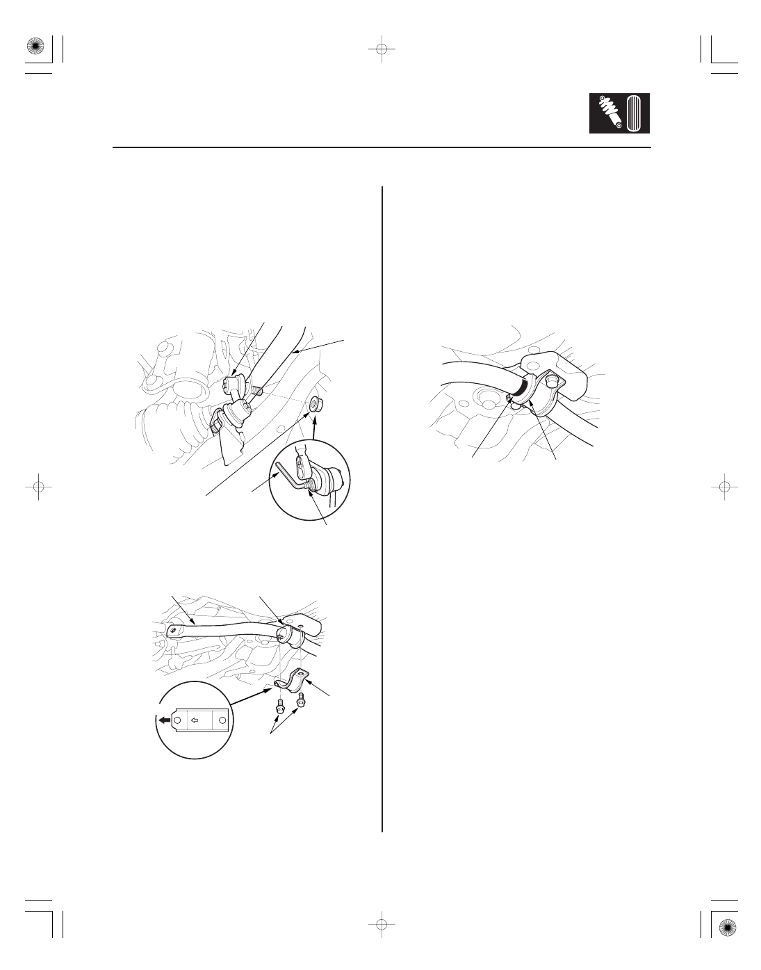
Stabilizer Bar Replacement

D

B

C

A
10 x 1.25 mm
38 N·m
(3.9 kgf·m,
28 lbf·ft)

E

A
10 x 1.25 mm
39 N·m
(4.0 kgf·m, 29 lbf·ft)

FRONT

D

C

B

A

B

1. Raise the front of the vehicle, and support it with

safety stands in the proper locations (see page
1-12).

2. Remove the front wheels.

3. Remove the self-locking nuts (A) while holding the

joint pin (B) with a hex wrench (C), and disconnect
the stabilizer links (D) from the stabilizer bar (E) on
the right and left.

4. Remove the flange bolts (A) and bushing holders

(B), then remove the bushings (C) and the stabilizer
bar (D).

5. Install the stabilizer bar in the reverse order of

removal, and note these items:

• Use new self-locking nuts on reassembly.
• Note the right and left direction of the stabilizer

bar.

• Align the ends of the paint marks (A) on the

stabilizer bar with each end of the bushings (B).

• Note the fore/aft direction of the bushing holders.
• Refer to Stabilizer Link Replacement to connect

the stabilizer bar to the links (see page 18-18).

05/06/27 18:17:17 61S6M040_180_0017

01

*01

01

S6M6A00B20200056861KDAT00

18-18

Front Suspension

Stabilizer Link Removal/Installation

E

B

D

C

A

D

C

A
10 x 1.25 mm
38 N·m
(3.9 kgf·m, 28 lbf·ft)

B
10 x 1.25 mm
39 N·m
(4.0 kgf·m, 29 lbf·ft)

C

D

A

B

E

1. Raise the front of the vehicle, and support it with

safety stands in the proper locations (see page
1-12).

2. Remove the front wheel.

3. Remove the self-locking nut (A) and flange nut (B)

while holding the respective joint pins (C) with a
hex wrench (D), then remove the stabilizer link (E).

4. Install the stabilizer link (A) on the stabilizer bar (B)

and lower arm (C) with the joint pins (D) set at the
center of their range of movement.

NOTE: The left stabilizer link has a yellow paint
mark (E), while the right stabilizer link has a white
paint mark.

5. Install the self-locking nut and flange nut, and

lightly tighten them.

NOTE: Use a new self-locking nut on reassembly.

6. Place the floor jack under the lower arm ball joint,

and raise the suspension to load it with the vehicle’s
weight.

Do not place the jack against the flat section
of the lower arm. Lifting the arm in this area
might bend it.

7. Tighten the new self-locking nut (A) and flange nut

(B) to the specified torque values while holding the
respective joint pins (C) with a hex wrench (D).

8. Reinstall all removed parts and test drive the

vehicle.

9. After 5 minutes of driving, tighten the self-locking

nut again to the specified torque values.

05/06/27 18:17:18 61S6M040_180_0018

01

*01

01

S6M6A00B20200037701KDAT00

Special Tools Required

18-19

Lower Arm Removal/Installation

D

E

B

C

A
10 x 1.25 mm
39 N·m
(4.0 kgf·m, 29 lbf·ft)

’02-04 models:

’05-06 models:

180 °

REAR

FRONT

OUTSIDE

90 °

A

B
12 x 1.25 mm
59

69 N·m

(6.0

7.0 kgf·m,

43

51 lbf·ft)

14 x 2.0 mm
88

98.1 N·m

(9.0

10.0 kgf·m,

65

72.3 lbf·ft)

OUTSIDE

REAR

FRONT

07MAC-SL0A202

12 x 1.25 mm:
07AAF-SDAA100
14 x 2.0 mm:
071AF-S3VA000

A
14 x 1.5 mm
98.1 N·m (10.0 kgf·m, 72.3 lbf·ft)

B

• Ball joint thread protector, 12 mm 07AAF-SDAA100
• Ball joint thread protector, 14 mm 071AF-S3VA000
• Ball joint remover, 28 mm 07MAC-SL0A202

1. Raise the front of the vehicle, and support it with

safety stands in the proper locations (see page
1-12).

2. Remove the front wheel.

3. Remove the flange nut (A) while holding the joint

pin (B) with a hex wrench (C), and disconnect the
stabilizer link (D) from the lower arm (E).

4. Remove the lock pin (A) from the lower arm ball

joint, and remove the castle nut (B).

NOTE: During installation, insert the new lock pin
as shown after tightening the nut.

5. Disconnect the lower arm from the knuckle using

the special tools (see page 18-10).

6. Remove the flange bolts (A), and remove the lower

arm (B).

7. Install the lower arm in the reverse order of

removal, and note these items:

• Be careful not to damage the ball joint boot when

connecting the lower arm to the knuckle.

• Before connecting the ball joint to the arm,

degrease the threaded section and tapered
portion of the ball joint pin, and the arm
connecting hole, and the threaded section and
mating surface of the castle nut.

• First install all the components and lightly tighten

the bolts and nuts, then raise the suspension to
load it with the vehicle’s weight before fully
tightening it to the specified torque values.

• Tighten all mounting hardware to the specified

torque values.

• Torque the castle nut to the lower torque

specification, then tighten it only far enough to
align the slot with the ball joint pin hole. Do not
align the castle nut by loosening it.

• Reinstall the lock pin on the castle nut after

torquing.

• Before installing the wheel, clean the mating

surface of the brake disc and the inside of the
wheel.

• Check the wheel alignment, and adjust it if

necessary (see page 18-4).

05/06/27 18:17:18 61S6M040_180_0019

*01

S6M6A00B20200019101KBAT00

Exploded View

18-20

Front Suspension

Damper/Spring Replacement

SELF-LOCKING NUT
12 x 1.25 mm
’02-04 models:
44 N·m (4.5 kgf·m, 33 lbf·ft)
’05-06 models:
59 N·m (6.0 kgf·m, 43 lbf·ft)

DAMPER MOUNTING BASE

DAMPER MOUNTING BEARING

UPPER SPRING SEAT

UPPER SPRING MOUNTING CUSHION

BUMP STOP

’05-06 models:

DAMPER UNIT

DAMPER SPRING

’05-06 models:

Replace.

Check for deformation.

Check for smooth operation.

Check for deterioration and damage.

Check for weakness
and damage.

Check for oil leaks,
gas leaks, and smooth operation.

Check for weakened compression and damage.

05/06/27 18:17:19 61S6M040_180_0020


Content   ..  344  345  346  347   ..