Acura RSX Honda Integra. Manual - part 300
*01
*02
*03
S6M6APPE10436436021FAAT10
−
−
−
−
−
−
−
−
2005-2006 Models
YES
NO
YES
NO
YES
NO
YES
NO
14-325
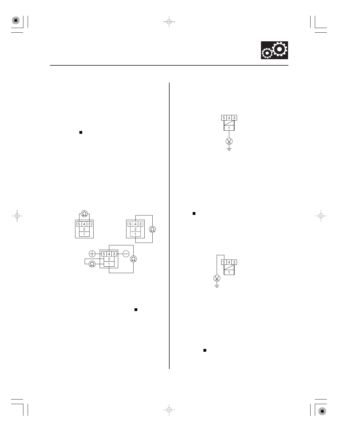
KEY INTERLOCK RELAY
KEY INTERLOCK RELAY CONNECTOR
KEY INTERLOCK RELAY CONNECTOR
1. Check the DTC P0705, P0706, and P0812 is
indicated.
Perform the troubleshooting for the indicated
code(s).
Go to step 2.
2. Turn the ignition switch OFF.
3. Remove the key interlock relay, and check for
continuity between these terminals:
• No. 3 and No. 5
• No. 1 and No. 4
• No. 1 and No. 2 while connecting battery voltage
to terminals No. 3 and No. 5, and also check for
no continuity between terminals No. 1 and No. 4.
Go to step 4.
Replace the key interlock relay.
4. Turn the ignition switch to the ACC (I) position.
5. Measure the voltage between the key interlock
relay connector terminal No. 1 and body ground.
Go to step 6.
Check for blown No. 8 fuse in the under-dash
fuse/relay box. If the fuse is OK, repair open in the
wire between the key interlock relay connector
terminal No. 1 and the under-dash fuse/relay
box.
6. Measure the voltage between the key interlock
relay connector terminal No. 5 and body ground.
Go to step 7.
Check for blown No. 8 (7.5 A) fuse in the
under-dash fuse/relay box. If the fuse is OK, repair
open in the wire between the key interlock relay
connector terminal No. 5 and the under-dash fuse/
relay box.
(cont’d)
Terminal side of male terminals
Wire side of female terminals
Wire side of female terminals
Does the HDS indicate code P07 05, P07 06, and
P0812?
Does the key inter lock r elay test OK ?
Is ther e batter y voltage?
Is ther e batter y voltage?
05/06/27 17:58:26 61S6M040_140_0326