Acura RSX Honda Integra. Manual - part 298


  Index      Acura     Acura RSX Honda Integra - service repair manual 2002-2006 year


Search            


Content   ..  296  297  298  299   ..


Acura RSX Honda Integra. Manual - part 298


01

02

03

S6M6APPE10436455201FAAT10

2005-2006 Models

YES

NO

YES

NO

YES

NO

YES

NO

14-317

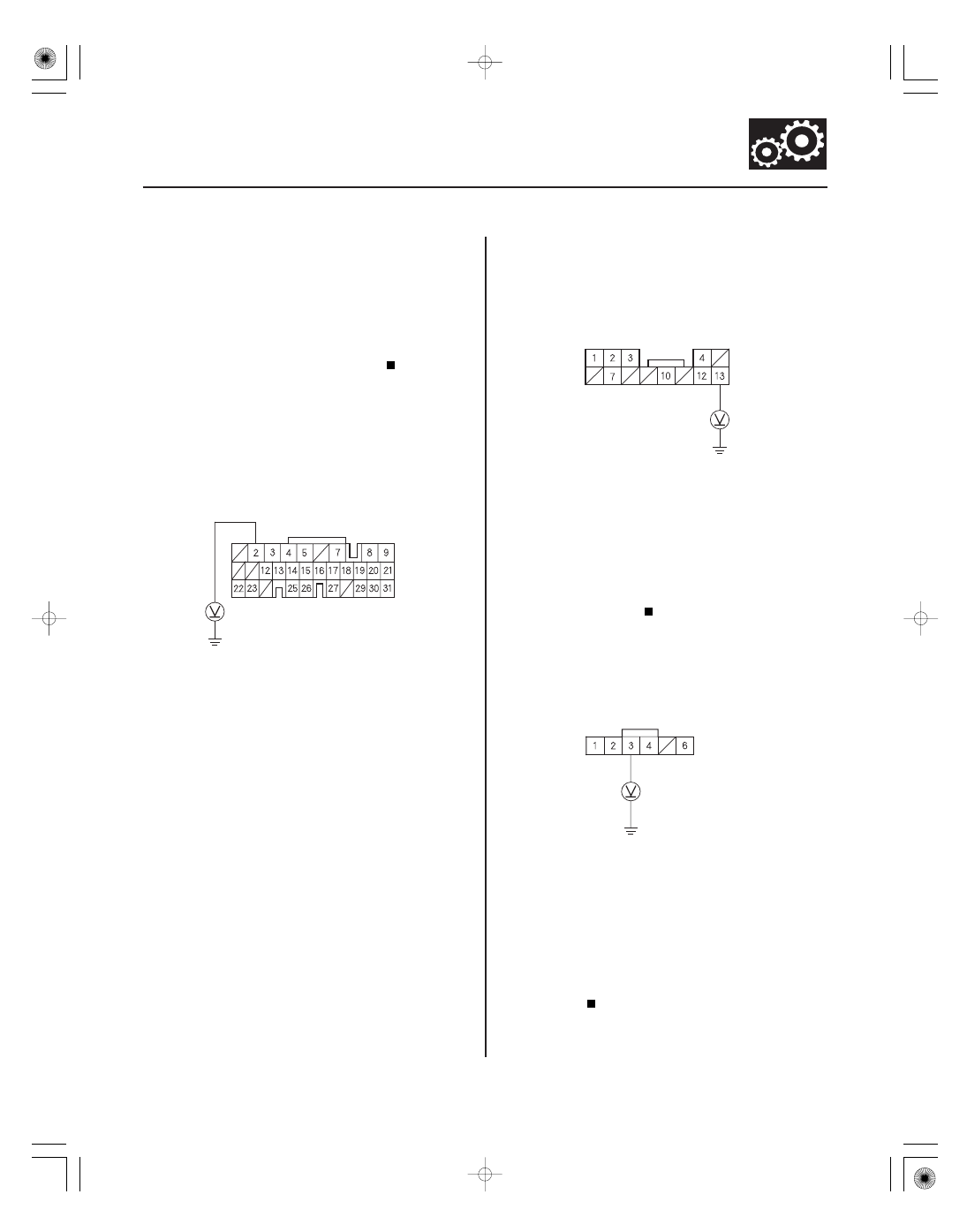
PCM CONNECTOR E (31P)

SLC (WHT/BLU)

No. 10 CONNECTOR (13P)

SLC (WHT/BLU)

No. 11 CONNECTOR (6P)

SHIFT LOCK SOLENOID
(YEL/BLK)

1. Press the brake pedal.

Go to step 2.

Repair faulty brake light circuit.

2. Turn the ignition switch ON (II), and shift to the P

position.

3. Press the brake pedal, release the accelerator pedal,

and measure the voltage between PCM connector
terminal E2 and body ground.

Go to step 4.

Go to step 8.

4. Remove the under-dash fuse/relay box from the

dash.

5. Measure the voltage between No. 10 connector

(13P) terminal No. 13 and body ground with the
accelerator pedal released and brake pedal pressed.

Go to step 6.

Repair open in the wire between PCM

connector terminal E13 and the multiplex control
unit (via the No. 10 connector (13P) of the under-
dash fuse/relay box).

6. Measure the voltage between No. 11 connector (6P)

terminal No. 3 of the under-dash fuse/relay box and
body ground.

Go to step 7.

Repair open in the wire between the shift lock

solenoid connector and multiplex control unit (via
the No. 11 connector (6P) of the under-dash fuse/
relay box).

(cont’d)

Wire side of female terminals

Wire side of female terminals

Wire side of female terminals

Ar e the br ake lights ON?

Is ther e 5 V

batter y voltage?

Is ther e 5 V

batter y voltage?

Is ther e 5 V

batter y voltage?

05/06/27 17:58:25 61S6M040_140_0318

*01

YES

NO

YES

NO

14-318

A/T Interlock System

Shift Lock System Circuit Troubleshooting (cont’d)

PCM CONNECTORS

A (31P)

LG1 (BRN/YEL)

E (31P)

BK SW (WHT/BLK)

7. Turn the ignition switch OFF, move the shift lever

to the P position, and then turn the ignition switch
ON (II).

Check for loose terminal fit in the under-dash

fuse/relay box connectors. If necessary, substitute
a known-good multiplex control unit and recheck.

Repair open in the P position wire between

the multiplex control unit and the transmission
range switch.

8. Turn the ignition switch OFF.

9. Jump the SCS line with the HDS.

10. Disconnect PCM connectors A (31P) and E (31P).

11. Press the brake pedal, and measure the voltage

between PCM connector terminal E22 and A9.

Release the brake pedal, and go to step 12.

Repair open in the wire between PCM

connector terminal E22 and the brake pedal
position switch.

12. Reconnect PCM connectors A (31P) and E (31P).

13. Turn the ignition switch ON (II).

Wire side of female terminals

Does the P indicator in the gauge assembly
illuminate?

Is ther e batter y voltage?

05/06/27 17:58:25 61S6M040_140_0319

*02

*03

*04

YES

NO

YES

NO

YES

NO

14-319

PCM CONNECTOR A (31P)

TPS (RED/BLK)

LG1 (BRN/YEL)

SG2
(GRN/YEL)

VCC2
(YEL/BLU)

TP SENSOR CONNECTOR

SG2 (GRN/YEL)

TP SENSOR CONNECTOR

14. Measure the voltage between PCM connector

terminal A29 and A9.

Go to step 19.

Go to step 15.

15. Turn the ignition switch OFF.

16. Disconnect the throttle position (TP) sensor

connector.

17. Turn the ignition switch ON (II).

18. Measure the voltage between TP sensor connector

terminals No. 1 and No. 3.

Check for an open or a short in the wire

between PCM connector terminal A29 and TP
sensor. If the wire is OK, replace the TP sensor.

Go to step 19.

19. Turn the ignition switch OFF.

20. Disconnect PCM connector A (31P).

21. Check for continuity between TP sensor connector

terminal No. 3 and body ground.

Check for a short to ground in the wire

between TP sensor connector terminal No. 3 and
PCM. If the wire is OK, replace the PCM.

Go to step 22.

(cont’d)

Wire side of female terminals

Wire side of female terminals

Wire side of female terminals

Is ther e about 0.5 V ?

Is ther e about 5 V ?

Is ther e continuity?

05/06/27 17:58:25 61S6M040_140_0320

08

09

YES

NO

YES

NO

14-320

A/T Interlock System

Shift Lock System Circuit Troubleshooting (cont’d)

SHIFT LOCK SOLENOID CONNECTOR

SHIFT LOCK
SOLENOID
(YEL/BLK)

SHIFT LOCK
SOLENOID
(YEL/RED)

SHIFT LOCK SOLENOID CONNECTOR

BLK

BRN

22. Disconnect shift lock solenoid connector.

23. Turn the ignition switch ON (II).

24. Measure the voltage between shift lock solenoid

connector terminals.

Go to step 25.

Check for blown No. 8 fuse in the under-dash

fuse/relay box. If the fuse is OK, repair open or
short in the wire between the shift lock solenoid
connector and the under-dash fuse/relay box.

25. Connect the battery positive terminal to shift lock

solenoid connector terminal No. 1, and connect the
battery negative terminal to terminal No. 2, then
check that the shift lock solenoid operates.

NOTE: Do not connect the battery positive terminal
to terminal No. 2 or you will damage the diode
inside the shift lock solenoid.

Check for an open in the wire between the

shift lock solenoid connector and the multiplex
control unit. If the wire is OK, check for a loose
terminal fit in the multiplex control unit connectors.
If necessary, substitute a known-good multiplex
control unit and recheck.

Replace the shift lock solenoid.

Wire side of female terminals

Terminal side of male terminals

Is ther e 5 V

batter y voltage?

Does the shif t lock solenoid oper ate pr oper ly?

05/06/27 17:58:25 61S6M040_140_0321


Content   ..  296  297  298  299   ..