Acura RL. Manual - part 438
 

  Index      Acura     Acura RL - service repair manual 2005-2008 year


Search            


Content   ..  436  437  438  439   ..


Acura RL. Manual - part 438


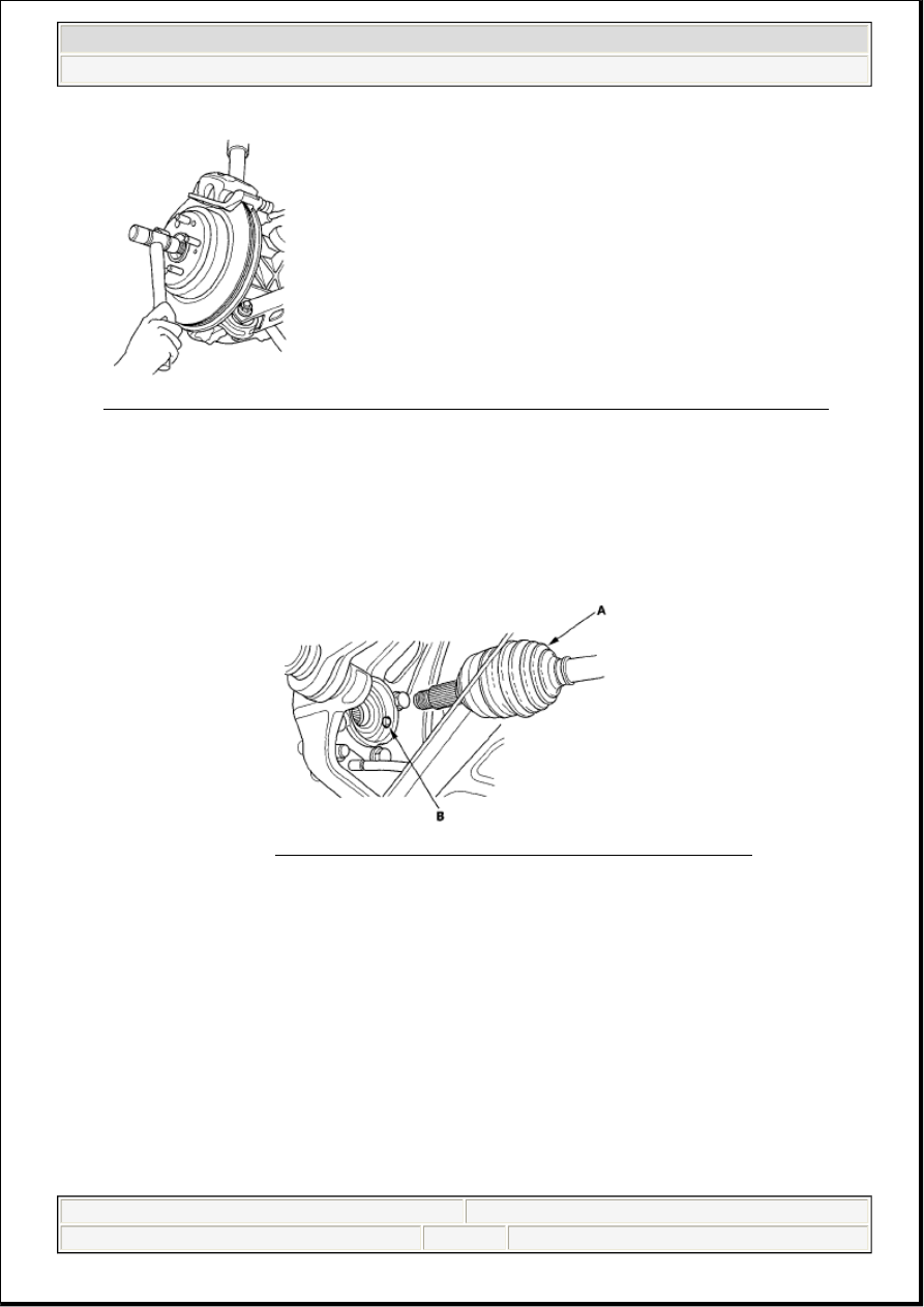
Fig. 82: Removing Rear Driveshaft Outboard Joint From The Trailing Arm And Rear Hub 
Courtesy of AMERICAN HONDA MOTOR CO., INC. 

6. Remove the rear driveshaft (A). 

REAR DRIVESHAFT DISASSEMBLY 

Special Tools Required  

Threaded adapter, 24 x 1.5 mm 07XAC-001020A  

Slide hammer, 5/8" x 18 UNF, commercially available  

INBOARD JOINT SIDE 

1. Remove the boot bands. Be careful not to damage the boot. 

If the boot band is a locking tab type (A), pry up the locking tab (B) with a screwdriver, and lift 
up the end of the band.  

If the boot band is a double loop type (C), lift up the band end (D), and push it into the clip (E). 

NOTE:

Be careful not to damage the wheel sensor (B).  

Pull on the outer joint. Do not pull on the driveshaft because the 
joint may come apart. 

Fig. 83: Identifying Rear Driveshaft And Wheel Sensor 
Courtesy of AMERICAN HONDA MOTOR CO., INC. 


2007 Acura RL 

2005-08 DRIVELINE/AXLES Driveline/Axle - RL


me 


Friday, June 05, 2009 3:01:08 PM

Page 38 

© 2005 Mitchell Repair Information Company, LLC. 

Locking tab type  

Fig. 84: Identifying Inboard Joint Side (Locking Tab Type) 
Courtesy of AMERICAN HONDA MOTOR CO., INC. 

Double loop type  

Fig. 85: Identifying Inboard Joint Side (Double Loop Type) 
Courtesy of AMERICAN HONDA MOTOR CO., INC. 

2. Remove the circlip (A). 

Fig. 86: Making Match Mark On Bearing Retainer And Inboard Joint 
Courtesy of AMERICAN HONDA MOTOR CO., INC.


2007 Acura RL 

2005-08 DRIVELINE/AXLES Driveline/Axle - RL


me 


Friday, June 05, 2009 3:01:08 PM

Page 39 

© 2005 Mitchell Repair Information Company, LLC. 

3. Make a mark (B) on the bearing retainer (C) and inboard joint (D) to identify the locations of ball 

bearings and grooves in the inboard joint. Then remove the inboard joint on the shop towel (E). Be 
careful not to drop the ball bearings when separating them from the inboard joint.  

4. Remove the snap ring (A). 

Fig. 87: Making Match Mark On Bearing Retainer, Bearing Race And Driveshaft 
Courtesy of AMERICAN HONDA MOTOR CO., INC. 

5. Make a mark (B) on the bearing retainer (C), the bearing race (D), and driveshaft (E) to identify the 

position of the bearing retainer and the bearing race on the shaft.  

6. Remove the bearing race and the steel ball bearings (F).  

7. Wrap the splines on the driveshaft (A) with vinyl tape (B) to prevent damage to the boot. 

Double loop type  

Fig. 88: Wrapping Splines On Driveshaft With Vinyl Tape (Double Loop Type) 
Courtesy of AMERICAN HONDA MOTOR CO., INC. 

Locking tab type  


2007 Acura RL 

2005-08 DRIVELINE/AXLES Driveline/Axle - RL


me 


Friday, June 05, 2009 3:01:08 PM

Page 40 

© 2005 Mitchell Repair Information Company, LLC. 

Fig. 89: Wrapping Splines On Driveshaft With Vinyl Tape (Locking Tab Type) 
Courtesy of AMERICAN HONDA MOTOR CO., INC. 

8. Remove the inboard boot (C) and locking tab type boot band (D). Be careful not to damage the boot.  

9. Remove the vinyl tape.  

OUTBOARD JOINT SIDE 

1. Remove the boot bands. Be careful not to damage the boot. 

If the boot band is a low profile type (A), pinch the boot band using commercially available 
boot band pliers (B).  

If the boot band is an ear clamp type (C), lift up the three tabs (D) with a screwdriver.  

Low profile type  

Fig. 90: Removing Boot Band (Low Profile Type) 
Courtesy of AMERICAN HONDA MOTOR CO., INC. 

Ear clamp type  


2007 Acura RL 

2005-08 DRIVELINE/AXLES Driveline/Axle - RL


me 


Friday, June 05, 2009 3:01:08 PM

Page 41 

© 2005 Mitchell Repair Information Company, LLC. 


Content   ..  436  437  438  439   ..