Kia Forte (2024 year). Manual in english - page 4
 

  Index      Kia     Kia Forte (2024 year). Manual in english


Search            copyright infringement  


Content      ..     2      3      4      5     ..


Kia Forte (2024 year). Manual in english - page 4


Features of your vehicle

28

4

Trunk

W ARNING

No one should be allowed to occupy the 
trunk at any time. The trunk is a very
dangerous location in an accident.

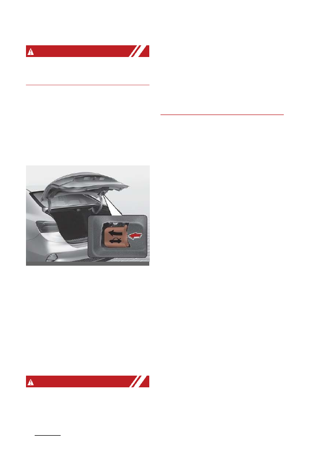
Emergency trunk safety release

Your vehicle is equipped with an emer

-

gency trunk release lever located inside 
the trunk. If someone is inadvertently 
locked in the trunk, moving the handle in 
the direction of the arrow will release the 
trunk latch mechanism and open the 
trunk.

• You and your passengers must be 

aware of the location of the emer

-

gency trunk safety release lever in this 
vehicle and how to open the trunk if 
accidentally locked in the trunk.

• Your vehicle should be kept locked 

and the smart key should be kept out 
of the reach of children. Parents 
should teach their children about the 
dangers of playing in trunks.

• Use the release lever for emergencies 

only.

W ARNING

NEVER allow anyone to occupy the 
trunk of the vehicle at any time. If the 
trunk is partially or totally latched and

the person is unable to get out, serious 
injury or death could occur due to lack of 
ventilation, exhaust fumes, rapid heat 
build-up, or because of exposure to cold 
weather. The trunk is also a highly dan

-

gerous location accident because it is 
not a protected occupant space but is a
part of the

vehicle’s crush zone.

OBD041041

29

4

4

Features of your vehicle

Smart Trunk

Smart Trunk (if equipped)

On a vehicle equipped with a smart key, 
the trunk can be opened using the Smart
Trunk system.

How to use the Smart Trunk

The trunk can be opened with no-touch 
activation under all the conditions below.

After 15 seconds when all doors are
closed and locked

• Positioned in the detecting area for 

more than 3 seconds.

NOTICE

The Smart Trunk does not operate
when:
• The smart key is detected within 15

seconds after the doors are closed,
locked and is continuously detected.

• The smart key is detected within 15 

seconds after the doors are closed 
and locked, and 60 inches (1.5 m) 
from the front door handles. (for vehi

-

cles equipped with Welcome Light)

• A door is not locked or closed.

The smart key is in the vehicle.

1. Setting

Make sure the shift lever is in P (Park) 
(for Dual Clutch Transmission/ Intelli

-

gent Variable Transmission) or first 
gear or R (Reverse) (for Manual 
Transmission) and set the parking 
brake.

You can activate or deactivate the 
Smart Trunk by selecting 'User Set

-

tings (LCD display) or Settings

Vehicle (Infotainment System screen)

→ Door → Smart Trunk'.

2. Detect and Alert

If you are positioned in the detecting 
area (20 ~ 40 inches (50 ~ 100 cm) 
behind the vehicle) carrying a smart 
key, the hazard warning lights will 
blink and the chime will sound to alert 
you the smart key has been detected 
and the trunk will open.

NOTICE

Do not approach the detecting area if 
you do not want the trunk to open. If you 
have unintentionally entered the detect

-

ing area and the hazard warning lights 
and chime starts to operate, leave the 
detecting area with the smart key. The 
trunk will stay closed.

OBD041042

OBDM041043

Features of your vehicle

30

4

Smart Trunk

3. Automatic opening

The hazard warning lights will blink 
and the chime will sound 2 times. The 
trunk will open.

• Make sure you close the trunk before 

driving your vehicle.

• Make sure there are no people or 

objects around the trunk before open

-

ing or closing the trunk.

• Make sure to deactivate the Smart 

Trunk when washing your vehicle. 
Otherwise, the trunk may open inad

-

vertently.

W ARNING

Make sure objects in the trunk do not fall
out when opening the trunk on a slope. It
may cause serious injury.

NOTICE

The key should be kept out of reach of 
children. Children may inadvertently 
open the Smart Trunk while playing 
around the rear area of the vehicle.

How to deactivate the Smart 
Trunk function using the smart 
key

1. Door lock

2. Door unlock

3. Trunk open

4. Panic

5. Remote start
If you press any button of the smart key 
during the Detect and Alert stage, the 
Smart Trunk function will be deacti

-

vated.

Be aware of how to deactivate the Smart 
Trunk function for emergency situations.

NOTICE

• If you press the door unlock button (2),

the Smart Trunk function will be 
deactivated temporarily. If you do not 
open any door for 30 seconds, the 
Smart Trunk function will be re-acti

-

vated.

• If you press the trunk open button (3) 

for more than 1 second, the trunk 
opens.

• If you press the door lock button (1) or

trunk open button (3) when the Smart
Trunk function is not in the Detect and
Alert stage, the Smart Trunk function
will not be deactivated.

OBDM041044L

ODL3A041656

31

4

4

Features of your vehicle

Smart Trunk

• In case you have deactivated the 

Smart Trunk function by pressing the 
smart key button and opening a door, 
the Smart Trunk function will be re-
activated by closing and locking all 
doors.

Detecting area

• The Smart Trunk operates with a wel

-

come alert if the smart key is detected 
within 20 ~ 40 inches (50 ~ 100 cm) 
of the trunk.

• The alert stops immediately if the 

smart key is outside the detecting 
area during the Detect and Alert 
stage.

NOTICE

• The Smart Trunk function will not 

work if any of the following occurs:

- The smart key is close to a radio 

transmitter such as a radio station 
or an airport which can interfere 
with normal operation of the trans

-

mitter.

- The smart key is near a two way 

radio system or mobile phone.

- Another

vehicle’s smart key is 

being operated near your vehicle.

• The detecting range may decrease or 

increase when :

- One of the tires is raised to replace 

a tire or to inspect the vehicle.

- The vehicle is parked on a slope or 

unpaved road, etc.

OBDM041045

Features of your vehicle

32

4

Windows

Windows

The doors of this vehicle are equipped with power windows that can be operated by a 
switch.

1. Driver's door power window switch

2. Front passenger's door power window switch

3. Rear door (left) power window switch

4. Rear door (right) power window switch

5. Window opening and closing

6. Automatic power window up*/down*

7. Power window lock button

*: if equipped

OBDM041046

33

4

4

Features of your vehicle

Windows

NOTICE

In cold and wet climates, power windows 
may not work properly due to freezing 
conditions.

Power windows

The ignition switch or ENGINE START/ 
STOP button must be in the ON position 
for power windows to operate.

Each door has a power window switch 
that controls the door's window. The 
driver has a power window lock button 
which can block the operation of rear 
passenger windows. The power windows 
can be operated for approximately 3
minutes after ignition switch or ENGINE 
START/STOP button turned to the ACC 
or LOCK/OFF position. If the front doors 
are opened, the power windows will not 
be operate even within the 3 minutes 
period.

The driver's door has a master power 
window switch that controls all the win

-

dows in the vehicle.If the window cannot 
be closed because it is blocked by 
objects, remove the objects and close 
the window.

W ARNING

Power windows
Do not extend your face or arms outside
of the window opening while the vehicle
is in motion. Doing so could result in sig

-

nificant injury.

NOTICE

While driving with the rear windows down
or with the sunroof (if equipped) in an
open (or partially open position), a wind
buffeting or pulsation noise. This noise is
normal and can be reduced or eliminated
by taking the following

actions. If the noise may occurs with one 
or both of the rear windows down, par

-

tially lower both front windows approxi

-

mately 1 inch (2.5 cm). If you experience 
the noise with the sunroof open, slightly 
reduce the size of the sunroof opening.

CAUTION

Do not install any accessories in the 
vehicle that extend into the open win

-

dow area. Such objects will impact the 
proper function of the Automatic rever

-

sal "jam protection" feature described in 
"Automatic reversal" section of this man

-

ual.

Window opening and closing

You

can open and close windows using the
power window switch.

To open or close a window, press down
or pull up the front portion of the corre

-

sponding switch to the first detent posi

-

tion (5).

OBD041084

Features of your vehicle

34

4

Windows

Auto down window (for driver's 
window) (if equipped)

Pressing the power window switch 
momentarily to the second detent posi

-

tion (6) completely lowers the window 
even when the switch is released. To 
stop the window at the desired position 
while the window is in operation, pull up 
the switch momentarily.

Auto up/down window (for 
driver's window) (if equipped)

Pressing or pulling up the power window 
switch momentarily to the second detent 
position (6) completely lowers or raises 
the window even when the switch is 
released. To stop the window at the 
desired position while the window is in

operation, pull up or press down and 
release the switch.

To reset the power windows

If the power window does not operate 
normally, the automatic power window 
system must be reset as follows:

1. Turn the ignition switch or ENGINE 

START/STOP button to the ON
posi

-

tion.

2. Close the window and continue pull

-

ing up the power window switch for at 
least 1 second after the window is 
completely closed.

Automatic reversal (for Auto up/
down window) (if equipped)

If the upward movement of the window 
is blocked by an object or part of the 
body, the window will detect the resis

-

tance and will stop upward movement. 
The window will then lower approxi

-

mately 11.8 inches (30 cm) to allow the 
object to be cleared.

If the window detects the resistance 
while the power window switch is pulled 
up continuously, the window will stop 
upward movement and lower approxi

-

mately 1 inch (2.5 cm).

The power window switch is pulled up 
continuously again within 5 seconds

OBD041405L

OBD041085

OJA040552

35

4

4

Features of your vehicle

Windows

after the window is lowered by the auto

-

matic window reversal feature, the auto

-

matic window reversal will not operate.

The automatic reverse feature for the 
window is only active when the "auto up" 
feature is used by fully pulling up the 
switch. The automatic reverse feature 
will not operate if the window is raised 
using the halfway position on the power 
window switch.

W ARNING

Always check for obstructions before 
raising any window to avoid injuries or 
vehicle damage. If an object less than
0.16 of an inch (4 mm) in diameter is 
caught between the window glass and 
the upper window channel, the auto

-

matic window reverse may not detect 
the resistance and will not stop and 
reverse direction.

W ARNING

The automatic reverse feature

doesn’t 

activate while resetting the power win

-

dow system. Make sure body parts or 
other objects are safely out of the way 
before closing the windows to avoid inju

-

ries or vehicle damage.

CAUTION

Do not install any accessories in the 
vehicle that extend into the open win

-

dow area. Such objects could prevent 
the automatic reverse feature from 
functioning.

Power window lock button

The driver can disable the power win

-

dow switches on the rear passengers' 
doors by pressing the power window 
lock button to the lock position 
(pressed).

When the power window lock button is 
pressed:
• The driver's master control can oper

-

ate all passengers' power windows.

• The front passenger's control can 

operate the front passenger's power 
window.

• The rear passengers' control cannot

operate the rear passenger's power
window.

CAUTION

Opening/closing Window
To prevent possible damage to the 
power window system, do not open or 
close two window or more at the same 
time. This will ensure fuse longevity.

Always double check to make sure all
arms, hands, head and other obstruc

-

tions are safely out of the way before
closing a window.

OBDM041047

Features of your vehicle

36

4

Windows

W ARNING

Power windows
Do not allow children to play with the 
power windows. Keep the power window 
lock button (on the

driver’s door) in the 

LOCK (pressed) position.

Remote window opening system 
(if equipped)

You can control the windows movement 
with the engine turned off.
• Press the door unlock button (1) for 

more than 3 seconds. The window 
moves down after the doors are 
unlocked, if you press the door unlock 
button (1).

The window movement stops, when 
you release the door unlock button (1).

You can activate or deactivate the 
remote window opening system by 
selecting 'User Settings (LCD display) or 
Settings

→ Vehicle (Infotainment System 

screen)

→ Door → Remote Window Con

-

trol'.

CAUTION

• The remote window opening function 

may abruptly stop, when you move 
away from your vehicle during opera

-

tion. Stay in close to your vehicle,

while monitoring the window move

-

ment.

• Be careful when using the remote 

window opening function, as the 
doors will be unlocked.

OBDM041671

37

4

4

Features of your vehicle

Hood

Hood

The hood serves as a cover for the 
engine compartment.

Open the hood if maintenance work 
needs to be performed in the engine 
compartment or if you need to look in 
the compartment.

Opening the hood

1. Pull the release lever to unlatch the 

hood. The hood should pop open 
slightly.

Open the hood after turning off the 
engine on a flat surface, shifting the 
shift lever to the P (Park) (for Dual 
Clutch Transmission/ Intelligent Vari

-

able Transmission) or first gear or R
(Reverse) (for Manual Transmission) 
and set the parking brake.

2. Go to the front of the vehicle, raise the 

hood slightly, push the secondary 
hood release lever (1) up and lift the 
hood (2).

3. Pull out the support rod.
4. Hold the hood opened with the sup

-

port rod(3).

W ARNING

Hot parts
Grasp the support rod by the area 
wrapped in rubber. The rubber will help 
prevent you from being burned by hot 
metal when the engine is hot.

OBD041048

OBDM041049L

OBD041086

Features of your vehicle

38

4

Hood

Hood open warning

The hood warning message will appear 
on the LCD display when hood is open.

The warning chime will operate when the
vehicle is being driven at or above 2
mph (3 km/h) with the hood open.

Closing the hood

1. Before closing the hood, check the 

following:
• All filler caps in the engine com

-

partment must be correctly 
installed.

• Gloves, rags or any other combusti

-

ble material must be removed from
the engine compartment.

2. Return the support rod to its clip to 

prevent it from rattling.

3. Lower the hood until it is about 12 

inches (30 cm) above the closed posi

-

tion and let it drop. Make sure that it 
locks into place.

4. Check that the hood has engaged 

properly.
• If the hood can be raise slightly, it is 

not properly engaged.

• Open it again and close it with a lit

-

tle more force.

CAUTION

Hood obstruction
Before closing the hood, ensure that all 
obstructions are removed from the hood 
opening. Closing the hood with an 
obstruction present in the hood opening 
may result in property damage.

W ARNING

Fire risk
Do not leave gloves, rags or any other 
combustible material in the engine com

-

partment. Doing so may cause a heat-
induced fire.

W ARNING

Unsecured engine hood
Always double check that the hood is 
firmly latched before driving. If it is not 
latched, the hood could fly open, caus

-

ing a total loss of visibility, which might 
result in an accident.

OBD041540

OBDM041678

39

4

4

Features of your vehicle

Fuel filler door

W ARNING

The support rod must be inserted com

-

pletely into the hole whenever you 
inspect the engine compartment. This 
will prevent the hood from falling and 
possibly injuring you.

Fuel filler door

Opening the fuel filler door

The fuel-filler door must be opened from 
inside the vehicle by pulling up on the 
fuel-filler door opener located on the front
floor area on the driver's seat.

If the fuel filler door does not open 
because ice has formed around it, tap 
lightly or push on the door to break the 
ice and release the door. Do not pry on 
the door. If necessary, spray an 
approved de-icer fluid around the door. 
Do not use radiator anti-freeze. You can 
also move the vehicle to a warm place 
and allow the ice to melt.

1. Stop the engine.
2. To open the fuel filler door, pull up the 

fuel filler door opener.

3. Pull open the fuel filler door (1).
4. To remove the cap, turn the fuel filler 

cap (2) counterclockwise.

5. Refuel as needed.

CAUTION

Before refueling, be sure to check what 
type of fuel is used for your vehicle.

If you put diesel fuel into a gasoline-
powered vehicle or gasoline into a die

-

sel-powered vehicle, it may affect the 
fuel system and cause serious damage 
to the vehicle.

Closing the fuel filler door

1. To install the cap, turn it clockwise 

until it

“clicks”. This indicates that the 

cap is securely tightened.

2. Close the fuel filler door and push it 

lightly and make sure that it is 
securely closed.

OBD041050

OBD041429

Features of your vehicle

40

4

Fuel filler door

W ARNING

Refueling
Always remove the fuel cap carefully 
and slowly. If the cap is venting fuel or if 
you hear a hissing sound, wait until the 
condition stops before completely 
removing the cap.

If pressurized fuel sprays out, it can 
cover your clothes or skin and subject 
you to the risk of fire and burns.

CAUTION

When refueling on unlevel ground, the 
fuel gauge may not point to the F (Full) 
position. It is not a malfunction. If you 
move your vehicle to a level ground, the 
fuel gauge will move to the F (Full) posi

-

tion.

NOTICE

Tighten the cap until it clicks one time or
the fuel cap open warning indicator light
will illuminate.

Always check that the fuel cap is 
installed securely to prevent fuel spillage 
in the event of an accident.

W ARNING

Fire/explosion risk
Read and follow all warnings posted at 
the gas station facility. Failure to follow 
all warnings will result in severe personal 
injury, severe burns or death due to fire 
or explosion.

W ARNING

Static electricity
• Before touching the fuel nozzle, you

should eliminate potentially danger

-

ous static electricity discharge by

touching another metal part of the 
vehicle, a safe distance away from the 
fuel filler neck, nozzle, or other gas 
source.

• Do not enter the vehicle once you 

have begun refueling since you can 
generate static electricity by touching, 
rubbing or sliding against any item or 
fabric (polyester, satin, nylon, etc.) 
capable of producing static electric

-

ity. Static electricity discharge can 
ignite fuel vapors resulting in rapid 
burning. If you must reenter the vehi

-

cle, you should once again eliminate 
potentially dangerous static electric

-

ity

discharge by touching a metal part of
the vehicle, away from the fuel filler 
neck, nozzle or other gasoline source.

W ARNING

Portable fuel container
When using an approved portable fuel 
container, be sure to place the container 
on the ground prior to refueling. Static 
electricity discharge from the container 
can ignite fuel vapors causing a fire.
Once refueling has begun, contact with
the vehicle should be maintained until the
filling is complete. Use only approved
portable plastic fuel contain

-

ers designed

to carry and store gasoline.

W ARNING

Mobile phone fires
Do not use mobile phones while refuel

-

ing. Electric current and/or electronic 
interference from mobile phones can 
potentially ignite fuel vapors causing a
fire.

41

4

4

Features of your vehicle

Sunroof

W ARNING

Refueling and vehicle fires
When refueling, always shut the engine 
off. Sparks produced by electrical com

-

ponents in the engine can ignite fuel 
vapors causing a fire. Once refueling is 
complete, check to make sure the filler 
cap and filler door are securely closed, 
before starting the engine.

W ARNING

Smoking
DO NOT use matches or a lighter and 
DO NOT SMOKE or leave a lit
cigarette in your vehicle while at a gas
station especially during refueling.
Automotive fuel is highly flammable and
can result in a fire when ignited.

Make sure to refuel your vehicle accord

-

ing to "Fuel requirements" on page 1-2.

If the fuel filler cap requires replace

-

ment, use only a genuine Kia cap or the 
equivalent specified for your vehicle. An 
incorrect fuel filler cap can result in a
serious malfunction of the fuel system or 
emission control system.

CAUTION

Exterior paint
Do not spill fuel on the exterior surfaces
of the vehicle. Any type of fuel spilled on
painted surfaces may damage the paint.

Sunroof (if equipped)

If your vehicle is equipped with a sun

-

roof, you can slide or tilt your sunroof
with the sunroof switch located on the
overhead console.

The sunroof can only be operated when 
the ignition switch or ENGINE START/ 
STOP button is in the ON or START
posi

-

tion.

The sunroof can be operated for 
approximately 3 minutes after the igni

-

tion switch or ENGINE START/STOP
but

-

ton is in the ACC or LOCK/OFF

position.

However, if the front door is open, the 
sunroof cannot be operated even within 
the 3 minute period.

W ARNING

• Adjust the sunroof or sunshade when 

your vehicle stops. This could result in 
loss of control and an accident that 
may cause injury, or property dam

-

age.

• Do not leave the engine running and 

the key in your vehicle with unsuper

-

vised children. Unattended children 
could operate the sunroof, which 
could result in serious injury.

• Do not sit on the top of the vehicle. It 

may cause injury or vehicle damage.

OCD041534L

Features of your vehicle

42

4

Sunroof

NOTICE

Do not operate the sunroof when roof 
bars are installed on the vehicle or when 
there is luggage on the roof.

Sunshade

Use the sunshade to block direct sun

-

light coming through the sunroof 
glass.Open or close the sunshade by 
hand.

INFORMATION

The sunshade opens automatically when 
the sunroof glass is opened, but the sun

-

shade does not close automatically
when the sunroof glass is closed. Also, 
the sunshade cannot be closed when the 
sunroof glass is opened.

NOTICE

Do not pull the sunshade up or down, or 
apply excessive force as such action 
may damage the sunshade or cause it to 
malfunction.

Tilt open/close

1. Tilt open

2. Tilt close
• Push the sunroof switch upward, the 

sunroof glass tilts open.

• Push the sunroof switch forward when

the sunroof glass is tilted open, the
sunroof glass closes.

The sunroof glass tilts open or closes 
while the switch is pushed.

INFORMATION

The sunroof glass cannot slide open and 
tilt open at the same time. You cannot
tilt the sunroof glass open while the sun

-

roof glass is slide open. Also, you cannot 
slide the sunroof glass open while the 
sunroof is tilt open. Slide open or tilt open
the sunroof glass when the sun

-

roof

glass is completely closed.

OBD041544

OBDM042684N

43

4

4

Features of your vehicle

Sunroof

Slide open/close

• Push the sunroof switch rearward, the 

sunshade and sunroof glass slide 
open. Push the sunroof switch for

-

ward, only the sunroof glass closes.

• Push the sunroof switch forward or 

rearward to the first detent position, 
the sunroof glass moves until the 
switch is released.

• Push the sunroof switch forward or 

rearward to the second detent posi

-

tion, the sunroof glass operates auto

-

matically (auto slide feature). To stop 
the sunroof movement at any point, 
push the sunroof switch in any direc

-

tion.

• The sunroof glass stops halfway (first 

detent position) before it is fully 
opened. To fully open the sunroof 
glass, push the sunroof switch rear

-

ward once more. At this time, the sun

-

roof glass opens only while the switch 
is pushed.

INFORMATION

To reduce wind noise while driving, we 
recommend that you drive at the recom

-

mended position (first detent position) 
before the maximum slide open position.

Automatic reversal

If the sunroof glass senses any obstacle 
while it is closing automatically, it will 
reverse direction then stop at a certain 
position.The auto reverse function may 
not work if an object thin or soft is caught
between the sliding sunroof glass and
sunroof sash.

W ARNING

• Make sure heads, hands, arms or any

other body parts or objects are out of
the way before operating the sunroof.
Body parts or objects may get caught
causing injuries or vehicle damage.

• Never deliberately use your body parts

to test the automatic reversal function.
The sunroof glass may reverse 
direction, but there is a risk of injury.

NOTICE

• Do not continue to push the sunroof 

switch after the sunroof is fully 
opened, closed, or tilted. Damage to 
the sunroof motor could occur.

• Continuous operations such as slide 

open/close, tilt open/close, etc. may 
cause the motor or sunroof system to 
malfunction.

OBDM041063L

OBD041542

Features of your vehicle

44

4

Sunroof

• Regularly remove any accumulated 

dust on the sunroof rail.

• Dust accumulated between the sun

-

roof and roof panel can make noise. 
Open the sunroof and remove dust 
regularly using a clean cloth.

• Do not try to open the sunroof when 

the temperature is below freezing or 
when the sunroof is covered with 
snow or ice. The sunroof may not 
work properly and may break if 
opened by force.

• Do not open or drive with the sunroof 

glass open immediately after rain or 
washing the vehicle. Water may wet 
the interior of the vehicle.

• Do not extend any luggage outside 

the sunroof while driving. Vehicle 
damage may occur if the vehicle sud

-

denly stops.

W ARNING

Do not extend your head, arms, body 
parts or objects outside the sunroof 
while driving. Injuries may occur if the 
vehicle suddenly stops.

Resetting the sunroof

In some circumstances resetting the 
sunroof operation may need to be per

-

formed. Some instances where resetting 
the sunroof may be required include:
• When the 12-volt battery is either dis

-

connected or discharged

• When the sunroof fuse is replaced
• If the sunroof one-touch AUTO OPEN/ 

CLOSE operation is not functioning 
properly

Sunroof resetting procedure:
1. It is recommended to perform the 

reset procedure with the vehicle 
engine running. Start the vehicle in P
(Park).

2. Make sure the sunroof glass is in the 

fully closed position. If the sunroof 
glass is open, push the switch forward 
until the sunroof glass is fully closed.

3. Release the switch when the sunroof 

glass is fully closed.

4. Push the switch forward until the sun

-

roof glass moves slightly. Then
release the switch.

5. Once again push and hold the sun

-

roof switch forward until the sunroof 
glass slides open and closed.

Do not release the switch until the 
operation is completed. If you release 
the switch during operation, start the 
procedure again from step 2.

INFORMATION

If the sunroof does not reset when the
vehicle battery is disconnected or dis

-

charged, or the sunroof fuse is blown,
the sunroof may not operate normally.

OCD041538L

45

4

4

Features of your vehicle

Steering wheel

Sunroof open warning (if
equipped)

If the driver turns off the engine when the
sunroof is not fully closed, the warn

-

ing

chime will sound for several seconds and
the sunroof open warning will appear on
the cluster LCD display.

Close the sunroof securely when leaving 
your vehicle.

CAUTION

Make sure the sunroof is closed fully 
when leaving your vehicle. If the sunroof 
is left open, rain or snow may wet the 
interior of the vehicle. Also, leaving the 
sunroof open when the vehicle is unat

-

tended may invite theft.

Steering wheel

The steering wheel of this vehicle is 
equipped with the Motor Driven Power 
Steering (MDPS) system.

Motor Driven Power Steering 
(MDPS)

Power steering uses the motor to assist 
you in steering the vehicle.

If the engine is off or if the power steer

-

ing system becomes inoperable, the 
vehicle may still be steered, but will 
require increased steering effort.

The MDPS is controlled by the power 
steering control unit which senses the 
steering wheel torque and vehicle speed 
to command the motor.

The steering effort becomes heavier as 
the vehicle's speed increases and 
becomes lighter as the vehicle's speed 
decreases for better control of the steer

-

ing wheel.

Should you notice any change in the 
effort required to steer during normal 
vehicle operation, have the power steer

-

ing checked by an authorized Kia dealer.

NOTICE

The following symptoms may occur 
during normal vehicle operation:
• The MDPS warning light does not illu

-

minate.

• The Steering effort is heavy immedi

-

ately after turning the ignition switch or
ENGINE START/STOP button on. 
This happens as the MDPS system 
performs the diagnostics. When the 
diagnostics is completed, the steering 
effort will return to its normal condi

-

tion.

• A click noise may be heard from the 

MDPS relay after the ignition switch or 
ENGINE START/STOP button is

OBD041288

Features of your vehicle

46

4

Steering wheel

turned to the ON or LOCK/OFF posi

-

tion.

• A motor noise may be heard when the

vehicle is at a stop or at a low driving
speed.

• The Steering effort increases if the 

steering wheel is rotated continu

-

ously when the vehicle is not in 
motion. After a few minutes, it will 
return to its normal condition.

• When the charging system warning 

light comes on due to low voltage 
(when the alternator or battery do not 
operate normally or malfunction), the 
steering wheel may require increased 
steering effort.

• When you operate the steering wheel 

in low temperature, abnormal noise 
could occur. If temperature rises, the 
noise will disappear. This is a normal 
condition.

If the Motor Driven Power Steering Sys

-

tem does not operate normally, the 
warning light will illuminate on the 
instrument cluster.The power steering 
system will not operate and steering 
effort can increase. Take your vehicle to 
an authorized Kia dealer and have the 
vehicle checked as soon as possible.

Tilt & telescopic steering wheel

A

tilt and telescopic steering wheel allows
you to adjust the steering wheel
before you drive. You can also raise it to
give your legs more room when you exit
and enter the vehicle.

The steering wheel should be positioned 
so that it is comfortable for you to drive, 
while permitting you to see the instru

-

ment panel warning lights and gauges.

W ARNING

Steering wheel adjustment
Never adjust the angle and height of the 
steering wheel while driving. You may
lose steering control.

Adjusting steering wheel angle 
and height

1. To change the steering wheel angle, 

pull down the lock release lever (1).

2. Adjust the steering wheel to the 

desired angle (2) and height (3). Move 
the steering wheel, so it points toward 
your chest, not toward your face. 
Make sure you can see the instrument 
panel warning lights and gauges.
After adjusting, pull up the lock.

3. Pull up the lock-release lever to lock

the steering wheel in place. Push the
steering wheel both up and down to
be certain it is locked in position.

4. Be sure to adjust the steering wheel to

the desired position before driving.

NOTICE

After adjustment, sometimes the lock-
release lever may not lock the steering
wheel.

It is not a malfunction. This occurs when
two gears engage. In this case, adjust

OBD041066

47

4

4

Features of your vehicle

Steering wheel

the steering wheel again to lock the 
steering wheel.

Heated steering wheel (if
equipped)

When the ignition switch is in the ON 
position or the ENGINE START/STOP 
button is in the ON position, pressing the 
heated steering wheel button warms the 
steering wheel. The indicator on the but

-

ton will illuminate.

To turn the heated steering wheel off, 
press the button once again. The indica

-

tor on the button will turn off.

NOTICE

The heated steering wheel will turn off 
automatically approximately 30 min

-

utes after the heated steering wheel is 
turned on.

CAUTION

• Do not install any type of grip cover 

for the steering wheel. It may impair 
the function of the heated steering 
wheel system.

• When cleaning the heated steering 

wheel, do not use an organic solvent 
such as paint thinner, benzene, alco

-

hol or gasoline. Doing so may damage 
the surface of the steering wheel.

• If the surface of the steering wheel is 

stuck by a sharp object, damage to 
the heated steering wheel compo

-

nents could occur.

W ARNING

If the steering wheel becomes too warm, 
turn the system off. The heated steering 
wheel may cause burns even at low tem

-

peratures, especially if used for a long 
time.

Horn

To sound the horn, press the area indi

-

cated by the horn symbol on your steer

-

ing wheel (see illustration).

The horn will operate only when this area
is pressed. Check the horn regularly to be
sure it operates properly.

OBD041067

OBD041068

Features of your vehicle

48

4

Mirrors

Mirrors

This vehicle is equipped with inside and 
outside rear-view mirrors to provide 
views of objects behind the vehicle.

Inside rear view mirror

Adjust the rear view mirror so that the 
center view through the rear window is 
seen.

Make this adjustment before you start 
driving.

Do not place objects in the rear seat or 
cargo area which could interfere with 
your vision out the rear window.

W ARNING

Mirror adjustment
Do not adjust the rearview mirror while 
the vehicle is moving. This could result in 
loss of control.

W ARNING

Do not modify the rearview mirror and 
don't install a wide mirror. It could result in
injury during an accident or deploy

-

ment

of the air bag.

Day/night rear view mirror (if
equipped)

(A)

: Day, (B): Night

Make this adjustment before you start 
driving and while the day/night lever (1) 
is in the day position (A).

Pull the day/night lever (1) toward you

(B)

to reduce the glare from the head

-

lights of the vehicles behind you when
during night driving.

Remember that you lose some rear-view
clarity in the night position (B).

Day/night rearview mirror with 
Telematics function (if equipped)

For day and night function:

*(1): Day, (2): Night

OBD041069

OBDM041670

49

4

4

Features of your vehicle

Mirrors

Make this adjustment before you start 
driving and while the day/night lever is 
in the day position (1).

Pull the day/night lever toward you (2) to 
reduce the glare from the headlights of 
the vehicles behind you when night driv

-

ing.

Remember that you lose some rearview 
clarity in the night position (2).

For Telematics button function:

Telematics buttons are also located on 
the mirror.

1. Virtual Assist button

2. Kia connect button

3. Roadside assist button

Electric Chromic Mirror (ECM) (if
equipped)

The electric rear view mirror automati

-

cally controls the glare from headlights of
vehicles behind you in nighttime or in low
light driving conditions. The sensor 
mounted in the mirror senses the light 
level around the vehicle, and automati

-

cally controls the headlight glare from the
vehicles behind you.When the engine is
running, the glare is automati

-

cally

controlled by the sensor mounted in the
rearview mirror.Whenever the shift lever
is shifted into R (Reverse), the

mirror will automatically move to the 
brightest setting to improve the

driver’s 

view behind the vehicle.

CAUTION

When cleaning the mirror, use a paper 
towel or similar material dampened with 
glass cleaner. Do not spray glass cleaner 
directly on the mirror. It may cause the 
liquid cleaner to enter the mirror hous

-

ing.

To operate the electric rearview mirror:

The mirror defaults to the ON position
whenever the ignition switch is turned
on.

• Press the ON/OFF button (1) to turn

the automatic dimming function off.
The mirror indicator light (2) will turn
off.

• Press the ON/OFF button (1) to turn

the automatic dimming function on.
The mirror indicator light (2) will illu

-

minate.

*(2) : Indicator, (3) : Sensor

When the engine is running, the glare is
automatically controlled by the sensor
(3) mounted in the rear view mirror.

OBDM042685N

OBD041578L

Features of your vehicle

50

4

Mirrors

Electric Chromic Mirror (ECM) 
with Telematics function (if
equipped)

1. Virtual Assistant button

2. Kia connect button

3. Roadside assist button

4. Sensor
The electric rearview mirror automati

-

cally controls the glare from the head

-

lights of the vehicles behind you in 
nighttime or low light driving conditions.

The sensor (4) mounted in the mirror 
senses the light level around the vehicle, 
and automatically controls the headlight 
glare from the vehicles behind you.

When the engine is running, the glare is 
automatically controlled by the sensor 
mounted in the rearview mirror.

Telematics buttons are also located on 
the mirror.

Outside rear view mirror

Be sure to adjust the mirror angles 
before driving.

Your vehicle is equipped with both left 
side and right side outside rearview mir

-

rors. The mirrors can be adjusted 
remotely with the remote switch. The 
mirror heads can be folded back to pre

-

vent damage in an automatic car wash 
or when passing through a narrow street.

The right outside rearview mirror is con

-

vex. Objects seen in the mirror are closer
than they appear.

Use your interior rearview mirror or
direct observation to determine the
actual distance of following vehicles
when changing lanes.

CAUTION

Rearview mirror
Do not scrape ice off the mirror face. 
This may damage the surface of the 
glass. If ice restricts the movement of the 
mirror, do not force the mirror for 
adjustment. To remove ice, use a deicer 
spray, a sponge or soft cloth with very 
warm water.

If the mirror is jammed with ice, do not 
adjust the mirror by force. Use an 
approved spray de-icer (not radiator 
antifreeze) to release the frozen mecha

-

nism or move the vehicle to a warm 
place and allow the ice to melt.

W ARNING

Mirror adjustment
Do not adjust or fold the outside rear

-

view mirrors while the vehicle is moving. 
This could result in loss of control.

OBDM042460N

51

4

4

Features of your vehicle

Mirrors

Adjusting the outside rear view 
mirrors

The electric remote control mirror switch 
allows you to adjust the position of the 
left and right outside rear view mirrors.

Adjusting the rear view mirrors:
1. Move the R or L switch (1) to select the 

right side mirror or the left side mirror.

2. Press a corresponding point (

▲ ) on 

the mirror adjustment control (2) to 
position the selected mirror up, down, 
left or right.

CAUTION

Outside mirror
• The mirrors stop moving when they 

reach the maximum adjusting angles, 
but the motor continues to operate 
while the switch is pressed. Do not 
press the switch longer than neces

-

sary. The motor may be damaged.

• Do not adjust the outside rear view 

mirror by hand. Doing so may dam

-

age its parts.

• When adjusting the mirror control 

switch, press the

“▲” (2) marking 

area. Otherwise, the mirror will move 
to an unintended direction or mal

-

function.

Folding the outside rearview mir

-

ror

Manual type

To fold the outside rear view mirror, 
grasp the housing of the mirror and fold it
toward the rear of the vehicle.

OBDM041075

OBD041074L

Features of your vehicle

52

4

Instrument cluster

Instrument cluster

1. Tachometer

2. Speedometer

3. Engine coolant temperature gauge

4. Fuel gauge

5. LCD display

6. Warning and indicator lights
*Your instrument cluster may differ from the illustration. For more details, refer to the 

"Gauges" on page 4-53.

OBDM042264N

53

4

4

Features of your vehicle

Instrument cluster

Instrument Cluster Control

Adjusting Instrument Cluster Illu

-

mination

W ARNING

Never adjust the instrument cluster while
driving. This could result in loss of control
and lead to an accident that may cause
death, serious injury, or property 
damage.

The brightness of the instrument panel 
illumination is changed by pressing the 
illumination control button 

(“+” or “-”) 

when ignition switch or the ENGINE 
START/STOP button is ON, or the tail

-

lights are turned on.

• If you hold the illumination control 

button

(“+” or “-”), the brightness will 

be changed continuously.

• If the brightness reaches the maxi

-

mum or minimum level, an alarm will 
sound.

Gauges

Speedometer

The speedometer indicates the speed of 
the vehicle and is calibrated in miles per 
hour (mph) and/or kilometers per hour 
(km/h).

Tachometer

OBDM041080L

OBD041569L

OBDM042290N

OBDM042272N

Features of your vehicle

54

4

Instrument cluster

The tachometer indicates the approxi

-

mate number of engine revolutions per 
minute (rpm).

Use the tachometer to select the correct
shift points and to prevent lugging and/
or over-revving the engine.

CAUTION

Do not operate the engine within the 
tachometer's RED ZONE. This may
cause severe engine damage.

Engine Coolant Temperature 
Gauge

This gauge indicates the temperature of 
the engine coolant when the ignition 
switch or the ENGINE START/STOP
but

-

ton is ON.

CAUTION

If the gauge pointer moves beyond the 
normal range area (between the C-H) 
toward the

“H (Hot)” position, it indicates 

overheating that may damage the 
engine.

Do not continue driving with an over

-

heated engine. If your vehicle overheats, 
refer to "If the engine overheats" on
page 7-7.

W ARNING

Never remove the radiator cap when the 
engine is hot. The engine coolant is 
under pressure and could severely burn 
you. Wait until the engine is cool before 
adding coolant to the reservoir.

Fuel Gauge

This gauge indicates the approximate 
amount of fuel remaining in the fuel 
tank.

NOTICE

• The fuel tank capacity can be found in

"Recommended lubricants and capac

-

ities" on page 9-7.

• The fuel gauge is supplemented by a

low fuel warning light, which will illu

-

minate when the fuel tank is nearly 
empty.

• On inclines or curves, the fuel gauge 

pointer may fluctuate or the low fuel 
warning light may come on earlier 
than usual due to the movement of 
fuel in the tank.

OBDM042623N

OBDM042276N

55

4

4

Features of your vehicle

Instrument cluster

W ARNING

Fuel Gauge
Running out of fuel can expose vehicle 
occupants to danger.

You must stop and obtain additional fuel 
as soon as possible after the warning 
light illuminates or when the gauge indi

-

cator is close to the

“E (Empty)” level.

CAUTION

Avoid driving with an extremely low fuel 
level. Running out of fuel could cause
the engine to misfire damaging the cata

-

lytic converter.

NOTICE

The fuel display may not be accurate if 
the vehicle is on an incline.

Odometer

The odometer Indicates the total dis

-

tance that the vehicle has been driven 
and should be used to determine when 
periodic maintenance should be per

-

formed.
• Odometer range: 0 ~ 999,999 mi or 0

~ 1,599,999 km

Distance to empty

• The distance to empty is the esti

-

mated distance the vehicle can be 
driven with the remaining fuel.

- Distance range: 1 ~ 9,999 mi or 1 ~
9,999 km.

• If the estimated distance is below 1mi. 

(1 km), the trip computer will display

“-

--

” as distance to empty.

CAUTION

• If the vehicle is not on level ground or 

the battery power has been inter

-

rupted, the distance to empty function 
may not operate correctly.

• The distance to empty may differ from

the actual driving distance as it is an
estimate of the available driving 
distance.

• The trip computer may not register 

additional fuel if less than 1.6 gallons 
(6 liters) of fuel are added to the vehi

-

cle.

• The distance to empty may vary sig

-

nificantly based on driving condi

-

tions, driving habits, and condition of 
the vehicle.

OBDM042570N

OBDM042573N

Features of your vehicle

56

4

Instrument cluster

Outside Temperature

This gauge indicates the current outside 
air temperatures within 1

°F (1°C).

• Temperature range: -40°F ~ 140°F (-

40

°C ~ 60°C)

The outside temperature on the display 
may not change immediately like a regu

-

lar thermometer to prevent the driver from
being inattentive.

The temperature unit (from 

°C to °F or 

from

°F to °C) can be changed by:

- User Settings mode in the Cluster 

(if equipped): You can change 
the temperature unit in the 
“Other - Temperature unit”.

*For more details, refer to "LCD dis

-

play" on page 4-58.

- Climate control system (for Auto

-

matic climate control system):
While pressing the OFF button, 
press the AUTO button for 3 sec

-

onds or more. The temperature unit 
of the instrument cluster and cli

-

mate control system will change.

Transmission Shift Indicator

Intelligent variable transmission 
Shift indicator (if equipped)

This indicator displays which Intelligent 
variable transmission shift lever is 
selected.
• Park: P
• Reverse: R
• Neutral: N

Drive: D

• Sports Mode: S
• Manual Mode: 1,2,3,4,5,6

OBDM042574N

OBD041624L

57

4

4

Features of your vehicle

Instrument cluster

Manual Transmission Shift Indica

-

tor (if equipped)

This indicator informs which gear is rec

-

ommended while driving to save fuel.
• Shifting up:

2

,

3

,

4

,

5

,

6

• Shifting down:

1

,

2

,

3

,

4

,

5

For example

3

: Indicates that shifting up to the 3rd

gear is recommended (currently the shift
lever is in the 2nd or 1st gear).

4

: Indicates that shifting down to the 

4th gear is recommended (currently the 
shift lever is in the 5th or 6th gear).

When the system is not working prop

-

erly, the indicator will not display.

Dual clutch transmission shift 
indicator (if equipped)

This indicator displays which shift lever 
is selected.
• Park: P
• Reverse: 
R

Neutral: 

N
• Drive: D1, D2, D3, D4, D5, D6, D7
• Sports Mode: S

OBDM041612L

OMQ4040519L

Features of your vehicle

58

4

LCD display

LCD display

LCD Display Control

The LCD display modes can be
changed by using the control buttons on
the steering wheel.

1 .

: MODE button for change the

LCD MODES

2.

/

: MODE scroll switch for select 

the items

3. OK: SET/RESET button for the set

the items or reset the items

LCD display modes

The information provided may differ depending on which functions are applicable to 
your vehicle.

*For controlling the LCD modes, refer to "LCD Display Control" on page 4-

58“.

OBD041598

Mode

Driving Assist

Trip Computer

Turn By Turn (TBT)*

User Settings*

Master warning

Up/Down

Lane Keeping Assist/

Smart Cruise Control/
Lane Following Assist/
Highway Driving Assist

Drive Info

Route Guidance

Driver Assistance

The Master Warning

mode displays warn

-

ing messages related

to the vehicle when

one or more systems

is not operating nor

-

mally.

Since Refueling

Destination Info

Cluster

Accumulated Info

Lights

Digital Speedometer

Door

Driver Attention Warn

-

ing

Convenience

Units

Language

Reset

59

4

4

Features of your vehicle

LCD display

Driving Assist mode

• Lane Keeping Assist (if equipped) 

Smart Cruise Control (if
equipped)Lane Following Assist (if 
equipped)Highway Driving Assist (if
equipped)

• Driver Attention Warning (if equipped)
*For more details, refer to each

system’s 

information in "Driving your vehicle" on
page 5-4.

Setting (if equipped)

To change the Driver Assistance set

-

tings, press the OK button on the steer

-

ing wheel for more than 1 second when 
the Driving Assist mode is displayed.

W ARNING

While driving, do not change the set

-

tings. It may distract your attention and 
cause an accident.

NOTICE

The information provided may differ 
depending on which functions are appli

-

cable to your vehicle.

Trip computer mode

The trip computer mode displays infor

-

mation related to vehicle driving param

-

eters including Accumulated info, Driving
information, etc.

*For more details, refer to "Trip Com

-

puter" on page 4-69.

OBD041580

Item

Explanation

SCC Reaction

Fast/Normal/Slow

Warning Timing

Normal/Late

Warning Volume

High/Medium/Low

Driver Attention
Warning

Leading Vehicle Departure Alert/Inat

-

tentive Driving Warning

Forward Safety

Active Assist/Warning Only/Off

Lane Safety

Assist/Warning Only/Off

Blind-Spot Safety

Safe Exit Warning/Active Assist/Warn

-

ing Only/Off

Parking Safety

Rear Cross-Traffic Safety

OBDM042297N


Content      ..     2      3      4      5     ..