Inspection Plus software for Haas machining centres. Programming manual (H-2000-6222-0A-B) - page 5
Additional cycles
9-33
Updating the SPC tool offset - macro O9835
Cc
Cc
Run of measurements out of
limit prior to correction.
x
x x
x
+
x
x
x
Vv
x x
x
Nominal size
Vv
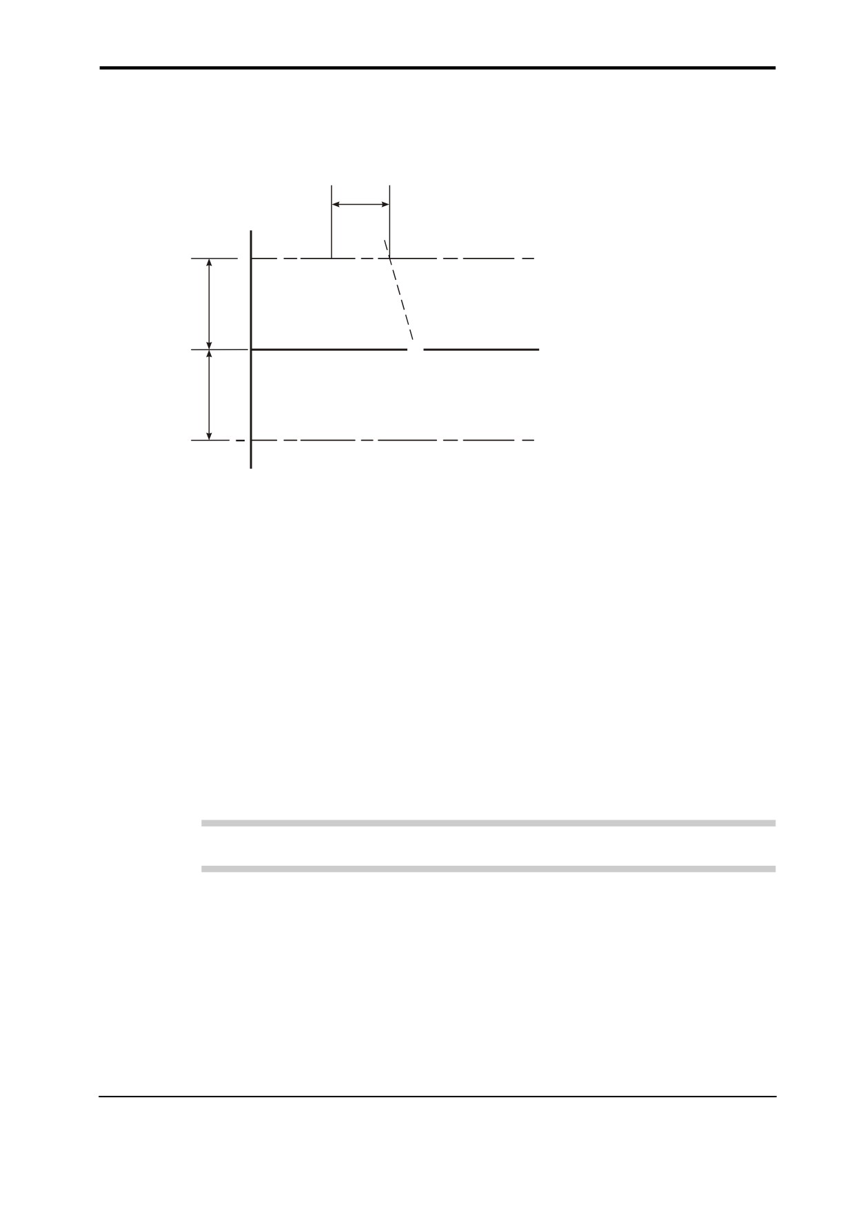
Figure 9.18 Updating the SPC tool offset
Description
This macro can be used in conjunction with measuring cycles to control tool offset
updates. It offers the possibility of providing an update based on the average value of a
sample of measurements.
Application
A measuring cycle should be run, but with no tool offset update (Tt input). A component
tolerance (Hh input) can be used if required. The SPC macro should follow. An average
value is accumulated until a specified continuous run of values are outside the control
limit. At this point the tool offset is updated, based on the average value.
IMPORTANT: Set the Mm store tool offsets to 0 on the offset page prior to use.
Format
G65P9835 Tt Mm [Vv Cc Ff Zz]
where [ ] denote optional inputs
Example: G65 P9835 T20. M0.2 V0.25 C4 F0.8 Z1.
Publication No. H-2000-6222
9-34
Additional cycles
Compulsory inputs
Tt
t =
Tool offset number for updating.
Mm m = Spare tool offset pair for storing average value and counter.
m
= Accumulated average value store location.
m+1
= Counter store location.
Optional inputs
Cc
c = Number of measurements out of tolerance before corrective action is
taken (default = 3).
Ff
f =
See Chapter 3, “Optional inputs”.
Vv
v = See Chapter 3, “Optional inputs”.
Zz
z = Flag for Z length offset update. A Z value needs to be input to force the
length offset register to be updated, otherwise the radius register will be
updated.
NOTE: This input is only necessary when using type 'C' tool offset option.
Example
SPC tool offset updating
From previous
G65P9814D50.H.5
Measure bore to 0.5 mm (0.0197 in) tolerance.
G65P9835T30.M31.V.1C4. T30 = Tool offset number for updating.
M31. = Spare tool offsets pair (31 and 32).
V.1 = Control limit.
C4. = Run of measurements out of limit.
Continues
Publication No. H-2000-6222
Additional cycles
9-35
Optimising a probing cycle - macro O9836
(b)
(a)
(c)
Z
#562
x
Qq
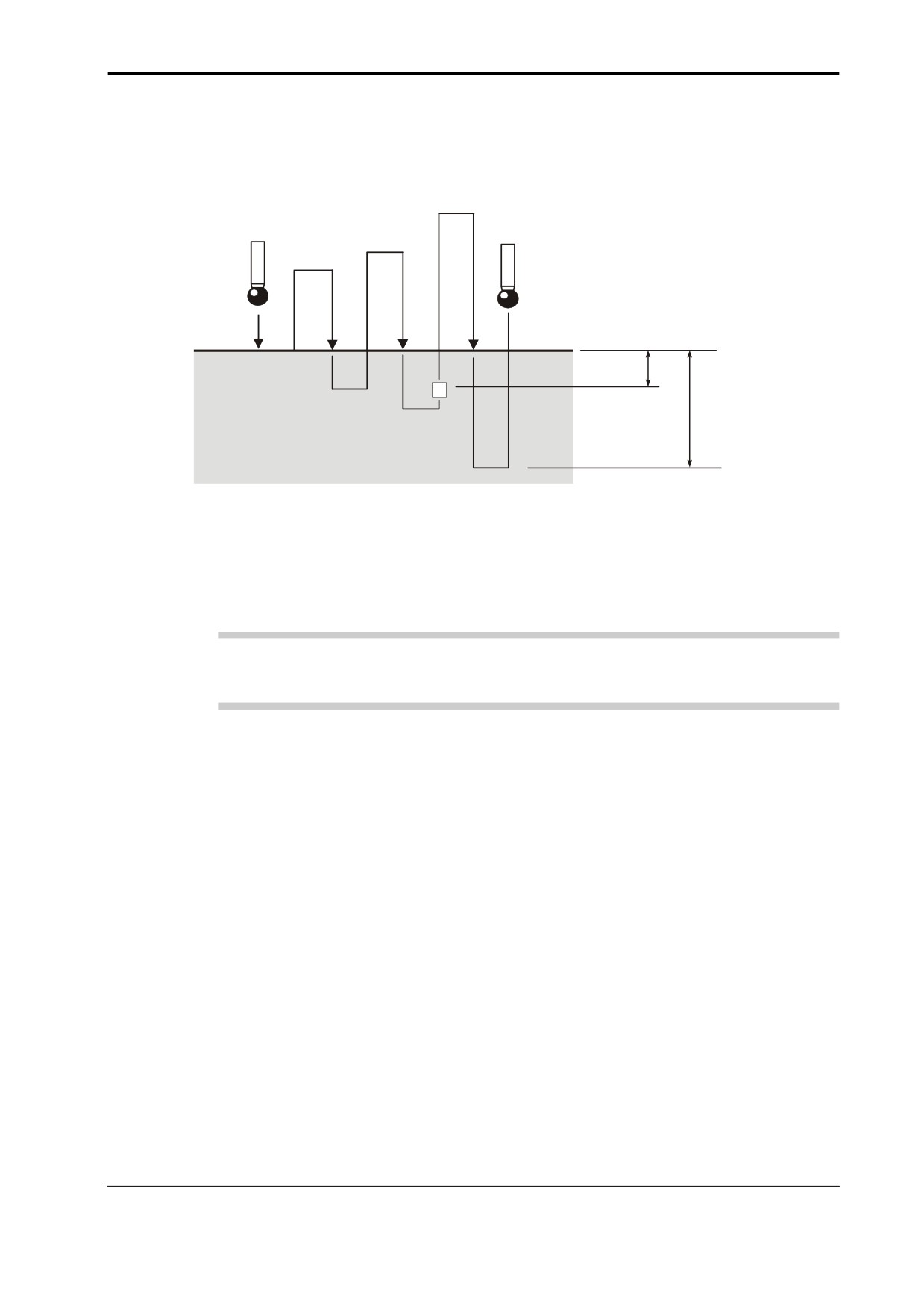
a = Start at 30 mm/min (1.181 in/min)
b = #169*.6 feedrate
c = Maximum feedrate
Figure 9.19 Optimising a probing cycle
NOTE: For small and medium machines the default values for feedrate and back-off
distance are adequate. Therefore it is not essential to run this macro in every case.
Description
This macro is used to establish the optimum maximum feedrate and back-off distance
values for the probing cycles.
Application
1.
The probe should be made active. At this stage the turn-on macro for the optical
probe may not be functioning. Therefore, use the MDI mode and turn the probe by
using the appropriate M-code.
2.
Position the probe stylus within 2 mm (0.08 in) of the surface. Call this macro within
a small program, and run the cycle.
The probe moves towards the Z surface at 30 mm/min. (1.2 in). The cycle continues to
retract and find the surface several times to establish the optimum values.
At the end, the cycle returns to the start position.
Publication No. H-2000-6222

9-36
Additional cycles
NOTE: The repeat surface finding moves get progressively faster until the maximum
overtravel is reached. Also, the retract position off the surface increases. It is important,
therefore, that you allow for adequate Z axis movement, e.g. 60 mm (2.4 in).
The macro ends with a macro alarm message:
MESSAGE 75 (#168=BMCF DIST AND #169=FAST FEED)
These values are recommended values. They are not automatically installed into the
active variables.
Install values
1.
The fast feed value in #169 must be loaded into the setting macro O9724. See
Appendix C, “Settings macro details” for details.
2.
The back-off distance in #168 must be transferred into variable #562. This is
possible in ‘manual data input mode’. The variable is to be found on the common
retained variable page.
Format
G65 P9836 Qq
Example: G65 P9836 Q10.
Optional input
Qq
q = The maximum overtravel for the probe. Default value is 4 mm (0.16 in).
Diagnostic alarms
See Chapter 10, “Macro alarms” for details.
NOTE: Feedrates. All the feedrates within the software are related, and are dependent
on the fast feedrate #169 value, with the exception of the gauging move. This is always at
100 mm/min (3.94 in/min). It should also be noted that the back-off distance #562 can be
affected by changing the feedrate #169. Running this macro will establish compatible
setting data.
Publication No. H-2000-6222
Additional cycles
9-37
Feedrates
Feedrates are internally calculated as shown:
Basic move macro O9726
Z axis fast approach
#169*.6 (3000 mm/min [120 in/min.] standard).
XY axis fast approach
#169*.6 (3000 mm/min [120 in/min.] standard).
Gauge move
100 mm/min. (3.94 in/min) all axes.
All other feedrates
Z axis positioning
#169*.6 (3000 mm/min. [120 in/min.] standard).
XY axis positioning
#169 (5000 mm/min. [200 in/min.] standard).
Example
Write a small program to run this macro.
Position the probe approximately 2 mm (0.08 in) above a surface, with the probe active.
%
O5036
G40G80G90
Preparatory codes for the machine.
H00
Make tool offset zero
G65P9836Q6.0
Optimise for 6 mm (0.24 in) overtravel
M30
%
Publication No. H-2000-6222
9-38
Additional cycles
Angle measurement in the X or Y plane - macro O9843
Dd
NOTE:
Aa +ve angles
(counter-clockwise)
Aa
Dd
X+ (AO)
Y+
Yy
X+
Xx
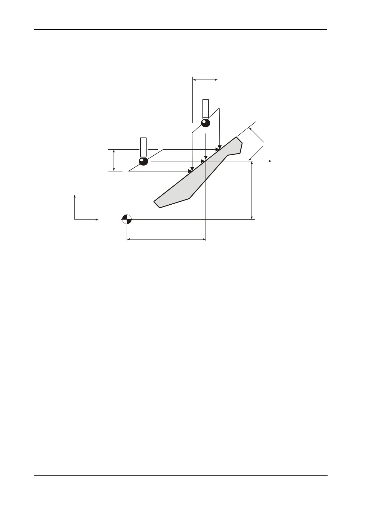
Figure 9.20 Measuring an angled surface in the X or Y plane
Description
This cycle measures an X axis or Y axis surface at two positions to establish the angular
position of the surface.
Application
The probe stylus must be positioned adjacent to the surface and at the required Z axis
position to provide a suitable start position. The cycle makes two measurements,
symmetrically about the start position, to establish the surface angle.
Format
G65 P9843 Xx Dd [Aa Bb Qq Ww]
or
G65 P9843 Yy Dd [Aa Bb Qq Ww]
where [ ] denote optional inputs
Example: G65 P9843 X50. D30. A45. H.2 Q15. W1.
Publication No. H-2000-6222
Additional cycles
9-39
Compulsory inputs
Dd
d = The distance moved parallel to the X axis or Y axis between the two
measuring positions.
Xx
x = The mid-point surface position of the surface. An Xx input results in a
cycle measuring in the X axis direction.
Yy
y = The mid-point surface position of the surface. A Yy input results in a cycle
measuring in the Y axis direction.
NOTE: Do not mix the Xx and Yy inputs.
Optional inputs
Aa
a = The nominal angle of the surface measured from the X+ axis direction
positive angles (counter-clockwise). Specify angles between ±90 degrees
of the default value.
Defaults:
X axis measuring 90 degrees.
Y axis measuring 0 degrees.
Bb
b = The angle tolerance of the surface, e.g., 30 degrees ±1 degrees. Inputs
A30.B1.
Qq
q = The probe move overtravel distance. Default value is 10 mm (0.394 in).
Ww w = Print data
1.
= Increment the feature number only.
2.
= Increment the component number, and reset the feature number.
Outputs
#189
The surface angle measured from the X+ direction.
#193
The measured height difference.
#194
The surface angle error.
Alarms
Refer to Chapter 10, “Macro alarm list” for details of the macro alarms.
Publication No. H-2000-6222
9-40
Additional cycles
Example
30.0
Y+
O
45
X+
Y30.0
X30.0
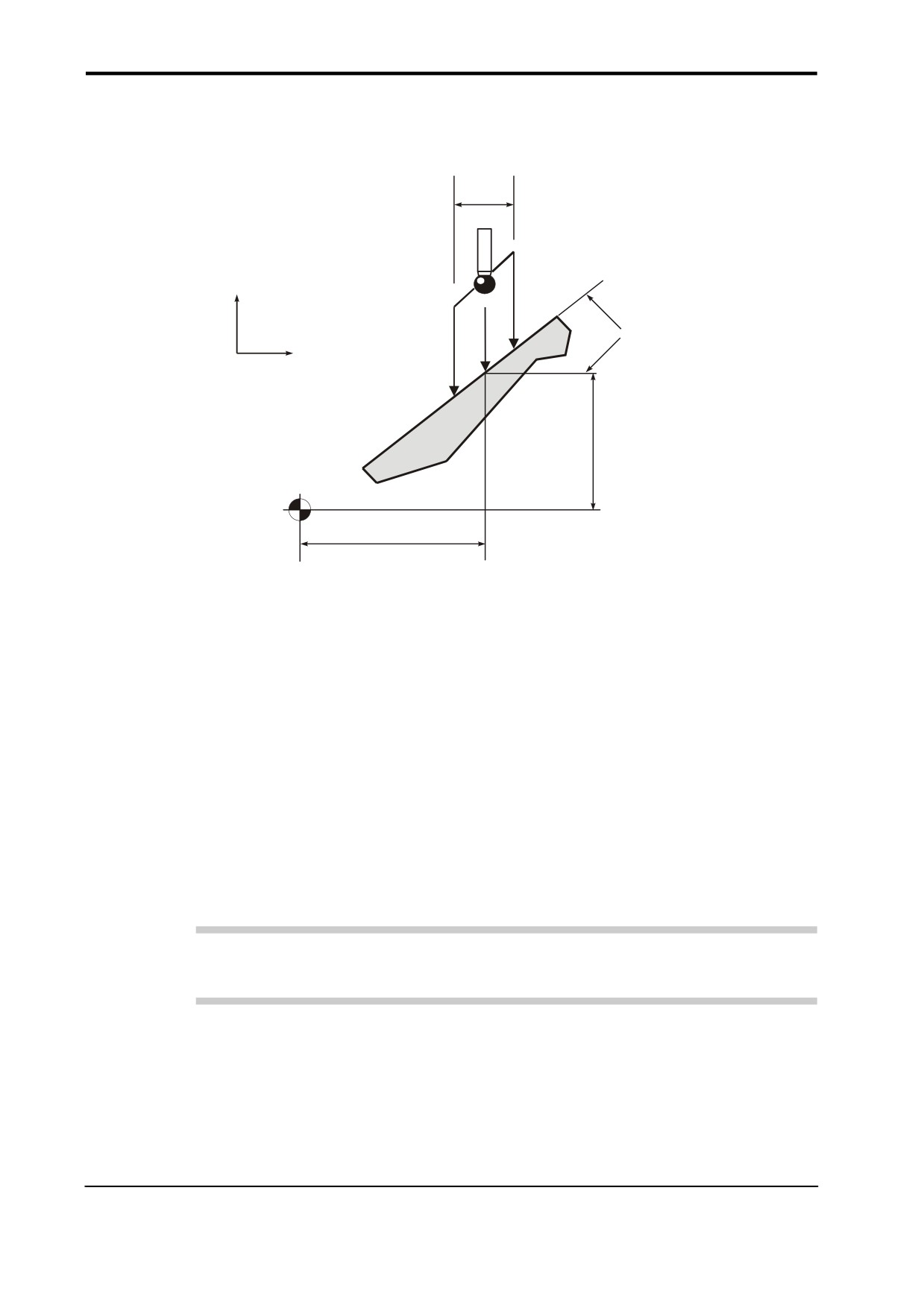
Figure 9.21 Example of an angled surface measurement
G65P9810 X30.Y50.Z100.F3000
Protected positioning move.
G65P9810 Z-15.
Protected move to start position.
G65P9843Y30.D30.A45.
Angle measure.
G65P9810 Z100.
Retract to a safe position.
continue
G17
G68G90X0Y0 R[#189]
Rotate co-ordinate system by the angle.
Continue machining program
NOTE: The Renishaw probe cycles cannot be used while co-ordinate rotation is in force,
i.e. cancel code G69.
Publication No. H-2000-6222
Macro alarms
10-1
Chapter 10
Macro alarms
When an error occurs during use of the Inspection Plus software, an alarm number or
message is generated. This will be displayed on the screen of the controller.
Contained in this chapter
General alarms
10-2
Optimisation macro only (O9836) alarms
10-5
Publication No. H-2000-6222
10-2
Macro alarms
General alarms
Format
#198 flag
3006 =
1(OUT OF TOL)
Updates the offset if
1
1(OUT OF POS)
the cycle start button is
2
1(ANGLE OUT OF TOL)
pressed to continue.
4
1(DIA OFFSET TOO LARGE)
5
1(UPPER TOL EXCEEDED)
No offset update if the
3
1(EXCESS STOCK)
cycle start button is
6
pressed to continue.
1(PROBE SWITCH OFF FAILURE) Turn-off macro O9833
Action
Check the following:
The turn-off cycle may fail if the spindle speed of S500 is not achieved. Check
that the spindle speed override is not active.
Possible faulty probe.
Cycle start to continue.
Format
#3000 = 101(PROBE START UP FAILURE)
Turn-on macro O9832
Action
Check the following:
The turn-on cycle may fail if the spindle speed of S500 is not achieved. Check
that the spindle speed override is not active.
Possible faulty probe.
This is a reset condition. Edit the program and start again from a safe start position.
Publication No. H-2000-6222
Macro alarms
10-3
Format
#3000 =
91
(MESSAGE)
91
(FORMAT ERROR)
91
(A
INPUT MISSING)
91
(B
INPUT MISSING)
91
(C
INPUT MISSING)
91
(D
INPUT MISSING)
91
(I
INPUT MISSING)
91
(J
INPUT MISSING)
91
(K
INPUT MISSING)
91
(X
INPUT MISSING)
91
(Y
INPUT MISSING)
91
(Z
INPUT MISSING)
91
(XYZ
INPUT MISSING)
91
(DATA
#180 TO #189 MISSING)
91
(X0
INPUT NOT ALLOWED)
91
(Y0
INPUT NOT ALLOWED)
91
(H
INPUT NOT ALLOWED)
91
(T
INPUT NOT ALLOWED)
91
(IJK
INPUTS 5 MAX)
91
(XY
INPUT MIXED)
91
(XY
INPUT MIXED)
91
(ZK
INPUT MIXED)
91
(SH
INPUT MIXED)
91
(ST
INPUT MIXED)
91
(TM
INPUT MIXED)
91
(XYZ
INPUT MIXED)
91
(K
INPUT OUT OF RANGE)
Action
Edit the program.
This is a reset condition. Edit the program and start again from a safe start position.
Publication No. H-2000-6222
10-4
Macro alarms
Format
#3000 = 86(PATH OBSTRUCTED) protected positioning cycle only.
Action
Edit the program.
This is a reset condition. Clear the obstruction and start again from a safe position.
Format
#3000 = 88(NO FEED RATE) protected positioning cycle only
Action
Edit the program.
This is a reset condition. Insert the F___ code input, and start again from a safe position.
Format
#3000 = 89(NO TOOL LENGTH ACTIVE)
Action
Edit the program.
This is a reset condition. G43 or G44 must be active before the cycle is called. Edit and
start again from a safe position.
Format
#3000 = 92(PROBE OPEN) This alarm occurs if the probe is already triggered before a
move.
Action
Clear the fault.
This is a reset condition. Clear the fault and start again from a safe start position. The
stylus may be in contact with a surface, or the probe has failed to reseat. This could be
due to swarf trapped around the probe eyelid.
Publication No. H-2000-6222
Macro alarms
10-5
Format
#3000 = 93(PROBE FAIL) This alarm occurs if the probe did not trigger during the move.
Action
Edit the program.
This is a reset condition. Edit the program and start again from a safe start position. The
surface was not found or the probe has failed.
Optimisation macro only (O9836) alarms
Format
#3000 = 72(SKIP SIGNAL ALREADY ACTIVE) optimisation macro only.
This indicates that the machine skip signal is high prior to the probe move.
Action
Check that the probe is active and that the interface is not in error. Check wiring. Check
that the interface output relay is configured correctly, i.e. N/C or N/O. Is the stylus in
contact with a surface? Is there a possible reseat problem?
Clear the fault.
Format
#3000 = 73(NO SKIP SIGNAL DURING MOVE) optimisation macro only.
The skip signal was not activated during the move.
Action
Check the wiring. Check the probe's operation and interface LED outputs to confirm when
the stylus is manually deflected; also relay output voltage to skip when the probe is
triggered.
Edit the program.
Publication No. H-2000-6222
10-6
Macro alarms
Format
#3000 = 74(H00 CODE TOOL LENGTH NOT ACTIVE) optimisation macro only.
The tool length offset must be set to zero by programming ‘H00’ prior to calling the macro.
This permits the safe operation of jogging the stylus into a start position before running the
macro.
Action
Edit the program.
Format
#3000 = 75(#168=BMCF DIST AND #169=FAST FEED) optimisation macro only.
This is the end of the optimisation cycle. The values in #168 and #169 can be installed
(see “Optimising a probing cycle - macro O9836” in Chapter 9, “Additional cycles” for
details).
Action
Install setting values.
Publication No. H-2000-6222
Example job
A-1
Appendix A
Example job
Contained in this appendix
Introduction
A-2
Probe operations
A-3
Publication No. H-2000-6222
A-2
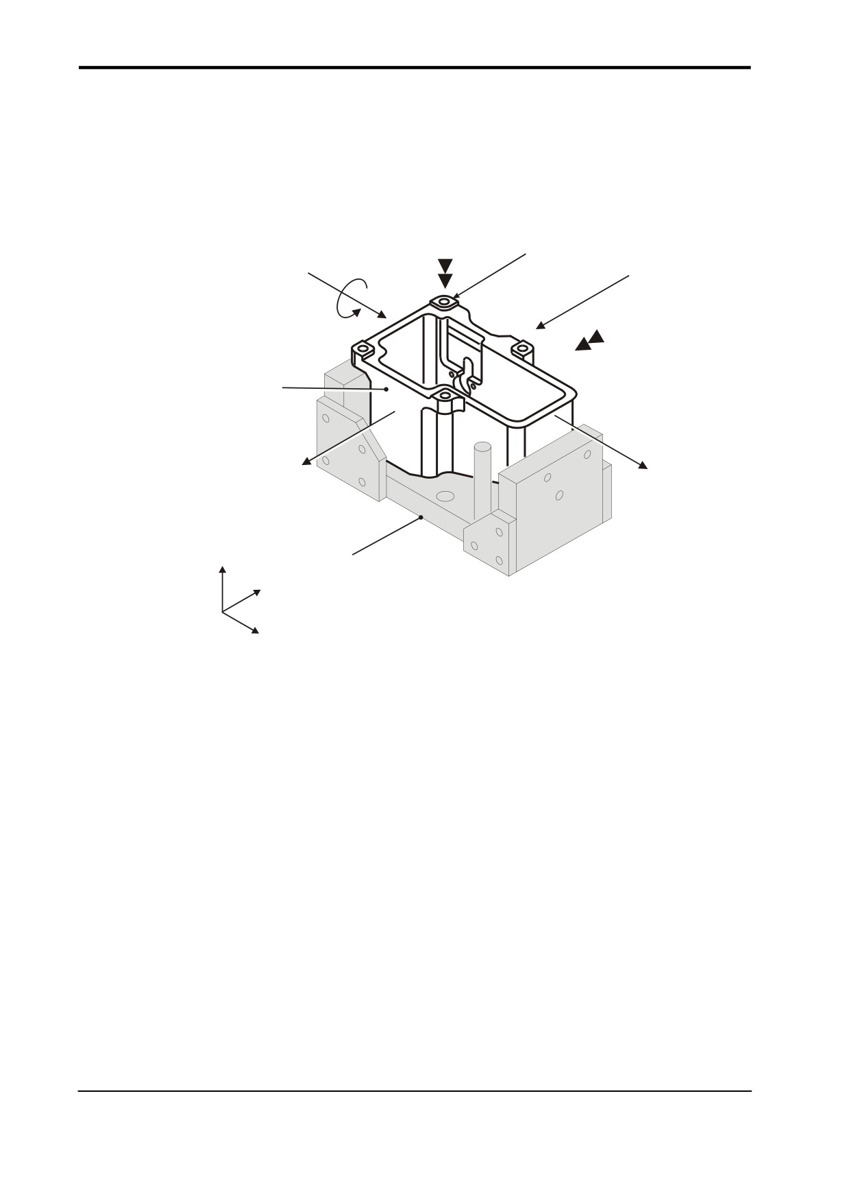
Example job
Introduction
The component shown in Figure A.1 is to be machined on two faces by rotating the
component about the machine A axis on the 4th axis unit.
Machined
o
0
lower left
face
pad
X+
Y+
'A' axis
270o
face
Motorised
arm base
Z
Fixture
Y
X
Figure A.1 Motorised arm base - general view
The following probe operations are carried out:
z
The probe is used initially on the 0 degree face to level up the component using an
A axis work offset shift.
z
The component datum is then set in the X, Y, and Z axis for machining.
During machining of this face, the side face of the lower left pad is machined as a
datum for the 270 degree face machining (Ref. Y axis datum).
z
The probe is also used on the 270 degree face to set the Y, Z axis component
datum.
Nominal work offset data is entered in G54 and G55 before the machining operation.
Publication No. H-2000-6222
Example job
A-3
Probe operations
%
O5866
(M-2116-0031-01-D)
(MOTORISED ARM-BASE)
(TAPE NO - T5866)
(*)
(PROBE TO FIND CENTRE)
G17G94
G90G40G80
N10M00
(COMPONENT SET UP PROBING)
(LOAD NOMINAL WORK OFFSETS)
/T30
Select the probe
/G91G28Z0A0
Retract
/G28A0
Position A axis
/G90
Absolute co-ordinates
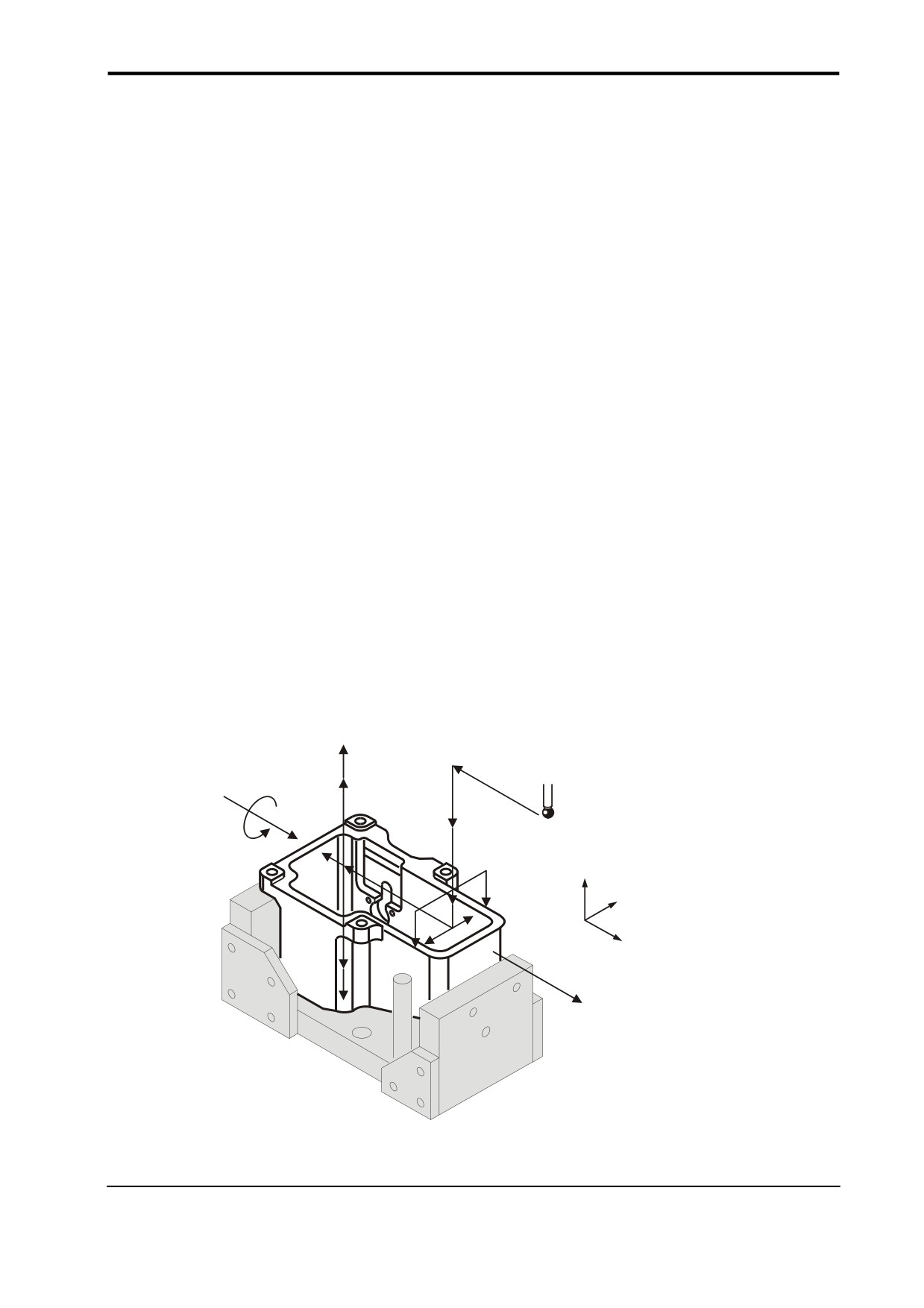
Refer to Figure A.2 for probe movements 1 to 18
18
NOTE
17
1
6
2
The machine Z axis is initially
'A'
16
aligned with the 0° face.
3
4
11
Z
10
Y
5
8
9
X
14
15
X+
Figure A.2 Probing operations on the 0-degree face
Publication No. H-2000-6222
A-4
Example job
1.
/G00G54X90.Y0.
Rapid positioning
2.
/G43G1H30Z100.F3000
Go to Z 100 mm (3.94 in), apply tool offset.
3.
/G65P9832
Switch the probe on.
4.
/G65P9810Z10.F3000
Protected move to start position.
5.
/G65P9818Y79.Z0S1.
Set G54 A axis on the top face.
6.
/G0A0
Level to new A axis position.
7.
/#5244=#5224
Transfer G54 A axis to G55 A axis work offset.
8.
/G65P9810Z-28.F3000.
Protected move to position.
9.
/G65P9812Y69.S1.
Set G54 Y centre.
10.
/G65P9810X-35.Y0
Protected move to position.
11.
/G65P9811X-44.S1.
Set G54 X position.
12.
/#5241=#5221
Transfer G54 X axis to G55 X axis work offset.
13.
/G65P9810X0
Protected move to position.
14.
/G65P9810Z-84.
Protected move to position.
15.
/G65P9811Z-94.S1.
Set G54 Z position.
16.
/G65P9810Z100.
Protected move retract.
17.
/G65P9833
Switch the probe off.
18.
/G91G28Z0
/G90
/M01
Continue machining 0-degree face
G0A-90.
Index to 270 degree face.
N210
(PROBE TO SET G55 Y Z)
/M01
/T30
Select probe.
/M09
/G91G28Z0
/G90
Publication No. H-2000-6222
Example job
A-5
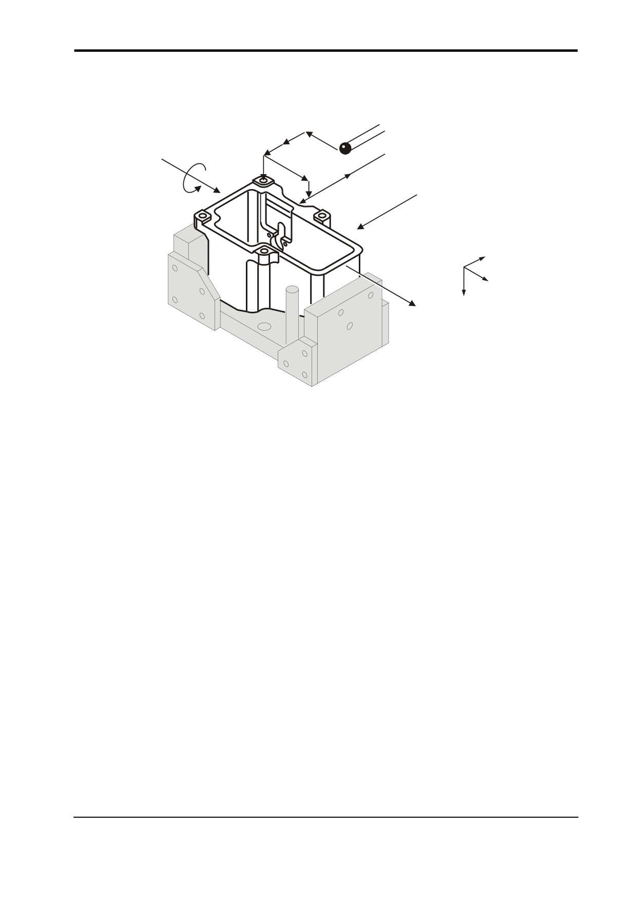
Refer to Figure A.3 for probe movements 20 to 30
21
NOTE
22
20
The machine Z axis is now
23
aligned with the 270° face.
25
30
24
'A'
29
270o
26
28
face
27
Z
X
Y
X+
Figure A.3 Probing operations on the 270-degree face
20.
/G0G55X-38.0Y-74.0
Rapid positioning move
21.
/G43G1H30Z100.F3000
Go to Z 100 mm (3.94 in), apply tool offset.
22.
/G65P9832
Switch the probe on.
23.
/G65P9810Z-5.F3000.
Protected move to position.
24.
/G65P9811Y-66.S2.
Set G55 Y axis work offset.
25.
/G65P9810X0Z10.
Protected move to position.
26.
/G65P9810Y-60.
Protected moves to position.
27.
/G65P9811Z0S2.
Set G55 Z axis work offset.
28.
/G65P9810Z100.
Protected move retract.
29.
/G65P9833
Switch the probe off.
30.
/G91G28Z0
Retract
/G90
/M01
Publication No. H-2000-6222
A-6
Example job
Continue machining 270-degree face
G91G28Z0
Z return
G28X0Y0A0
X, Y, A return to start position.
G90
N420
M01
M30
%
Publication No. H-2000-6222
Features, cycles and limitation
B-1
Appendix B
Features, cycles and limitations of the
Inspection Plus software
Contained in this appendix
Features of the Inspection Plus software
B-2
Cycles
B-3
Limitations
B-3
Limitations when using vector cycles O9821, O9822 and O9823
B-3
Use of 3-point bore/boss macro O9823
B-4
Mathematical precision
B-4
Effect of vector calibration data on results
B-4
Publication No. H-2000-6222
B-2
Features, cycles and limitations of the Inspection Plus software
Features of the Inspection Plus software
z
Protected positioning.
z
Measurement of internal and external features to determine both size and position.
This includes:
z
Obtaining a hardcopy printout of feature data.
z
Applying tolerances to both size and position.
z
Additional features for feedback of errors include:
z
Experience values can be applied to the measured size.
z
Percentage feedback of the error can be applied.
z
Null band zone for no-tool offset update.
z
SPC (statistical process control) feedback based on average value.
z
Calculation of feature-to-feature data.
z
Measurement of external and internal corners for corner surfaces which may not be
parallel to an axis.
z
Calibration of multiple stylii.
z
4th axis datum setting and tolerancing.
z
Angular measurement of features.
z
Software option to turn off the tolerance alarms and provide a flag-only alarm.
Suitable for FMS and unmanned applications.
z
Built in protection for stylus collision and false trigger protection for all cycles.
z
Diagnostic and format error checking routines for all cycles.
Publication No. H-2000-6222
Features, cycles and limitation
B-3
Cycles
z
Protected positioning.
z
Measurement:
z
XYZ single surface.
z
Web / pocket.
z
Bore / boss (four measuring points).
z
Internal and external corner find.
z
Vectored measurement:
z
3-point bore boss.
z
Web / pocket.
z
Single surface.
z
Additional macros:
z
4th axis measurement.
z
Bore / boss on a PCD.
z
Stock allowance.
z
Multi-stylus calibration.
z
XY plane angle measurement.
Limitations
z
The probe cycles will not run if ‘mirror image’ is active.
z
The probe cycles will not run if ‘co-ordinate rotation’ is active.
z
Consider macro variable availability.
Limitations when using vector cycles O9821, O9822 and O9823
Vectored cycles involve the mathematical operation of squared values. This can lead to
precision errors if large values are used. The following factors must be considered:
Publication No. H-2000-6222
B-4
Features, cycles and limitations of the Inspection Plus software
Use of 3-point bore/boss macro O9823
The macro may be used to establish the centre and diameter of a bore or external feature.
There is however a practical limitation to the use of the macro. It is advisable to use the
largest distance between contacts, that is practical. The minimum conditions to give
reliable data are as follows:
z
1.
168 degrees total span.
2.
48 degrees between any two points.
z
The software does not check the minimum condition inputs.
z
The accuracy of the result deteriorates if the minimum conditions are not followed.
Mathematical precision
The mathematical precision of the controller is a limiting factor if large values are used.
The controller works within an accuracy of eight significant figures. Because of the
mathematical operations concerned, an error may accumulate if large values for probing
positions about the centre are used for calculation. It is suggested that, at this moment, X
Y coordinate values of ±300.00 mm (30.000 in) from the feature centre are not exceeded
for any position around a bore, to retain a resultant resolution of better than 0.01 mm
(0.001 in).
Effect of vector calibration data on results
The vector calibration cycle establishes true calibration data at each 30 degree increment.
A small error due to the probe's trigger characteristics may occur at intermediate angles
between the 30 degree calibration points. However this error is small for standard
machine tool probes with standard styli.
NOTE: For better accuracy, always use the standard bore boss cycle (O9814) where
possible.
Publication No. H-2000-6222
Settings macro details
C-1
Appendix C
Settings macro details
Contained in this appendix
Macro G65P9724
C-2
Publication No. H-2000-6222

C-2
Settings macro details
Macro G65P9724
This macro is called at the beginning of all top level macros to establish the necessary
modal information.
The following data may be adjusted to suit during the installation by editing this macro.
The following values are supplied as standard:
#170 = 1 (SELECT OPTIONS)
(see the table below)
#173 = .05 (POSITION ZONE MM) This is the zone at either the start or end of the block
in which the cycle is aborted with either Probe Open
or Probe Fail.
#169 = 5000 (FAST FEED MM)
The fast feed rate of the cycles can be
#169 = 200 (FAST FEED INCH)
adjusted by this variable to suit the machine
characteristics and should be optimised.
NOTES:
1.
The X, Y and Z axis P9726 basic move macro fast feedrate is #169*.6, i.e.
3 metres/min as standard.
2.
All Z axis positioning moves are also #169*.6, i.e. 3 metres/min as standard.
3.
All XY axis positioning moves are #169 value i.e. 5 metres/min as standard.
Setting conditions for variable #170
Radius/diameter tool offset type
Tolerance alarm method
Setting value
Radius type
Flag and alarms
#170=3
Diameter type
Flag and alarms
#170=19
Radius type
Flag only
#170=7
Diameter type
Flag only
#170=23
It is expected that the settings to enable ‘Flag only alarms’ will suit FMS machining cells
where the requirement is to run unmanned. The process error flag #198 will be set and it
should be monitored after relevant probe cycles for corrective action.
Publication No. H-2000-6222
Settings macro details
C-3
Example
G65 P9812 X30.H.2
Set tolerance on measured size
IF[#198EQ1] GOTO999
Test for out of tolerance
continue part program
GOTO1000
N999 G65P5001
Pallet change. This changes the pallet to select the
next component for machining (details are machine
dependent).
GOTO1
Go to start of program
N1000
M30
Publication No. H-2000-6222
C-4
Settings macro details
This page intentionally left blank.
Publication No. H-2000-6222
Tolerances
D-1
Appendix D
Tolerances
Contained in this appendix
Tolerances
D-2
True position tolerances
D-3
Publication No. H-2000-6222
D-2
Tolerances
Tolerances
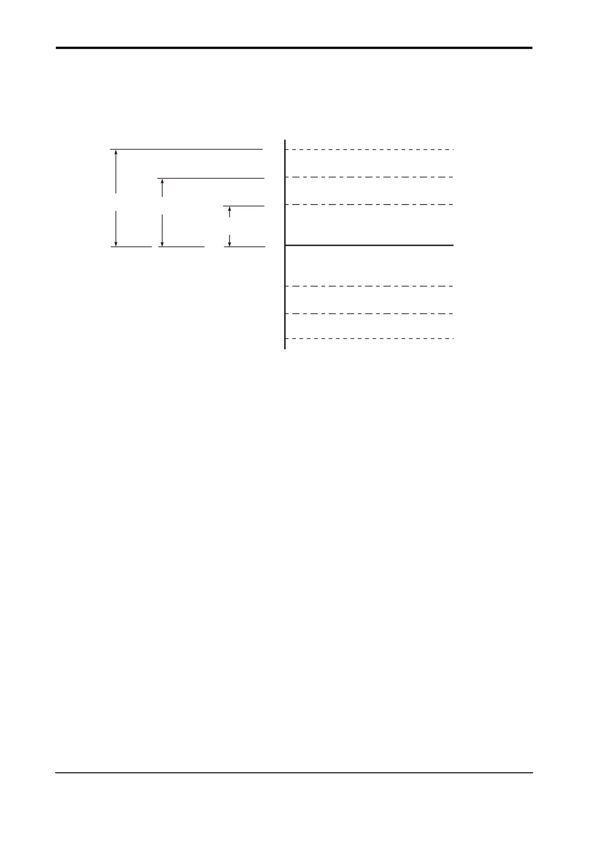
Uu, Hh and Vv apply to size and tool offset updates only.
e
+
d
c
Uu
Hh tol
Vv input
b
a
_
a
= Nominal size
b
= Null band. This is the tolerance zone where no tool offset adjustment occurs.
c
= Area where the Ff input is effective in percentage feedback. F (0 to 1) gives 0% to
100% feedback to the tool offset.
d
= Hh “Out of Tolerance alarm” occurs. The tolerance value is that which is applied
to the size of a feature.
e
= Uu upper tolerance limit. If this value is exceeded there is no tool offset or work
offset updated and the cycle is stopped with an alarm. This tolerance applies to
both size and position where applicable.
Figure D.1 Size and tool offset update tolerances
Also see SPC macro O9835 (see Chapter 9, “Additional cycles”) which can be used as a
modified method for the feedback of tool offset corrections. Use this instead of Ff.
Publication No. H-2000-6222