Inspection Plus software for Haas machining centres. Programming manual (H-2000-6222-0A-B) - page 4
Additional cycles
9-3
Compulsory inputs
Xx
x = The X axis distance between Z1 and Z2 measurement positions.
Zz
z = The Z axis expected surface position.
Optional inputs
Bb
b = Set a tolerance on the angular position of the feature. It is equal to half the
total tolerances, e.g. component dimension 45 degrees (±0.25 degrees)
the 4th axis would be positioned to 45 degrees and B.25 tolerance.
Qq
q = The probe's overtravel distance for use when the default values are
unsuitable. The probe then travels beyond the expected position when it
searches for a surface. Default values are 10 mm (0.4 in).
Ss
s = The work offset number which will be set.
The work offset number will be updated.
S1 to S6 (G54 to G59)
S0 (external work offset).
S110 to S129 (G110 to G129) additional offsets option.
S154.01 to S154.99 (G154 P1 to G154 P99) additional offsets option.
New work offset = active work offset + error.
New external offset = external offset + error.
Ww w = Print data
1.
= Increment the feature number only.
2.
= Increment the component number, and reset the feature number.
Outputs
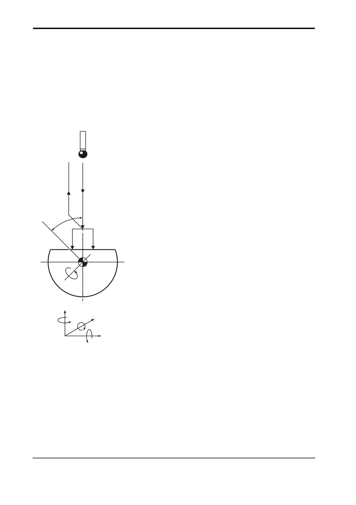
#193 will show (Z1 - Z2) value
#194 will show angle correction value
#189 will show 4th axis measured position
NOTE: Different machines and application may require the 4th axis system variable
number to be changed. It will be achieved by editing macro O9817 when the macro is
installed to suit your machine.
Edit as follows:
#3 = 4 (4th axis number) change axis number as required.
Publication No. H-2000-6222
9-4
Additional cycles
Axis direction change
Edit as follows:
#4 = 1 (1 = clockwise, and -1 = counter-clockwise) change as required.
Example
Set the 4th axis to a milled flat
1.
T01M06
Select the probe.
9
1
2.
G43H1Z200.
Activate offset 1, go to 100 mm
(3.94 in).
2
3.
G65P9832
Spin the probe on (includes
8
3
M19), or M19 for spindle
orientation.
7
5
O
BO
45
4.
G0B45.
Position 4th axis to 45 degrees.
6
5.
G65P9810X0Y0Z20.F3000
Position 10 mm (0.394 in) above
the surface.
6.
G65P9817X50.Z10.B5.
Measure at 50 mm (1.9685 in)
centres, update G54 and set a
4
tolerance of 5 degrees.
7.
G65P9810Z200.
Protected positioning move.
8.
G65P99833
Spin the probe off (when
Z
applicable).
C
B
Y
9.
G28Z200.
Reference return.
A
X
continue
Figure 9.2
Probe movements
Publication No. H-2000-6222
Additional cycles
9-5
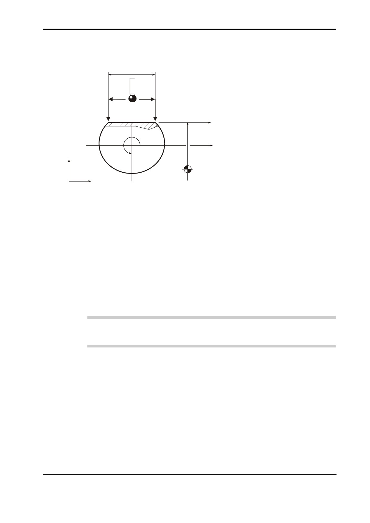
4th axis Y measurement - macro O9818
Yy
NOTE:
Angle correction to 4th axis
+ (positive) counter-clockwise
- (negative) clockwise
Y0 (BO)
Z+
Zz
Y+
Figure 9.3 4th axis Y measurement
Description
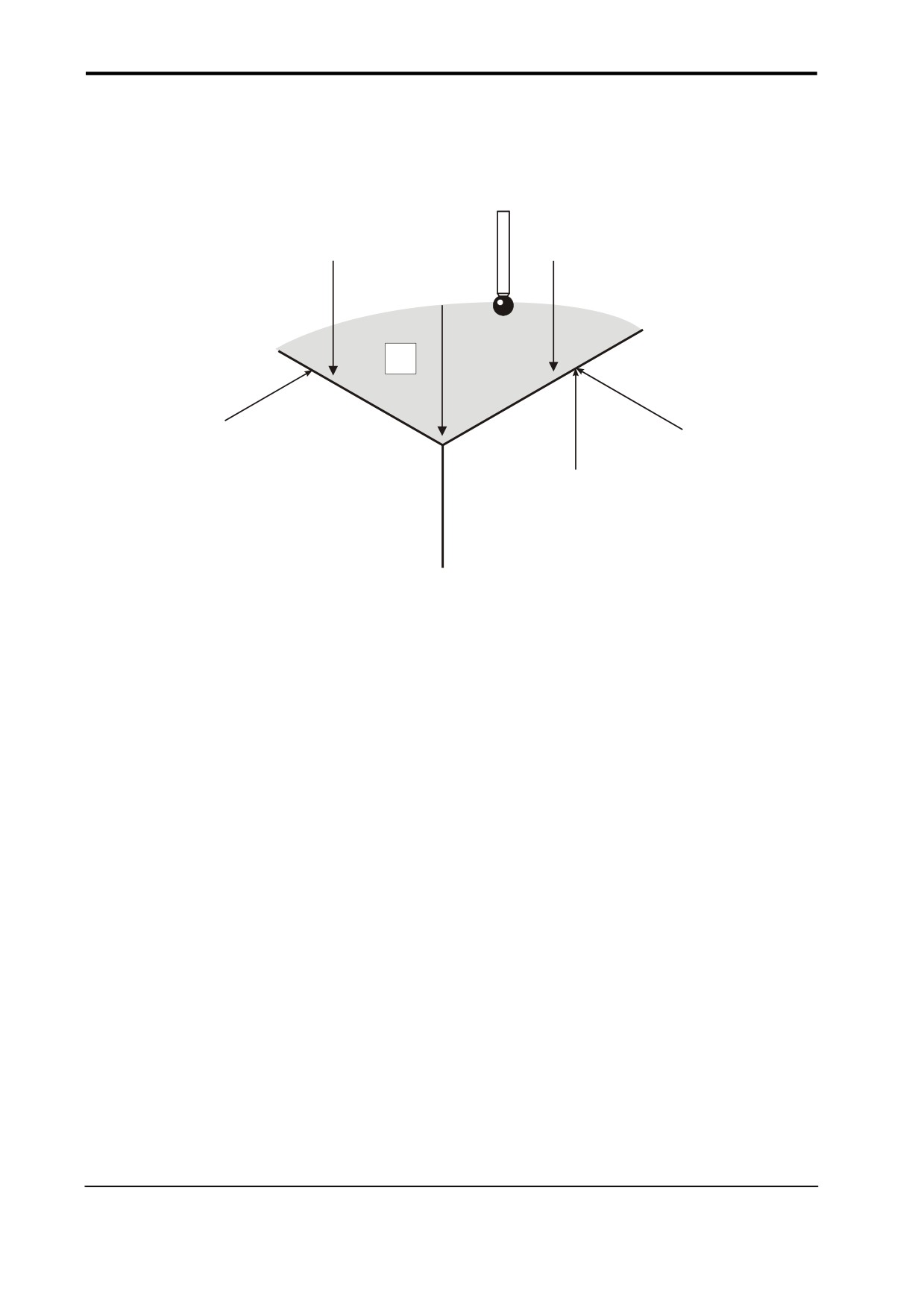
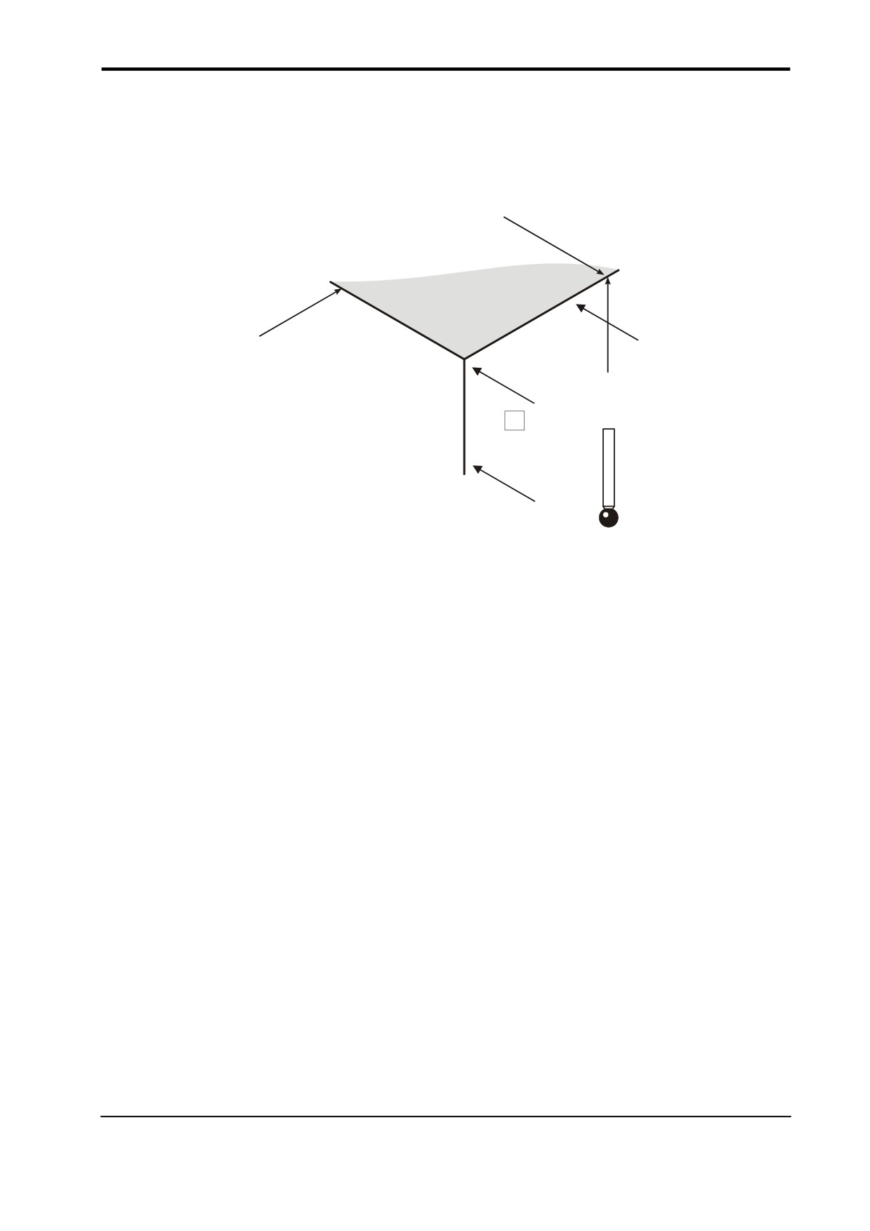
The purpose of this macro is to find the slope of a surface between two points Z1 and Z2
and make the necessary correction by indexing a ‘rotary axis’ to compensate. It also
updates a ‘work zero point’ for that axis if required.
Application
The 4th axis must be positioned to the expected angular position of the feature, i.e.
surface normal to the Z axis. The cycle finds the error of surface position, and then adjusts
the axis work offset or checks a tolerance.
NOTE: It is normally necessary on most machines to re-state the work offset and move to
the angular position after the cycle to make the new work offset active.
Format
G65 P9818 Yy Zz [Qq Bb Ss Ww]
where [ ] denote optional inputs
Example: G65 P9818 Y100. Z50. Q10. B2. S1. W2.
Publication No. H-2000-6222
9-6
Additional cycles
Compulsory inputs
Yy
y = The Y axis distance between Z1 and Z2 measurement positions.
Zz
z = The Z axis expected surface position.
Optional inputs
Bb
b = Set a tolerance on the angular position of the feature. It is equal to half the
total tolerances, e.g. component dimension 45 degrees ±.25 degrees the
4th axis would be positioned to 45 degrees and B.25 tolerance.
Qq
q = The probe's overtravel distance for use when the default values are
unsuitable. The probe then travels beyond the expected position when it
searches for a surface. Default values are 10 mm (0.4 in).
Ss
s = The work offset number which will be set.
The work offset number will be updated.
S1 to S6 (G54 to G59)
S0 (external work offset).
S110 to S129 (G110 to G129) additional offsets option.
S154.01 to S154.99 (G154 P1 to G154 P99) additional offsets option.
New work offset = active work offset + error.
New external offset = External offset + error.
Ww w = Print data
1.
= Increment the feature number only.
2.
= Increment the component number, and reset the feature number.
Outputs
#193 will show (Z1 - Z2) value
#194 will show angle correction value
#189 will show 4th axis measured position
NOTE: Different machines and application may require the 4th axis system variable
number to be changed. It is achieved by editing macro O9818 when the macro is installed
to suit your machine.
Edit as follows:
#3 = 4 (4th axis number) change axis number as required.
Publication No. H-2000-6222
Additional cycles
9-7
Axis direction change
Edit as follows:
#4 = 1 (1 = clockwise, and -1 = counter-clockwise) change as required.
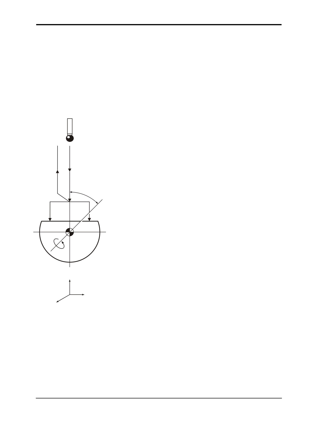
Example
Set the 4th axis to a milled flat
1.
T01M06
Select the probe.
2.
G43H1Z200.
Activate offset 1, go to 100 mm
(3.94 in).
9
1
3.
G65P9832
Spin the probe on (includes M19), or
2
M19 for spindle orientation.
3
4.
G0A45.
Position 4th axis to 45 degrees.
8
5.
G65P9810X0Y0Z20.F3000
Position 10 mm (0.394 in) above the
7
O
5
45
surface.
6
AO
6.
G65P9818Y50.Z10.S1.B5.
Measure at 50 mm (1.9685 in) centres,
update G54 and set a tolerance of 5
degrees.
7.
G65P9810Z200.
Protected positioning move.
4
8.
G65P9833
Spin the probe off (when applicable).
9.
G28Z200.
Reference return.
Continue
Z
Y
X
Figure 9.4
Probe movements
Publication No. H-2000-6222
9-8
Additional cycles
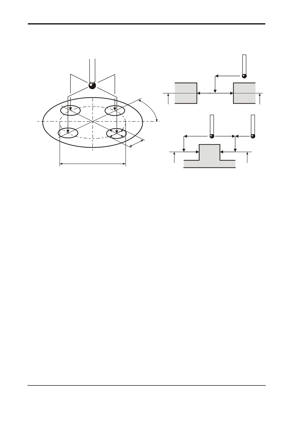
Bore / boss on PCD measurement - macro O9819
NOTE:
Angles in the range ±180°
+Aa angles (counter-clockwise)
o
90
Aa
Kk
Kk
o
o
180
0
Dd
o
-90
Zz
Zz
Cc P.C.D.
Figure 9.5 Bore / boss on PCD measurement
Description
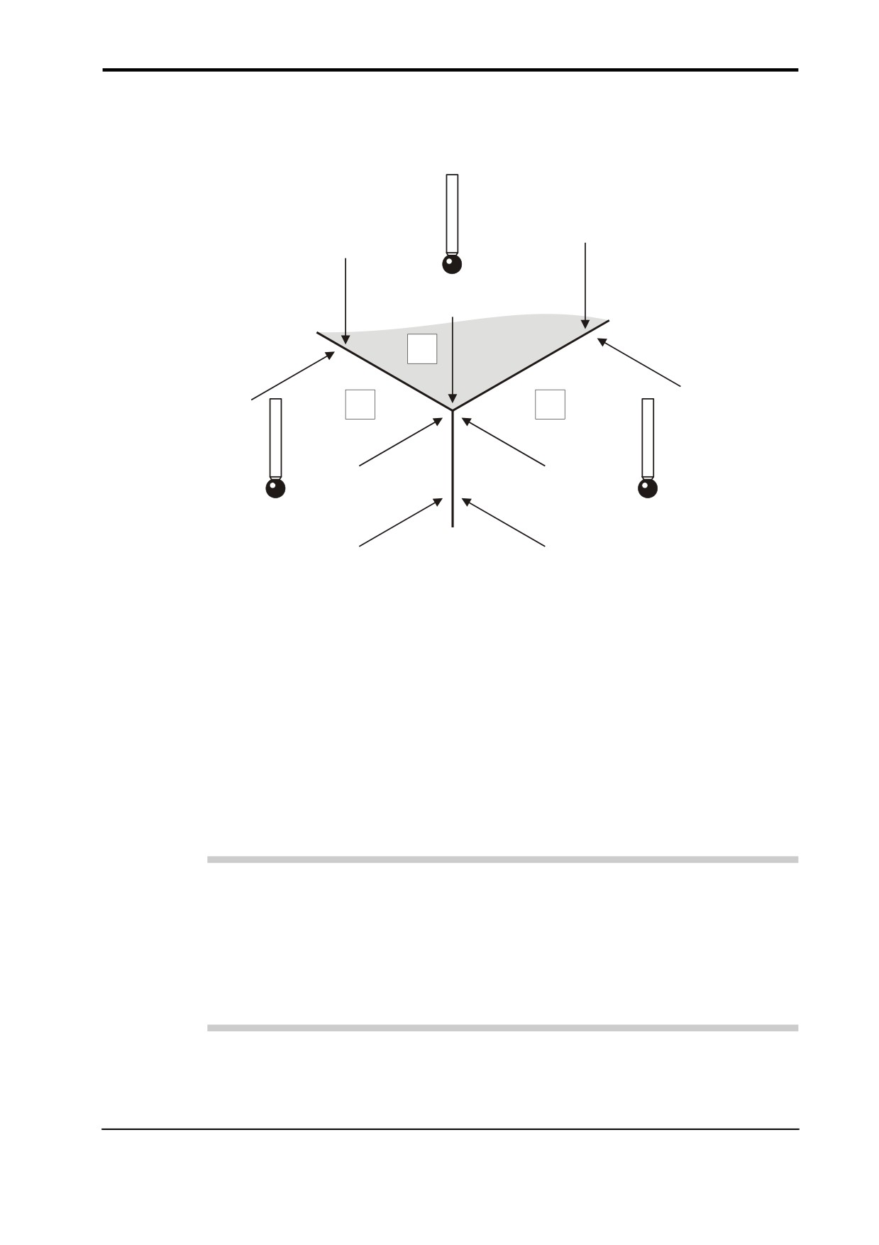
The macro measures a series of bores or bosses on a pitch circle diameter (PCD). All
probe moves occur automatically and return to the start position at the centre of the PCD.
Application
1.
The probe is positioned at the centre of the PCD above the component. The probe
moves to all bore/boss features and measures each feature automatically. The
probe then returns to the PCD centre at the end of the cycle.
2.
The macro makes use of the bore/boss macro which is nested within the moves.
This means that the macro nesting level is four deep, which means that this macro
cannot be nested inside a customer macro.
3.
If a “probe open” condition occurs during any of the moves between bore/boss
features a path obstructed alarm occurs and the probe stays in position instead of
returning to the start position as is usual. This is done for safety reasons because
the return path to centre line of the PCD may be obstructed.
Publication No. H-2000-6222
Additional cycles
9-9
Format
Boss G65 P9819 Cc Dd Zz [Aa Bb Ee Hh Mm Qq Rr Uu Ww]
or
Bore G65 P9819 Cc Dd Kk [Aa Bb Ee Hh Mm Qq Rr Uu Ww]
where [ ] denote optional inputs.
Example: G65 P9819 C28.003 D50.005 K11. A45.005 B2. E0.005 H0.2 M0.2 Q10. R10.
U.5 W2.
Compulsory inputs
Cc
c = PCD. The pitch circle diameter of the bore/boss feature.
Dd
d = Diameter of the bore/boss.
Kk
k = Absolute Z axis position where the bore is to be measured.
Zz
z = Absolute Z axis position where the boss is to be measured.
Optional inputs
Aa
a = Angle measured from the X axis to the first bore/boss feature. Default
value = 0.
Bb
b = The number of bore/boss features on the PCD. Default value = 1.
Hh
h = The tolerance value of the bore/ boss dimension being measured.
Mm m = The true position tolerance of the bore or boss. A cylindrical zone about
the theoretical position.
Qq
q = The probe's overtravel distance for use when the default values are
unsuitable. The probe then travels beyond the expected position when it
searches for a surface. Default values are 4 mm (0.16 in) in the Z axis
and 10 mm (0.394 in) in the X,Y axis.
Rr
r =
This is an incremental dimension that is used in an external bore or boss
to give a radial clearance from the nominal target surface prior to a Z axis
move. Default value is 5 mm (0.200 in).
R-r
-r = This is an incremental dimension that is used in an internal boss or web to
give a radial clearance from the nominal target surface prior to a Z axis
move. Default value is 5 mm (0.200 in).
Publication No. H-2000-6222
9-10
Additional cycles
Ww w = Print data
1.
= Increment the feature number only.
2.
= Increment the component number, and reset the feature number.
For optional inputs Ee and Uu, see Chapter 3, “Optional inputs”.
Outputs
The feature measurements will be stored in variables #185 to #199 (see Chapter 4,
“Variable outputs”).
W2.0 Component number (incremented by 1). Feature number (set to 1).
W1. Feature number (incremented by 1).
The following data is output to the ‘on-line device’ (printer):
Diameter of each bore/boss
1.
XY absolute position of each feature. Angle position of each feature. PCD pitch circle
diameter of each feature.
2
The feature number.
3.
Error of size and position.
Refer to the print macro details for the output format.
Uu
u = When the upper tolerance is exceeded. The macro continues to the end
of the macro and print data is output for each feature. The “Upper
Tolerance Exceeded” alarm occurs and #169 = 2 is set if #170 is set.
Otherwise the flag #169 = 2 is set only. The program continues.
Publication No. H-2000-6222
Additional cycles
9-11
Stock allowance - macro O9820
P2
P(6 max)
P1
Z
P(6 max)
P(6 max)
X
Y
P1
P1
P2
P2
Figure 9.6 Measuring the stock allowance
Description
The cycle measures either an X or Y or Z surface at defined positions to establish the
maximum and minimum stock condition of the surface.
Application
The probe should be positioned above the surface at the first measuring position. The
cycle measures the surface at this position (P1). Additional points P2 to P6 maximum are
measured as defined, depending on the number of sets of I, J, or K inputs.
NOTES:
1.
If setting a work offset, the surface position will be at the minimum measured position
and the stock value is seen in #196.
2.
If NOT setting a work offset the nominal position is assumed and the maximum and
minimum values are seen in #194 and #195.
Publication No. H-2000-6222
9-12
Additional cycles
Format
X surface measure
NOTE: Successive pairs of Jj, Kk values
G65 P9820 Xx Jj Kk [Ss Uu]
must be in order for P2 to P6.
or
Y surface measure
NOTE: Successive pairs of Ii, Kk values
G65 P9820 Yy Ii Kk [Ss Uu]
must be in order for P2 to P6.
or
Z surface measure
NOTE: Successive pairs of Ii, Jj values
G65 P9820 Zz Ii Jj [Ss Uu]
must be in order for P2 to P6.
where [ ] denote optional inputs
Example: G65 P9820 X100. J10. K11. S1. U.5
(this shows one additional [JK] pair of values, i.e. P2)
Compulsory inputs
Xx
or
Yy
x, y, z =
The nominal surface position for stock allowance check.
or
Zz
I1 (P2) to I5 (P6)
i = X surface positions for P2 to P6 (maximum five additional
positions).
or
J1 (P2) to J5 (P6) j = Y surface positions for P2 to P6 (maximum five additional
positions).
or
K1 (P2) to K5 (P6) k = Z surface positions for P2 to P6 (maximum five additional
positions).
Publication No. H-2000-6222
Additional cycles
9-13
Optional inputs
Uu
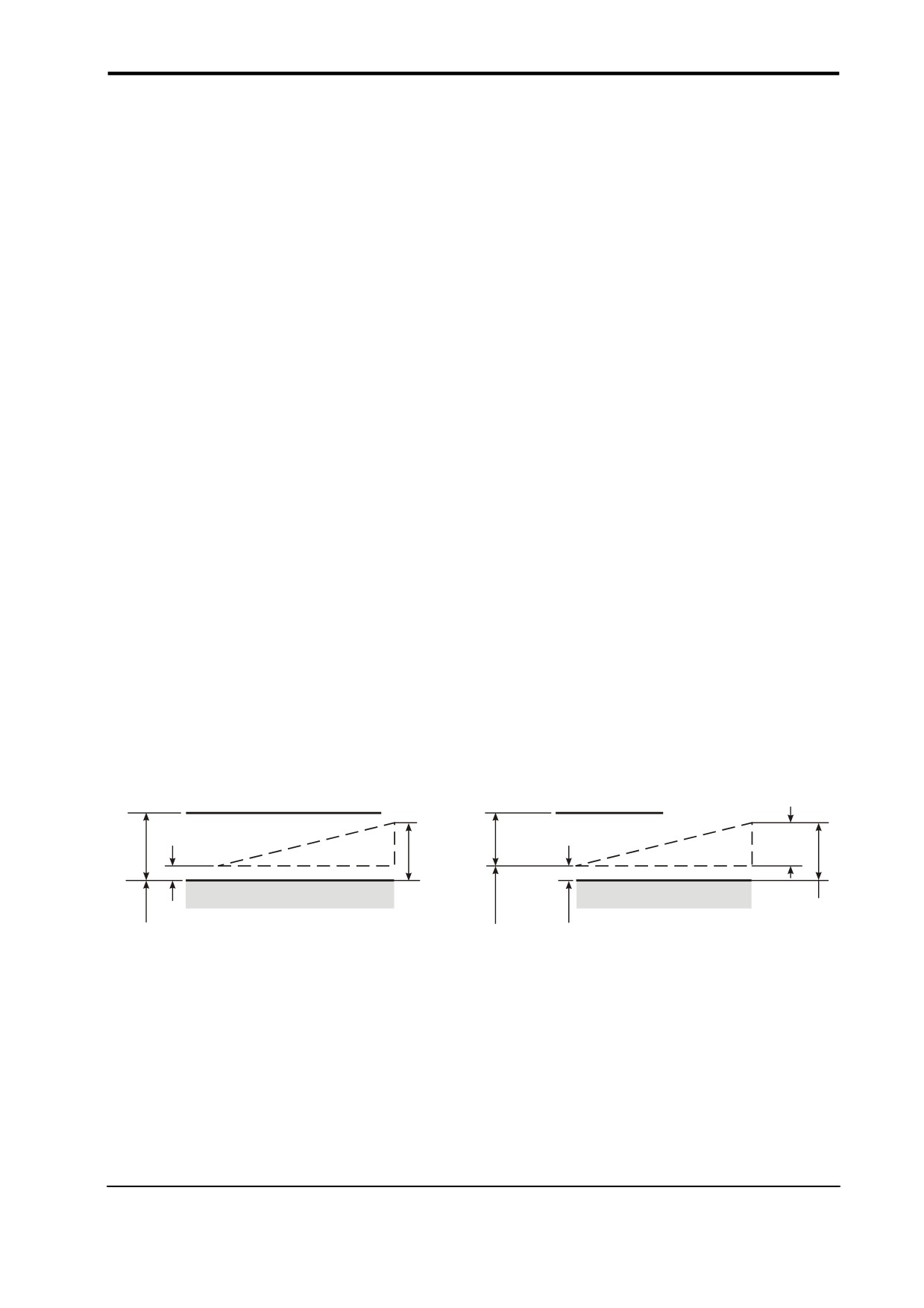
u = The maximum stock allowance or upper tolerance (metal condition).
1.
Uu input only. The upper tolerance metal condition, e.g., surface at
30.00 +2.0/-0.0
G65P9820Z30.0U2.0IiJj
2.
Uu and Ss input. The maximum stock allowance.
Ss
s = The work offset number which will be set. This will be set to the minimum
metal position #195.
The work offset number will be updated.
S1 to S6 (G54 to G59)
S0 (external work offset).
S110 to S129 (G110 to G129) additional offsets option.
S154.01 to S154.99 (G154 P1 to G154 P99) additional offsets option.
New work offset = active work offset + error.
New external offset = external offset + error.
Outputs
1.
Uu input only
“Upper tolerance exceeded” flag #198 will be set to 3
2.
Uu and Ss input
“Excess stock” flag #198 will be set to 6
#194
Maximum value (metal condition)
#195
Minimum value (metal condition)
#196
Variation (stock allowance)
Uu INPUT ONLY
Uu AND Ss INPUT
Upper tolerance exceeded
Excess stock
#195
Uu
#195
Uu
#196
#194
#194
Nominal
Work
Nominal
position
offset set
position
to this
position
Figure 9.7 Outputs for the stock allowance cycle
Publication No. H-2000-6222
9-14
Additional cycles
Example 1
Checking a Z surface for stock variation
P3
P2
P1
Z
X50.0
Y50.0
Z0
P1 at X55 Y55
P2 at X155 Y55
P3 at X55 Y155
Figure 9.8 Checking a Z surface for stock variation
Select the probe.
G65P9810X55.Y55.Z20.F3000
Protected move to P1.
G65P9820Z0I155.J55.I55.J155.U2.
Measure at P1, P2, P3 and set a 2 mm
(0.039 in) tolerance.
continue machining
Publication No. H-2000-6222
Additional cycles
9-15
Example 2
Checking an X surface and updating a work offset
X20.0
Y50.0
P2
Z50.0
P1
X
P1 at Y55. Z45.
P2 at Y105. Z45.
P3
P3 at Y180. Z45.
Figure 9.9 Checking an X surface and updating a work offset
Select the probe.
G65P9810X40.Y55.Z45.F3000
Protected move to P1.
G65P9820 X20.J105.K45.J180. K45.S2 Measure at P1, P2, P3 and set the X axis
work offset G55 to the minimum stock position
at program position X20. Retract, select tool
and offset G55 for machining X surface at the
new X20. surface position.
Publication No. H-2000-6222
9-16
Additional cycles
Storing multi-stylus data - macro O9830
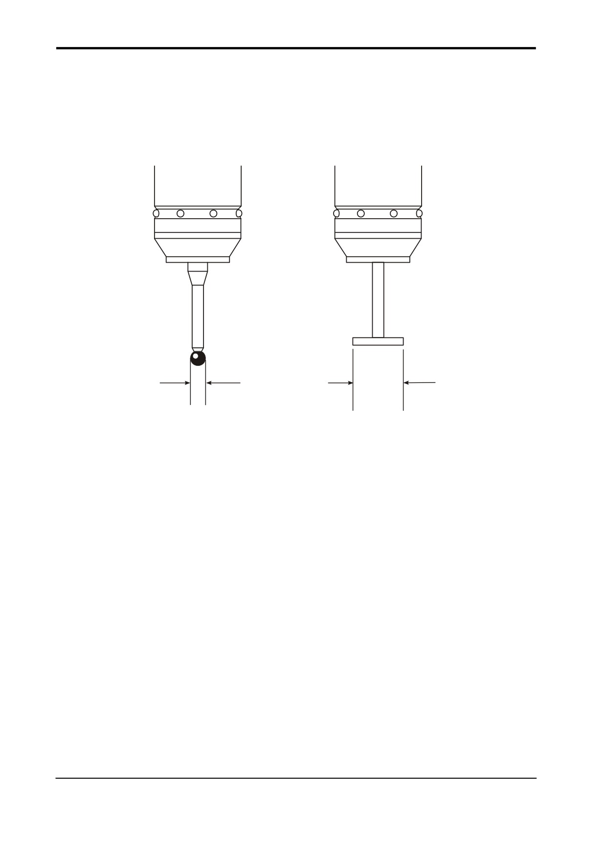
This cycle stores the data following calibration.
Probe 1
Probe 2
K2
K1
Calibration data
Calibration data
Figure 9.10 Storing multi-stylus data
Description
The macro is used to store probe stylus calibration data that has been established during
the calibration cycles. It is stored in a spare set of macro variables. This macro must be
used in conjunction with macro O9831 to recall relevant calibration data for each probe.
Application
Calibrate the stylus using macro O9802 and O9803. Run macro O9830 to store the
calibration data #556 (556+0) to #559 (556+3). The values are recalled when macro
O9831 is run.
It is also possible to store calibration data for vector cycles, by the use of the optional
input.
Format
G65 P9830 Kk
Example: G65 P9830 K11.
Publication No. H-2000-6222
Additional cycles
9-17
Compulsory input
Kk
k = The multi-stylus probe number for data storage.
Active calibration data
Store location
XRAD YRAD XOFF YOFF
XRAD YRAD XOFF YOFF
K1
#556
#557
#558
#559
#574
#575
#576
#577
K2
#556
#557
#558
#559
#578
#579
#580
#581
For vector calibration data storage
#556 to #559 are stored as shown above, plus all the vector radii as shown below.
Buffer calibration data
Store location
RAD RAD RAD RAD
K11
#566
#567
#568
#569
#582
#583
#584
#585
#570
#571
#572
#573
#586
#587
#588
#589
K12
#566
#567
#568
#569
#590
#591
#592
#593
#570
#571
#572
#573
#594
#595
#596
#597
Publication No. H-2000-6222
9-18
Additional cycles
Example
Multi-stylus store K1
O0003
G90G80G40G0
Preparatory codes for the machine.
G54X0Y0
Start position (X, Y, Z values must be set in the work offset)
G43H1Z100.
Activate offset 1, go to 100 mm (3.94 in).
G65P9832
Spin the probe on (includes M19), or M19 for spindle orientation.
G65P9810Z-5.F3000
Protected positioning move for Z.
G65P9803D50.001
Calibrate in a reference feature (ring gauge).
G65P9830K1
Store calibration values for multi-stylus K1.
G65P9810Z100.
Protected positioning move.
G65P9833
Spin the probe off (when applicable)
G28Z100.
Reference return.
H00
Cancel offset.
M30
End of program
Publication No. H-2000-6222
Additional cycles
9-19
Loading multi-stylus data - macro O9831
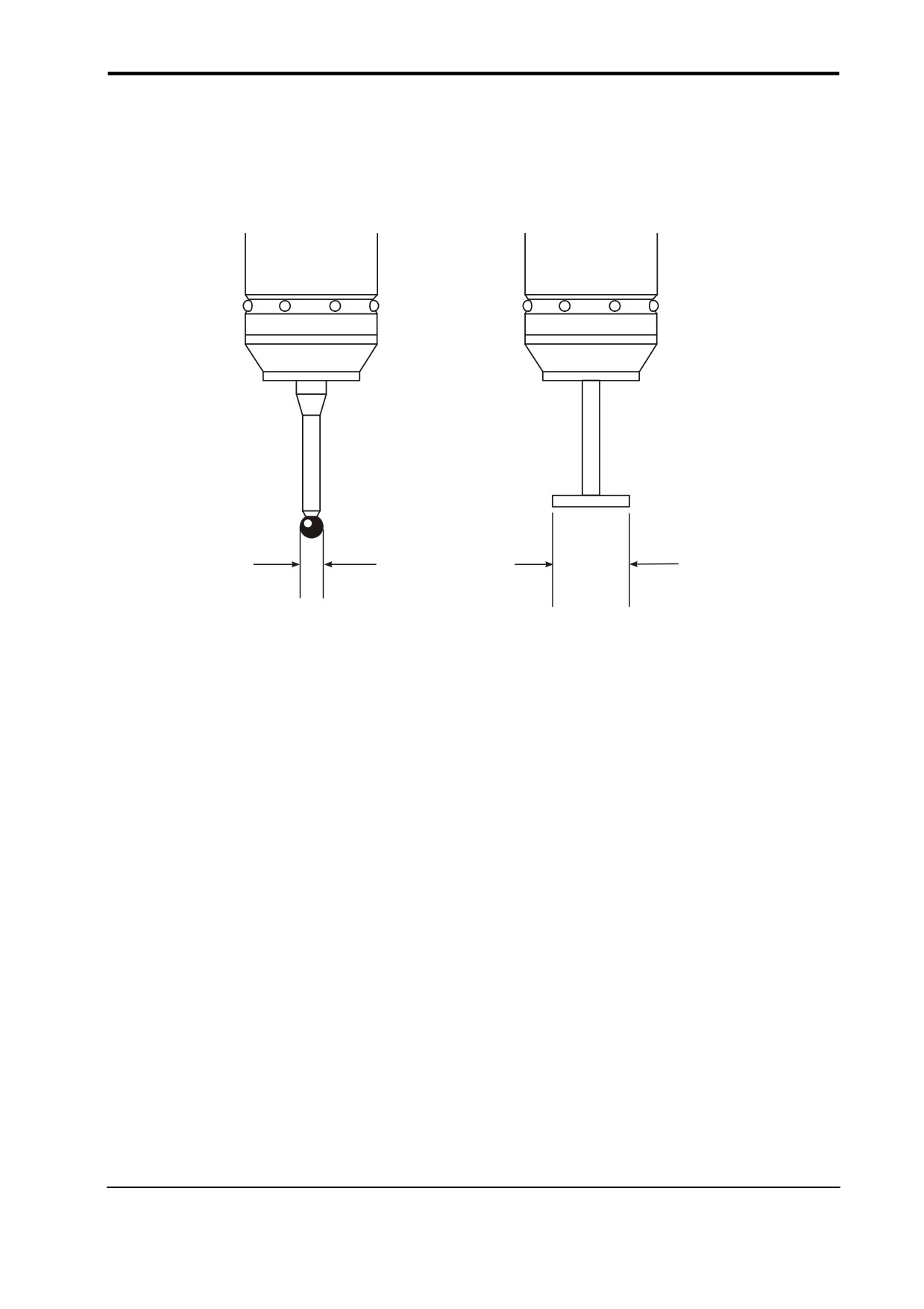
This cycle recalls the calibration data.
Probe 1
Probe 2
K2
K1
Calibration data
Calibration data
Figure 9.11 Recalling multi-stylus data
Description
This macro is used in conjunction with O9830. It is used to recall stored calibration data
to the active calibration variable range prior to using a particular probe stylus
configuration.
Application
The program must be run immediately before any measuring cycle to select the correct
probe calibration data. The Kk input determines the data to be recalled.
Format
G65 P9831 Kk
Example: G65 P9831 K11.
Publication No. H-2000-6222
9-20
Additional cycles
Compulsory input
Kk
k = The multi-stylus probe number for data recall. The Kk input number
should always be the same as that used to store the data using O9830 for
a given stylus.
Active calibration data
Store location
XRAD YRAD XOFF YOFF
XRAD YRAD XOFF YOFF
K1
#556
#557
#558
#559
#574
#575
#576
#577
K2
#556
#557
#558
#559
#578
#579
#580
#581
For vector calibration data storage
#556 to #559 are stored as shown above, plus all the vector radii as shown below.
Buffer calibration data
Store location
RAD RAD RAD RAD
K11
#566
#567
#568
#569
#582
#583
#584
#585
#570
#571
#572
#573
#586
#587
#588
#589
K12
#566
#567
#568
#569
#590
#591
#592
#593
#570
#571
#572
#573
#594
#595
#596
#597
Publication No. H-2000-6222
Additional cycles
9-21
Example
Multi-stylus load K1 and K2
T01M06
Select the probe.
G54X100.Y100.
Start position.
G43H1Z100.
Activate offset 1, go to 100 mm (3.94 in).
G65P9832
Turn the probe on (includes M19), or M19 for spindle
orientation.
G65P9810Z-10.F3000
Protected positioning move.
G65P9831K1
Load calibration values for multi-stylus K1.
G65P9814D30.S2
Measure a 30.0 mm (1.181 in) diameter bore.
G65P9810Z10.
Protected positioning move.
G65P9810X350.
Protected positioning move.
G43H2Z-10.
Activate offset 2.
G65P9831K2
Load calibration values for multi-stylus K2.
G65P9814D130.S2
Measure a 130.0 mm (5.12 in) diameter bore.
G65P9810Z100.
Protected positioning move.
G65P9833
Turn the probe off (when applicable).
G28Z100.
Reference return.
continue
Publication No. H-2000-6222
9-22
Additional cycles
Turning the probe on - macro O9832
Description
This macro is used to turn the probe on prior to it being used. The probe is loaded into the
spindle and moved to a safe start plane, where the above format is used to activate the
probe.
In the event of a start-up failure, there is a loop in the software which tries to activate the
probe up to four times. An alarm results if the probe does not activate.
It should be noted that a small automatic Z axis movement takes place within the macro to
test if the probe is active.
NOTE: The probe tool offset must be active.
Format
G65P9832
Example
G43H20Z100.
Apply a tool offset and move to a safe plane.
G65P9832
Turn the probe on (includes M19), or M19 for spindle
orientation.
G65P9810X----Y----F----
Move to a gauging position.
Publication No. H-2000-6222
Additional cycles
9-23
Turning the probe off - macro O9833
Description
This macro is used to turn the probe off prior to it being used. The probe is retracted to a
safe start plane, where the above format is used to switch the probe off prior to a tool
change.
There is a loop in the software, which will tries to de-activate the probe up to four times.
An alarm results if the probe does not switch off.
It should be noted that a small automatic Z axis movement takes place within the macro to
test if the probe is active. This means that the G28 reference return must be done
following this macro, otherwise the G28 position is not effective.
NOTE: The probe tool offset must be active.
Format
G65P9833
Example
G65P9810Z100.
Retract to a safe plane with the tool offset still active.
G65P9833
Turn the probe off.
G91
G28Z0
Retract
continue
Publication No. H-2000-6222
9-24
Additional cycles
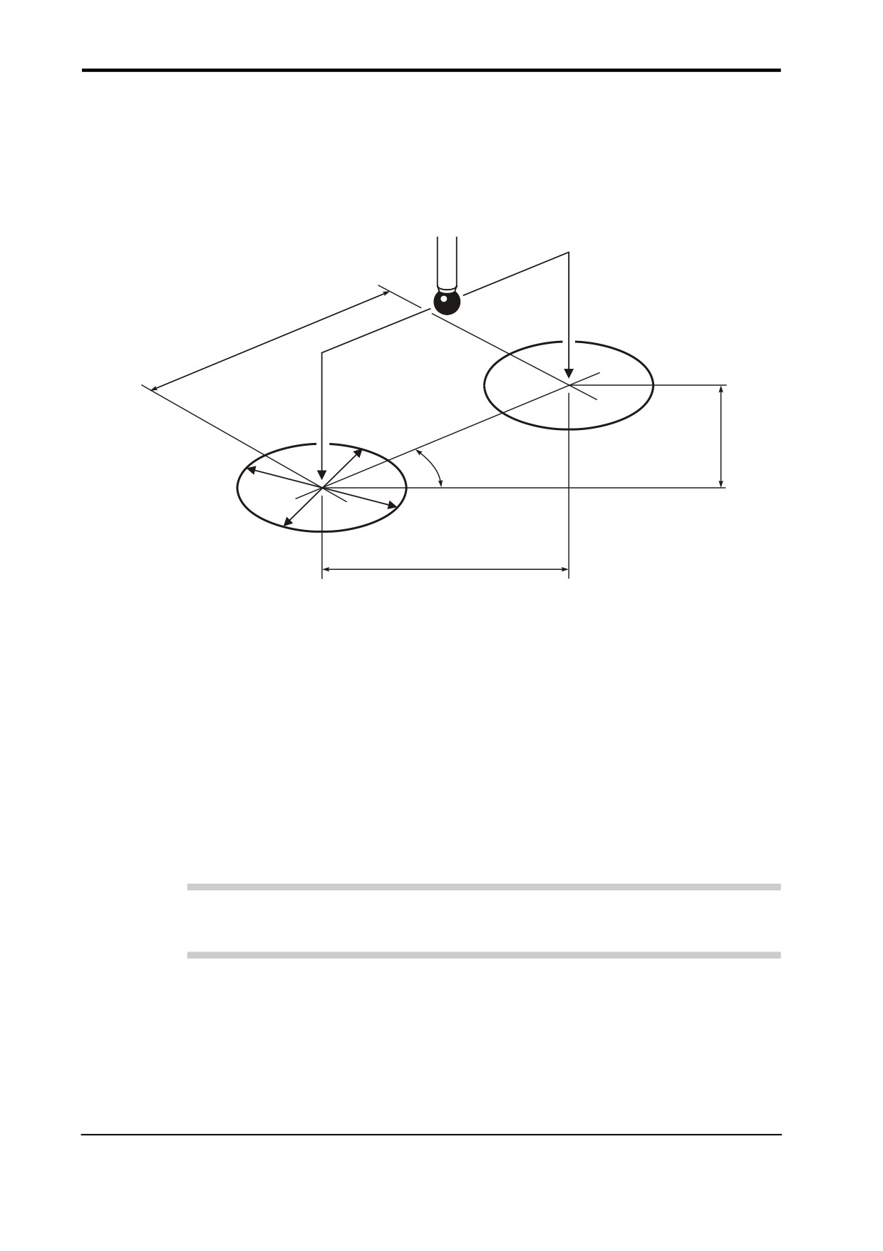
Determining feature-to-feature data in the XY plane - macro
O9834
NOTE:
Angles in the range ±180°
+Aa angles (counter-clockwise)
Dd
P2
Yy
Aa
P1
Xx
Figure 9.12 Determining feature-to-feature data in the XY plane
Description
This is a no-movement macro that is used after two measuring cycles to determine
feature-to-feature data.
Application
Data for P1 and P2 must already be stored in variables #180 to #184, and #185 to #197
for P2, by running suitable measuring cycles.
NOTE: The order P1 and P2 is important, because the data calculated is that of P2 with
respect to P1.
Values for P1 are obtained by programming G65 P9834 without any inputs after the first
measuring cycle.
Values for P2 are obtained by running a second measuring cycle - the feature-to-feature
data is established by programming G65 P9834 with suitable inputs after the second
measuring cycle.
Publication No. H-2000-6222
Additional cycles
9-25
Format
G65 P9834 Xx [Ee Ff Hh Mm Ss Tt Uu Vv Ww]
or
G65 P9834 Yy [Ee Ff Hh Mm Ss Tt Uu Vv Ww]
or
G65 P9834 Xx Yy [Bb Ee Hh Mm Ss Uu Ww]
or
G65 P9834 Aa Dd [Bb Ee Hh Mm Ss Uu Ww]
or
G65 P9834 (with no inputs).
where [ ] denote optional inputs
Examples
G65 P9834 X100. E0.005 F0.8 H0.2 M0.2 S1.T20. U.5 V.5 W2.
or
G65 P9834 Y100. E0.005 F0.8 H0.2 M0.2 S1. T20. U.5 V.5 W2.
or
G65 P9834 X100. Y100. B2. E0.005 H0.2 M0.2 S1. U.5 W2.
or
G65 P9834 A45.005 D50.005 B2. E0.005 H0.2 M0.2 S1. U.5 W2.
NOTES:
1.
Updating a tool offset with T input is only possible if either O9811 or O9821 is used
for P2 data. Otherwise an alarm (T INPUT NOT ALLOWED) results.
2.
This cycle cannot be used in conjunction with the web/pocket cycle macro O9812.
3.
Angles. The XY plane is with respect to the X+ axis direction. Use angles in the
range ±180 degrees.
4.
When G65P9834 (without any inputs) is used, then the following data is stored:
from
#185
to
#180
#186
#181
#187
#182
#188
#183
#189
#184
Publication No. H-2000-6222
9-26
Additional cycles
Compulsory inputs
Xx
x = The nominal incremental distance in the X axis.
Yy
y = The nominal incremental distance in the Y axis.
Aa
a = The angle of P2 with respect to P1 measured from the X+ axis (angles
between ±180 degrees).
Dd
d = The minimum distance between P1 and P2.
(No inputs)
This is used to store output data of the last cycle for P1 data.
Optional inputs
Bb
b = The angle tolerance of the surface, e.g. 30 degrees ±1 degree.
Hh
h = The tolerance value of the feature dimension being measured.
Mm m = The true position tolerance of a feature. A cylindrical zone about the
theoretical position.
Ss
s = The work offset number which will be set.
The work offset number will be updated.
S1 to S6 (G54 to G59)
S0 (external work offset).
S110 to S129 (G110 to G129) additional offsets option.
S154.01 to S154.99 (G154 P1 to G154 P99) additional offsets option.
New work offset = active work offset + error.
New external offset = external offset + error.
Tt
t =
The tool offset number to be updated.
Ww w = Print data
1.
= Increment the feature number only.
2.
= Increment the component number, and reset the feature number.
For optional inputs Ee, Ff, Uu and Vv, see Chapter 3, “Optional inputs”.
Publication No. H-2000-6222
Additional cycles
9-27
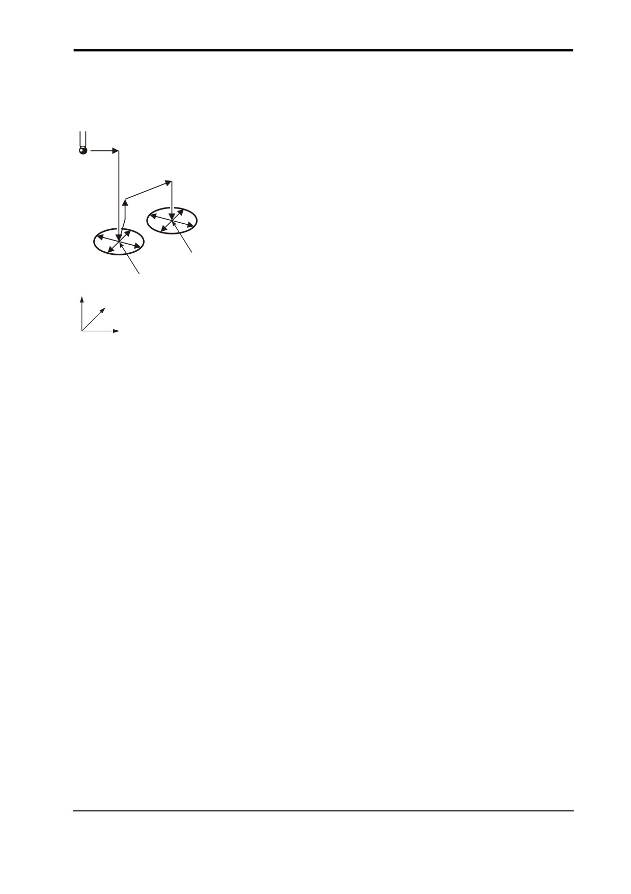
Example 1
Measuring the incremental distance between two holes
1
2
1.
G65P9810X30.Y50.F3000 Protected positioning move.
3
7
8
2.
G65P9810Z-10.
Protected positioning move.
6
3.
G65P9814D20.
P1 20 mm (0.787 in) bore.
9 and 10
4.
G65P9834
Store data.
4 and 5
5.
G65P9810Z10.
Protected positioning move.
Z
Y
6.
G65P9810X80.Y78.867
Move to new position.
X
7.
G65P9810Z-10.
Protected positioning move.
Figure 9.13
Probe movements
8.
G65P9814D30.
P2 30 mm (1.181 in) bore.
And either this
9.
G65P9834X50.Y28.867M.1 Incremental distance measure with
0.1 mm (0.0039 in) true position
tolerance.
Or this
9.
G65P9834A30.D57.735M.1
Publication No. H-2000-6222
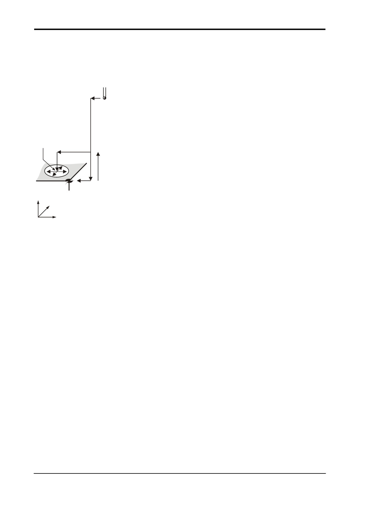
9-28
Additional cycles
Example 2
Surface to bore measurement
1
1.
G65P9810X10.Y50.F3000 Protected positioning move.
2.
G65P9810Z-10.
Protected positioning move.
2
3.
G65P9811X0.
P1 at X 0 mm (0 in) position.
4.
G65P9834
Store data.
8 and 9
6
5.
G65P9810Z10.
Protected positioning move.
7
6.
G65P9810X-50.
Move to new position.
5
7.
G65P9810Z-10.
Protected positioning move.
3 and 4
8.
G65P9814D20.5
P2 20.5 mm (0.807 in) bore.
Z
Y
9.
G65P9834X-50.H.2
Measure distance 50 mm (-1.97 in).
X
Figure 9.14
Probe movements
Publication No. H-2000-6222
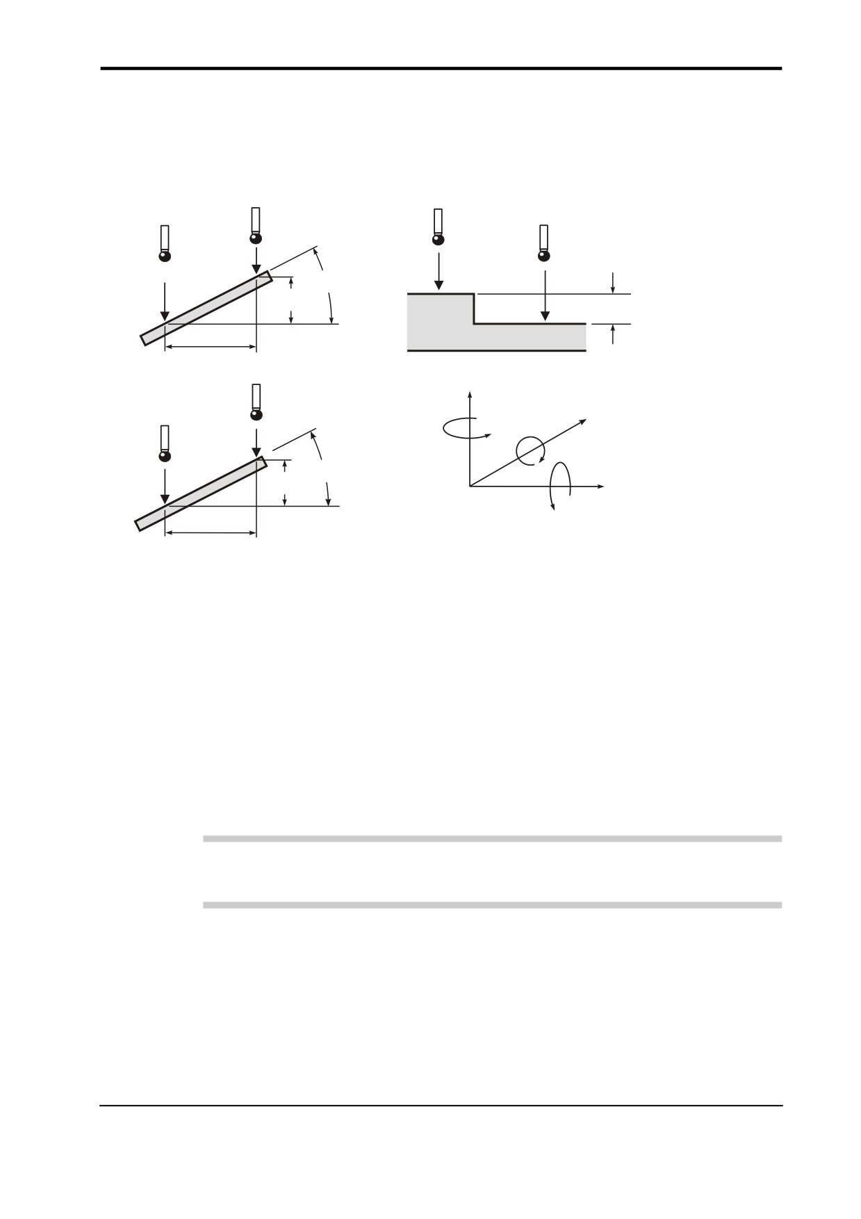
Additional cycles
9-29
Determining feature-to-feature data in the Z plane - macro O9834
NOTE:
Angles in the range ±180°
+Aa angles (counter-clockwise)
P2
+Aa
+Zz
Zz
P1
+Dd
Zz
Z+
Y+
P1
+Aa
-Zz
X+
P2
-Dd
Figure 9.15 Determining feature-to-feature data in the Z plane
Description
This is a no-movement macro that is used after two measuring cycles to determine
feature-to-feature data.
Application
Data for P1 and P2 must already be stored in variables #180 to #184, and #185 to #197
for P2, by running suitable measuring cycles.
NOTE: The order P1 and P2 is important, because the data calculated is that of P2 with
respect to P1.
Values for P1 are obtained by programming G65 P9834 without any inputs after the first
measuring cycle.
Values for P2 are obtained by running a second measuring cycle, and the feature-to-
feature data is established by programming G65 P9834 with suitable inputs after the
second measuring cycle.
Publication No. H-2000-6222
9-30
Additional cycles
Format
G65 P9834 Zz [Ee Ff Hh Mm Ss Tt Uu Vv Ww]
or
G65 P9834 Aa Zz [Bb Ww]
or
G65 P9834 Dd Zz [Bb Ww]
or
G65 P9834 (with no inputs)
where [ ] denote optional inputs
Examples
G65 P9834 Z50. E0.005 F0.8 H0.2 M0.2 S1.T20. U.5 V.5 W2.
or
G65 P9834 A45.005 Z50. B2. W2.
or
G65 P9834 D50.005 Z50. B2. W2.
or
65 P9834 (with no inputs)
NOTES:
1.
Updating a tool offset with T input is only possible if O9811 is used for P2 data.
Otherwise an alarm (T INPUT NOT ALLOWED) results.
2.
Angles. These are with respect to the XY. Use angles in the range ±180 degrees.
4.
When G65P9834 (without any inputs) is used, then the following data is stored:
from
#185
to
#180
#186
#181
#187
#182
#188
#183
#189
#184
Inputs
Aa Zz or Dd Zz inputs
1.
+Dd/-Dd values should be used to indicate the direction of P2 with respect to P1.
2.
+Aa angles (counter-clockwise).
3.
Angles between ±180 degrees.
Publication No. H-2000-6222
Additional cycles
9-31
Zz only input
1.
+Zz/-Zz values should be used to indicate the direction of P2 with respect to P1.
Compulsory inputs
Aa
a = The angle of P2 with respect to P1 measured from the XY plane (angles
between ±180 degrees).
Zz
z = The nominal incremental distance in the Z axis.
or
Dd
d = The exact distance between P1 and P2 measured in the XY plane.
Zz
z = The nominal incremental distance in the Z axis.
or
(No inputs)
This is used to store output data of the last cycle for P1 data.
Optional inputs
Bb
b = The angle tolerance of the surface, e.g. 30 degrees ±1 degree.
Hh
h = The tolerance value of the feature dimension being measured.
Mm m = The true position tolerance of a feature. A cylindrical zone about the
theoretical position.
Ss
s = The work offset number which will be set.
The work offset number will be updated.
S1 to S6 (G54 to G59)
S0 (external work offset).
S110 to S129 (G110 to G129) additional offsets option.
S154.01 to S154.99 (G154 P1 to G154 P99) additional offsets option.
New work offset = active work offset + error.
New external offset = external offset + error.
Tt
t =
The tool offset number to be updated.
Ww w = Print data
1.
= Increment the feature number only.
2.
= Increment the component number, and reset the feature number.
For optional inputs Ee, Ff, Uu and Vv, see Chapter 3, “Optional inputs”.
Publication No. H-2000-6222
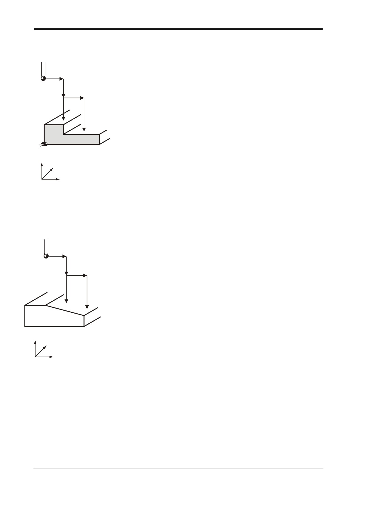
9-32
Additional cycles
Example 1
1
Measuring the incremental distance between two surfaces
2
1.
G65P9810X30.Y50.F3000
Protected positioning move.
5
2.
G65P9810Z30.
Protected positioning move.
3 and 4
3.
G65P9811Z20.
P1 20 mm (0.787 in) surface.
6 and 7
4.
G65P9834
Store data.
5.
G65P9810X50.
Move to new position.
Z
6.
G65P9811Z15.
P2 15 mm (0.591 in) surface.
Y
X
7.
G65P9834Z-5.H.1
Feature to feature at -5.0 mm
(-0.197 in).
Figure 9.16
Probe movements
Example 2
Measuring an angled surface
1.
G65P9810X30.Y50.F3000
Protected positioning move.
1
2
2.
G65P9810Z30.
Protected positioning move.
5
3 and 4
3.
G65P9811Z20.
P1 at 20 mm (0.787 in) position.
6 and 7
4.
G65P9834
Store data.
5.
G65P9810X77.474
Move to new position.
Z
Y
6.
G65P9811Z10.
P2 at 10 mm (0.394 in) position.
X
And either this
7.
G65P9834D27.474Z-10.B.5
Measure slope -20 degrees
(clockwise) angle tolerance ±5
Figure 9.17
degrees.
Probe movements
Or this
7.
G65P9834A-20.Z-10.B.5
Publication No. H-2000-6222