Inspection Plus software for Haas machining centres. Programming manual (H-2000-6222-0A-B) - page 3
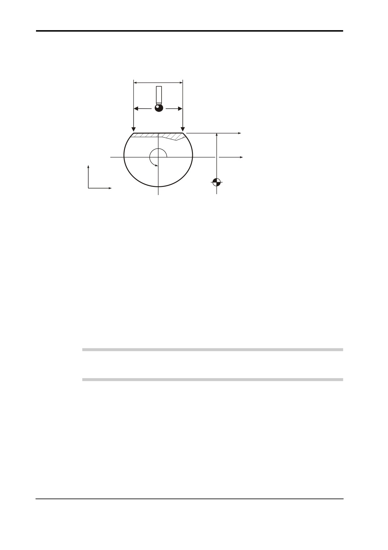
Measuring cycles
7-5
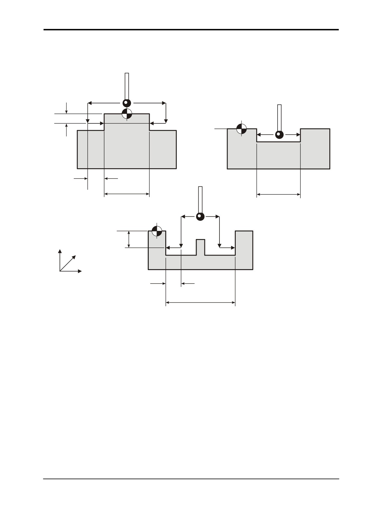
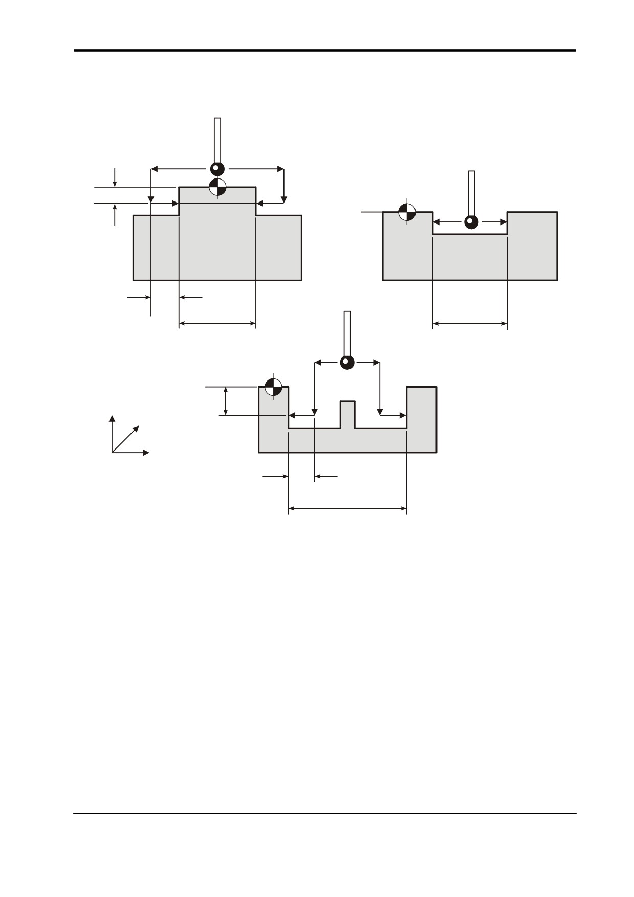
Web / pocket measurement - macro O9812
Z0
Zz
Z0
Rr
Xx, Yy
Xx, Yy
Z0
Zz
Z
Y
X
R-r
Xx, Yy
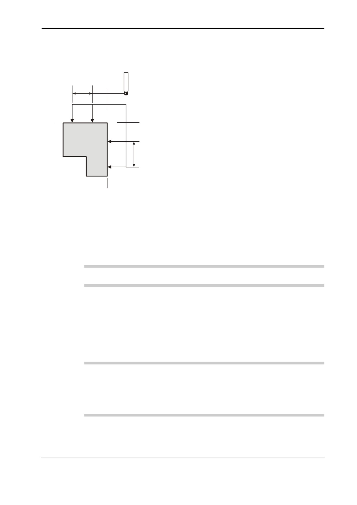
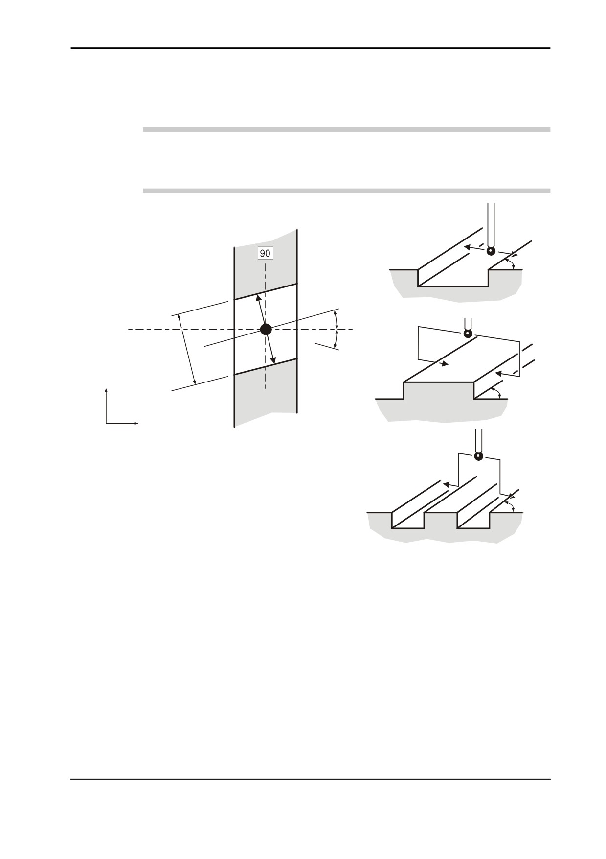
Figure 7.3 Measurement of a web or pocket feature
Description
This cycle measures a web or pocket feature. It uses two measuring moves along the X Y
axis.
Application
Position the probe to the expected centre line of the feature and a suitable position in the
Z axis with the probe and probe offset active. Run the cycle with suitable inputs as
described.
Publication No. H-2000-6222
7-6
Measuring cycles
Format
G65 P9812 Xx [Ee Ff Hh Mm Qq Rr Ss Tt Uu Vv Ww]
or
G65 P9812 Yy [Ee Ff Hh Mm Qq Rr Ss Tt Uu Vv Ww]
or
G65 P9812 Xx Zz [Ee Ff Hh Mm Qq Rr Ss Tt Uu Vv Ww]
or
G65 P9812 Yy Zz [Ee Ff Hh Mm Qq Rr Ss Tt Uu Vv Ww]
where [ ] denote optional inputs
Example: G65 P9812 X50. Z100. E0.005 F0.8 H0.2 M.2 Q10. R10. S1. T20. U.5 V.5 W2.
Compulsory inputs
Xx
x = Nominal size of feature when measured in the X axis.
or
Yy
y = Nominal size of feature when measured in the Y axis.
Zz
z = The absolute Z axis position when measuring a web feature. If this is
omitted a pocket cycle is assumed.
Optional inputs
Hh
h = The tolerance value of a feature dimension being measured.
Mm m = The true position tolerance of a feature. A cylindrical zone about the
theoretical position.
Qq
q = The probe's overtravel distance for use when the default values are
unsuitable. The probe will then travel beyond the expected position when
it searches for a surface. Default values are 4 mm (0.16 in) in the Z axis
and 10 mm (0.394 in) in the X,Y axis.
Rr
r =
This is an incremental dimension that is used in external features, e.g.
bosses and webs, to give a radial clearance from the nominal target
surface prior to a Z axis move. Default value is 5 mm (0.200 in).
R-r
-r = This is similar to Rr, except that the clearance is applied in the opposite
direction to force an internal web cycle. Default value is 5 mm (0.200 in).
Publication No. H-2000-6222
Measuring cycles
7-7
Ss
s = The work offset number which will be set.
The work offset number will be updated.
S1 to S6 (G54 to G59)
S0 (external work offset).
S110 to S129 (G110 to G129) additional offsets option.
S154.01 to S154.99 (G154 P1 to G154 P99) additional offsets option.
New work offset = active work offset + error.
New external offset = external offset + error.
Tt
t =
This is the tool offset number to be updated.
Ww w = Print data
1.
= Increment the feature number only.
2.
= Increment the component number, and reset the feature number.
For optional inputs Ee, Ff, Uu, and Vv, see Chapter 3, “Optional inputs”.
Outputs
The feature measurements will be stored in variables #185 to #199 (see Chapter 4,
“Variable outputs”).
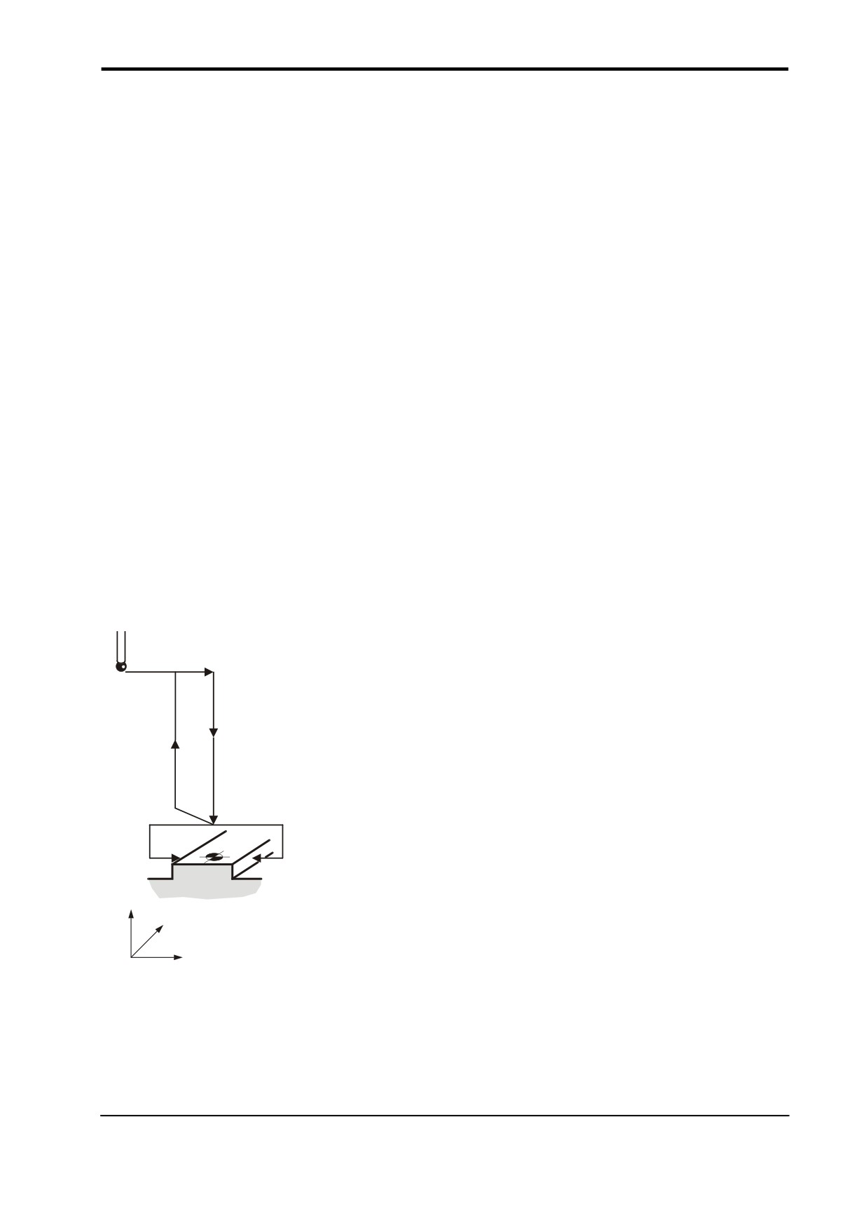
Example 1
Web measurement
1
2
1.
T01M06
Select the probe.
9
3
2.
G54X0Y0
Start position.
4
8
3.
G43H1Z100.
Activate offset 1, go to 100 mm (3.94 in)
above.
5
7
4.
G65P9832
Spin the probe on (includes M19), or M19
6
for spindle orientation.
5.
G65P9810Z10.F3000
Protected positioning move.
6.
G65P9812X50.Z-10.S2
Measure a 50.0 mm (1.968 in) wide web.
Z
Y
7.
G65P9810Z100.
Protected positioning move.
X
8.
G65P9833
Spin the probe off (where applicable).
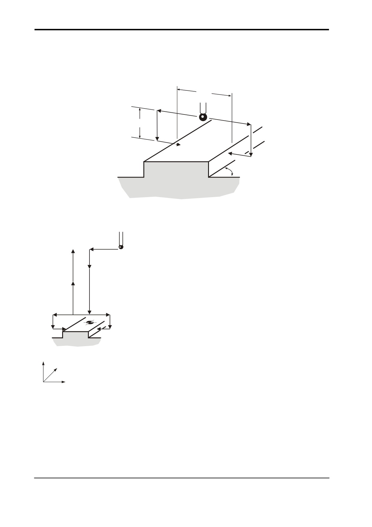
Figure 7.4
Probe movements
9.
G28Z100.
Reference return.
continue
The feature centre line in the X axis is stored in the work offset 02 (G55).
Publication No. H-2000-6222
7-8
Measuring cycles
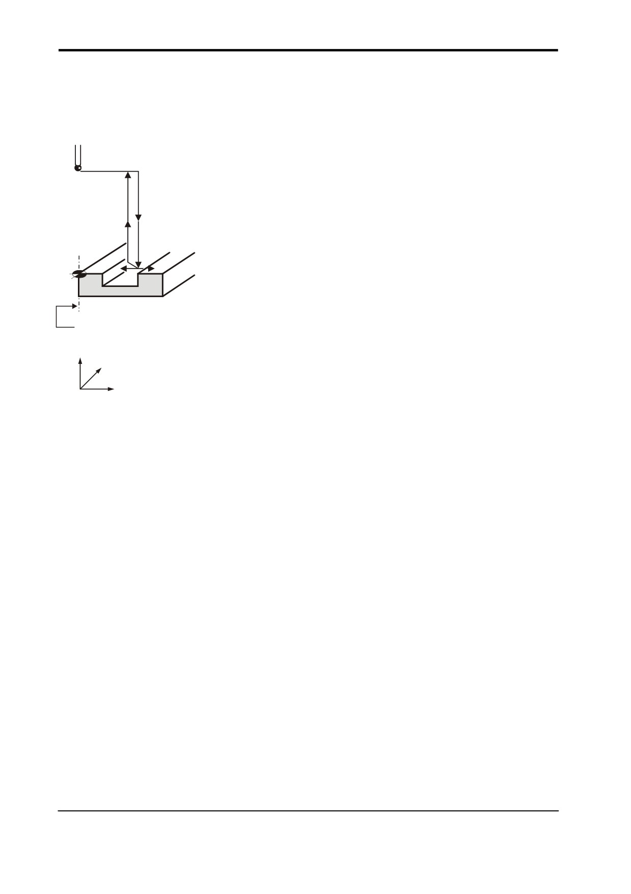
Example 2
Pocket measurement (referred datum)
1
2
1.
T01M06
Select the probe.
3
9
2.
G54X100.Y50.
Start position.
4
8
3.
G43H1Z100.
Activate offset 1, go to 100 mm (3.94 in).
5
7
6
4.
G65P9832
Spin the probe on (includes M19), or M19
for spindle orientation.
5.
G65P9810Z-10.F3000.
Protected positioning move.
6.
G65P9812X30.S2
Measure a 30.0 mm (1.181 in) wide
G55
pocket.
Z
Y
7.
G65P9810Z100.
Protected positioning move.
X
8.
G65P9833
Spin the probe off (where applicable).
Figure 7.5
9.
G28Z100.
Reference return.
Probe movements
continue
The error of centre line is referred to the datum point X0 and the revised X0 position is set
in work offset 02 (G55).
Publication No. H-2000-6222
Measuring cycles
7-9
Bore / boss measurement - macro O9814
Z0
Zz
Z0.0
Rr
Dd dia
Dd dia
Z0
Zz
Z
Y
X
R-r
Dd dia
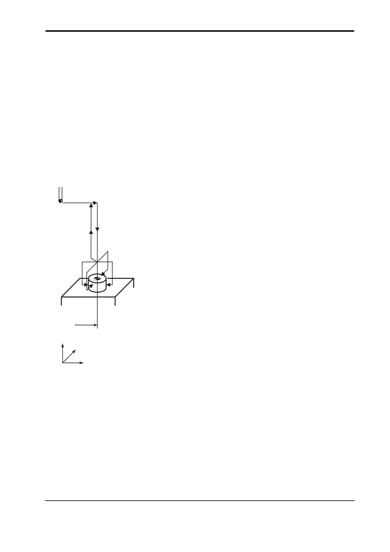
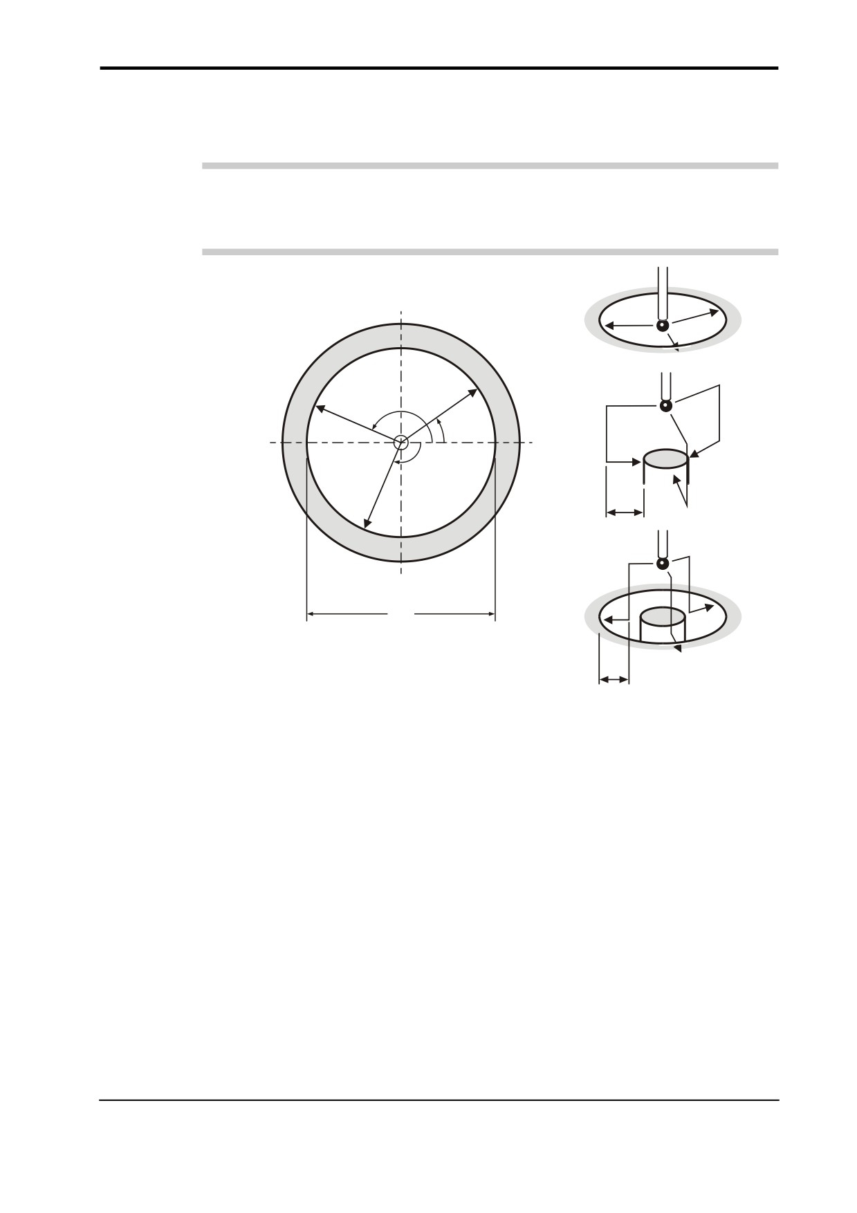
Figure 7.6 Measurement of a bore or boss feature
Description
This cycle measures a bore or boss feature. It uses four measuring moves along the X Y
axis.
Application
Position the probe to the expected centre line of the feature and a suitable position in the
Z axis with the probe and probe offset active. Run the cycle with suitable inputs as
described.
Publication No. H-2000-6222
7-10
Measuring cycles
Format
G65 P9814 Dd [Ee Ff Hh Mm Qq Rr Ss Tt Uu Vv Ww]
or
G65 P9814 Dd Zz [Ee Ff Hh Mm Qq Rr Ss Tt Uu Vv Ww]
where [ ] denote optional inputs
Example: G65 P9814 D50.005 Z100. E0.005 F0.8 H0.2 M.2 Q10. R10. S1. T20. U.5 V.5 W2.
Compulsory inputs
Dd
d = Nominal size of the feature.
Zz
z = The absolute Z axis position when measuring a boss feature. If this is
omitted, a bore cycle is assumed.
Optional inputs
Hh
h =
The tolerance value of a feature dimension being measured.
Mm
m =
The true position tolerance of a feature. A cylindrical zone about the
theoretical position.
Qq
q =
The probe's overtravel distance for use when the default values are
unsuitable. The probe will then travel beyond the expected position when
it searches for a surface. Default values are 4 mm (0.16 in) in the Z axis
and 10 mm (0.394 in) in the X,Y axis.
Rr
r =
This is an incremental dimension that is used in external features, e.g.
bosses and webs, to give a radial clearance from the nominal target
surface prior to a Z axis move. Default value is 5 mm (0.200 in).
R-r
-r =
This is similar to Rr, except that the clearance is applied in the opposite
direction to force an internal boss cycle. Default value is 5 mm (0.200 in).
Ss
s =
The work offset number which will be set.
The work offset number will be updated.
S1 to S6 (G54 to G59)
S0 (external work offset).
S110 to S129 (G110 to G129) additional offsets option.
S154.01 to S154.99 (G154 P1 to G154 P99) additional offsets option.
New work offset = active work offset + error.
New external offset = external offset + error.
Tt
t =
This is the tool offset number to be updated.
Publication No. H-2000-6222
Measuring cycles
7-11
Ww w = Print data
1.
= Increment the feature number only.
2.
= Increment the component number, and reset the feature number.
For optional inputs Ee, Ff, Uu, and Vv, see Chapter 3, “Optional inputs”.
Outputs
The feature measurements will be stored in variables #185 to #199 (see Chapter 4,
“Variable outputs”).
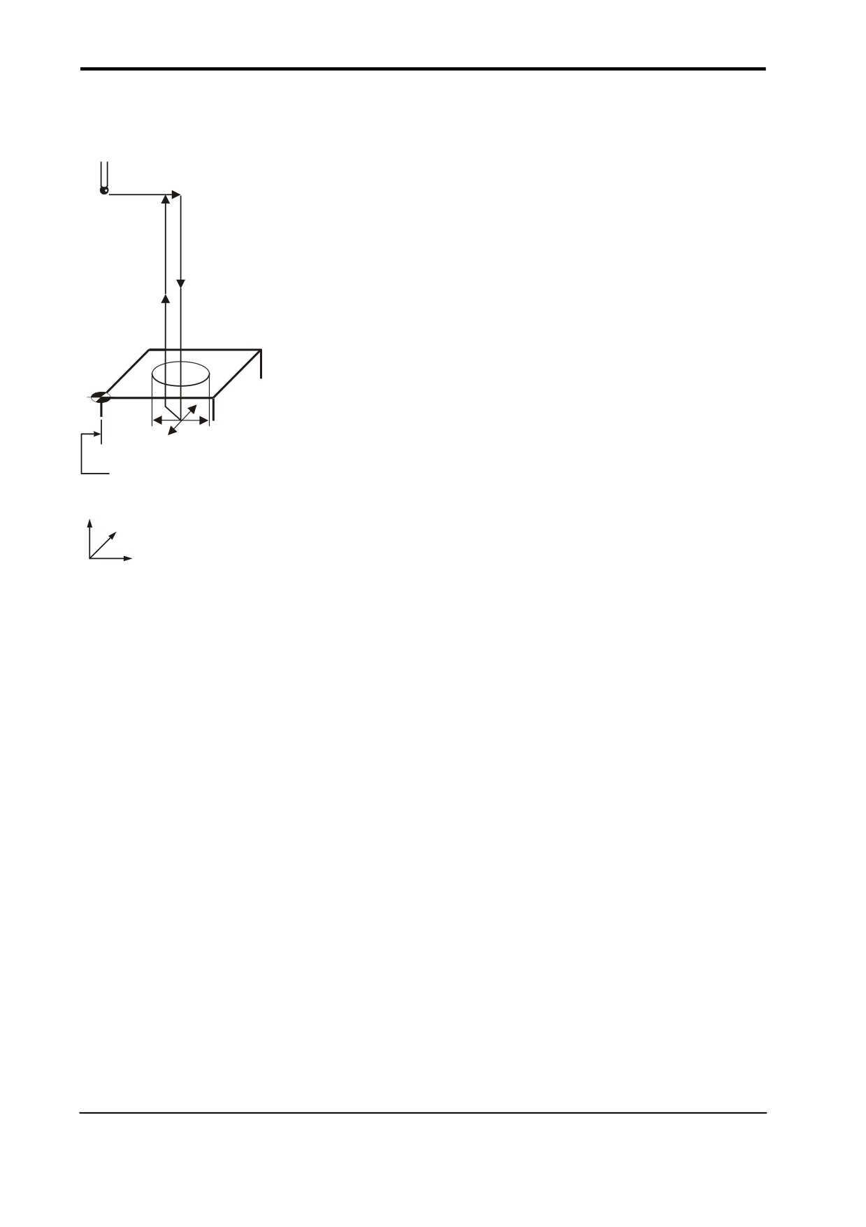
Example 1
Boss measurement
1
2
1.
T01M06
Select the probe.
3
9
2.
G54X0Y0
Start position.
4
8
3.
G43H1Z100.
Activate offset 1, go to 100 mm
5
7
(3.94 in).
6
4.
G65P9832
Spin the probe on (includes M19), or
M19 for spindle orientation.
5.
G65P9810Z10.F3000
Protected positioning move.
6.
G65P9814D50.Z-10.S2.R10.
Measure a 50.0 mm (1.968 in)
diameter boss.
G55
7.
G65P9810Z100.
Protected positioning move.
Z
8.
G65P9833
Spin the probe off (when applicable).
Y
9.
G28Z100.
Reference return.
X
Figure 7.7
continue
Probe movements
The feature centre line in the X and Y axis is stored in the work offset 02 (G55).
Publication No. H-2000-6222
7-12
Measuring cycles
Example 2
Bore measurement (referred datum)
1
2
1.
T01M06
Select the probe.
3
2.
G54X100.0Y100.
Start position.
9
4
3.
G43H1Z100.
Activate offset 1, go to 100 mm
8
(3.94 in).
5
7
4.
G65P9832
Spin the probe on (includes M19), or
M19 for spindle orientation.
5.
G65P9810Z-10.F3000
Protected positioning move.
6
6.
G65P9814D30.S2
Measure a 30.0 mm (1.181 in)
diameter bore.
G55
7.
G65P9810Z100.
Protected positioning move.
Z
8.
G65P9833
Spin the probe off (when applicable)
Y
9.
G28Z100.
Reference return
X
Figure 7.8
continue
Probe movements
The error of centre line is referred to the datum point X0, Y0 and the revised X0, Y0
position is set in work offset 02 (G55).
Publication No. H-2000-6222
Measuring cycles
7-13
Finding an internal corner - macro O9815
Xx
Yy
Yy
Ii
Jj
Y
X
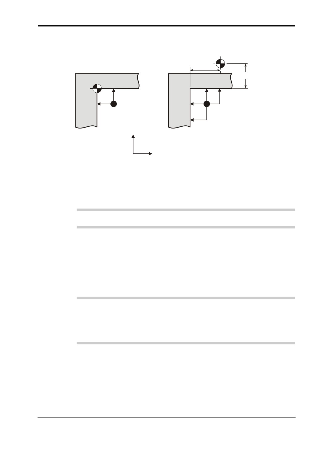
Figure 7.9 Finding an internal corner position
Description
This cycle is used to establish the corner position of a feature.
NOTE: A true corner intersection can be found, even if the corner is not 90 degrees.
Application
The probe must be positioned with its tool offset active at a start position as shown in the
figure above. The probe measures the Y axis surface first and then measures the X axis
surface. The probe then returns to the start position.
Errors occurring during the cycle return the probe to the start position.
NOTE: If the I and J inputs are missing, only two gauging moves occur. The corner
feature is assumed to be parallel to the axes.
If either I or J are missing then three gauging moves occur and the corner feature is
assumed to be 90 degrees.
Format
G65 P9815 Xx Yy [Bb Ii Jj Mm Qq Ss Uu Ww]
where [ ] denote optional inputs
Example: G65 P9815 X100. Y100. B2. I10. J10. M.2 Q10. S1. U.5 W2.
Publication No. H-2000-6222
7-14
Measuring cycles
NOTE: I and J must be stated in this order if used.
Compulsory inputs
Xx
x = Nominal corner position X axis.
Yy
y = Nominal corner position Y axis.
Optional inputs
Bb
b =
Angle tolerance.
This applies to both X and Y surfaces. It is equal to half the total
tolerance, e.g. ±0.25 degrees = B.25 tolerance.
Ii
I =
Incremental distance to the second probe position along the X axis
(positive value is assumed) (default no move)
Jj
j =
Incremental distance to the second probe position along the Y axis
(positive value is assumed) (default no move).
Mm
m =
The true position tolerance of a feature. A cylindrical zone about the
theoretical position.
Qq
q =
The probe's overtravel distance for use when the default values are
unsuitable. The probe will then travel beyond the expected position when
it searches for a surface. Default values are 4 mm (0.16 in) in the Z axis
and 10 mm (0.394 in) in the X,Y axis.
Ss
s =
The work offset number which will be set.
The work offset number will be updated.
S1 to S6 (G54 to G59)
S0 (external work offset).
S110 to S129 (G110 to G129) additional offsets option.
S154.01 to S154.99 (G154 P1 to G154 P99) additional offsets option.
New work offset = active work offset + error.
New external offset = external offset + error.
Ww
w =
Print data
1.
= Increment the feature number only.
2.
= Increment the component number, and reset the feature number.
For optional inputs Uu, see Chapter 3, “Optional inputs”.
Publication No. H-2000-6222
Measuring cycles
7-15
Outputs
The feature measurements will be stored in variables #185 to #199 (see Chapter 4,
“Variable outputs”).
W2. Component no. +1 feature no. 1
W1 Feature no. +1
The following will be output:
1.
Corner positions
2.
Tolerance if used
3.
Error in the X axis
4.
Error in the Y axis
5.
Work offset no. if used
Ss
The work offset stated will be set such that the nominal X Y positions will be
corrected.
Mm) See Appendix H, “Output flow“ for the general output structure
Uu )
NOTE: #189 is the angle of the X surface and is measured from the X+ axis direction.
#192 is the angle of the Y surface and is also measured from the X+ axis direction.
Publication No. H-2000-6222
7-16
Measuring cycles
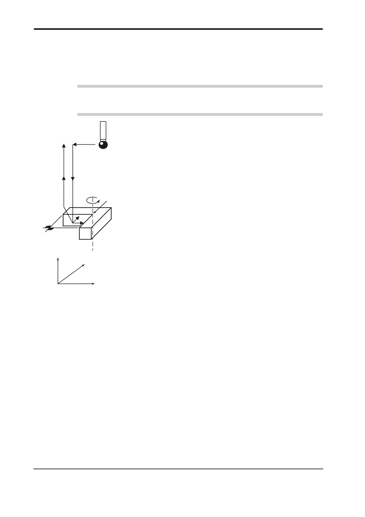
Example
Finding an internal corner
NOTE: Co-ordinate rotation. It is possible to implement rotation using G68/G69 when the
control option is available.
1.
T01M06
Select the probe.
2
1
2.
G54X10.0Y10.
Start position.
3.
G43H1Z100.
Activate offset 1, go to 100 mm
9
3
(3.94 in).
8
4
4.
G65P9832
Spin the probe on (includes M19), or
M19 for spindle orientation.
7
5
11
5.
G65P9810Z-5.F3000
Protected positioning move.
6.
G65P9815X20.Y20.I10.J10.
Corner find.
6
7.
G65P9810Z100.
Protected positioning move.
8.
G65P9833
Spin the probe off (where applicable)
Z
Y
9.
G28Z100.
Reference return.
10.
G17
Select plane.
X
11.
G68X#185Y#186R#189
Set rotational position and angle.
Figure 7.10
Probe movements
continue
machining
continue
12.
G69
Cancel rotation mode.
Publication No. H-2000-6222
Measuring cycles
7-17
Finding an external corner - macro O9816
NOTE:
Ii
c
d
The start point establishes
the distance to the first
measuring position.
a
Yy
NOTE:
b
a and b are equal
c and d are equal
Jj
Xx
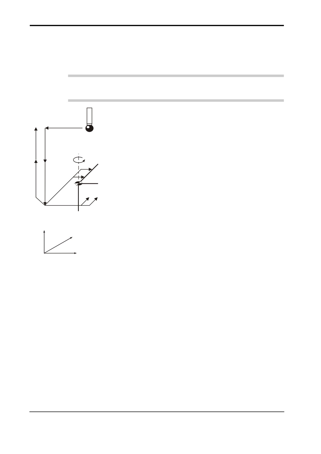
Figure 7.11 Finding an external corner
Description
This cycle is used to establish the corner position of a feature.
NOTE: A true corner intersection can be found, even if the corner is not 90 degrees.
Application
The probe must be positioned with its tool offset active at a start position as shown in the
diagram. The probe measures the Y axis surface first and then measures the X axis
surface. The probe then returns to the start position.
Errors occurring during the cycle return the probe to the start position.
NOTE: If the I and J inputs are missing, only two gauging moves occur. The corner
feature is assumed to be parallel to the axes.
If either I or J are missing then three gauging moves occur and the corner feature is
assumed to be 90 degrees.
Publication No. H-2000-6222
7-18
Measuring cycles
Format
G65 P9816 Xx Yy [Bb Ii Jj Mm Qq Ss Uu Ww]
where [ ] denote optional inputs
Example: G65 P9816 X100. Y100. B2. I10. J10. M.2 Q10. S1. U.5W2.
NOTE: I and J must be stated in this order if used.
Compulsory inputs
Xx
x = Nominal corner position X axis.
Yy
y = Nominal corner position Y axis.
Optional inputs
Bb
b =
Angle tolerance. This applies to both X and Y surfaces. It is equal to half
the total tolerance, e.g. ±0.25 degrees = B.25 tolerance.
Ii
I =
Incremental distance to the second probe position along the X axis (a
positive value is assumed). The default is no move.
Jj
j =
Incremental distance to the second probe position along the Y axis (a
positive value is assumed). The default is no move.
Mm
m =
The true position tolerance of a feature. A cylindrical zone about the
theoretical position.
Qq
q =
The probe's overtravel distance for use when the default values are
unsuitable. The probe will then travel beyond the expected position when
it searches for a surface. Default values are 4 mm (0.16 in) in the Z axis
and 10 mm (0.394 in) in the X,Y axis.
Ss
s =
The work offset number which will be set.
The work offset number will be updated.
S1 to S6 (G54 to G59)
S0 (external work offset).
S110 to S129 (G110 to G129) additional offsets option.
S154.01 to S154.99 (G154 P1 to G154 P99) additional offsets option.
New work offset = active work offset + error.
New external offset = external offset + error.
Publication No. H-2000-6222
Measuring cycles
7-19
Ww w = Print data
1.
= Increment the feature number only.
2.
= Increment the component number, and reset the feature number.
For optional inputs Uu, see Chapter 3, ”Optional inputs”.
Outputs
The feature measurements will be stored in variables #185 to #199 (see Chapter 4,
“Variable outputs”).
W2. Component no. + 1, feature no. set to 1.
W1. Feature no. +1
The following will be output:
1.
Corner positions
2.
Tolerance if used
3.
Error in the X axis
4.
Error in the Y axis
5.
Work offset no. if used
Ss
The work offset stated will be set such that the nominal X Y positions will be
corrected.
Mm) See Appendix H, “Output flow” for the general output structure.
Uu )
NOTE: #189 is the angle of the X surface and is measured from the X+ axis direction.
#192 is the angle of the Y surface and is also measured from the X+ axis direction.
Publication No. H-2000-6222
7-20
Measuring cycles
Example
Finding an external corner
NOTE: Co-ordinate rotation. It is possible to implement rotation using G68/G69 when the
control option is available.
1.
T01M06
Select the probe.
2
1
2.
G54X-10.Y-10.
Start position.
3.
G43H1Z100.
Activate offset 1, go to 100 mm
9
3
(3.94 in).
4
4.
G65P9832
Spin the probe on (includes M19), or
8
M19 for spindle orientation.
11
5.
G65P9810Z-5.F3000
Protected positioning move.
7
5
6.
G65P9816X0Y0I10.J10.
Corner find.
6
7.
G65P9810Z100.
Protected positioning move.
8.
G65P9833
Spin the probe off (where
Z
applicable).
Y
9.
G28Z100.
Reference return.
X
10.
G17
Select plane.
11.
G68X#185Y#186R#189
Set corner position and angle.
Figure 7.12
Probe movements
Continue machining
12.
G69
Cancel co-ordinate rotation mode.
Publication No. H-2000-6222
Vector measuring cycles
8-1
Chapter 8
Vector measuring cycles
This chapter describes how to use the vector measuring cycle macros. The probe stylus
ball radius must be calibrated using macro O9804 (see Chapter 6, “Calibration cycles”)
before using the macros described here. Do not use macro O9803 to calibrate the probe's
stylus.
Contained in this chapter
Angle single surface measurement - macro O9821
8-2
Angled web or pocket measurement - macro O9822
8-5
3-point bore or boss measurement - macro O9823
8-9
Publication No. H-2000-6222
8-2
Vector measuring cycles
Angle single surface measurement - macro O9821
NOTE: The probe must have recently been calibrated using the vector stylus ball radius
macro O9804 (described in Chapter 6, “Calibration cycles”) before using this cycle. Do not
use macro O9803 to calibrate the probe.
NOTE:
Angles in the range ±180°
+Aa angles (counter-clockwise)
Dd
Y
90°
Aa
X
180°
0°
-90°
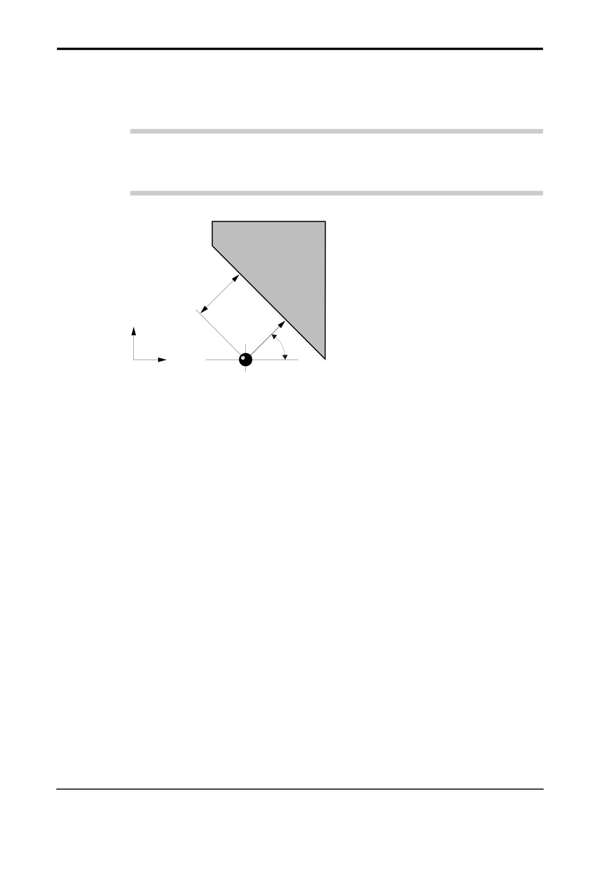
Figure 8.1 Measuring an angled surface
Description
This cycle measures a surface feature using one vectored measuring move along the X Y
axis.
Application
Position the probe to the expected reference point of the feature and a suitable position in
the Z axis with the probe and probe offset active. Run the cycle with suitable inputs as
described.
Format
G65 P9821 Aa Dd [Ee Ff Hh Mm Qq Ss Tt Uu Vv Ww]
where [ ] denote optional inputs
Example: G65 P9821 A45.005 D50.005 E0.005 F0.8 H0.2 M0.2 Q10. S1. T20. U.5 V.5 W2.
Publication No. H-2000-6222
Vector measuring cycles
8-3
Compulsory inputs
Aa
a = Direction of probe measurement measured from the X+ axis direction.
Dd
d = Nominal distance to the surface (radial).
Optional inputs
Hh
h =
The tolerance value of a feature dimension being measured.
Mm
m =
The true position tolerance of a feature. A cylindrical zone about the
theoretical position.
Qq
q =
The probe's overtravel distance for use when the default values are
unsuitable. The probe then travels beyond the expected position when it
searches for a surface.
Default values are 4 mm (0.16 in) in the Z axis and 10 mm (0.4 in) in the
X,Y axis.
Ss
s=
The work offset number which will be set.
The work offset number will be updated.
S1 to S6 (G54 to G59)
S0 (external work offset).
S110 to S129 (G110 to G129) additional offsets option.
S154.01 to S154.99 (G154 P1 to G154 P99) additional offsets option.
New work offset = active work offset + error.
New external offset = external offset + error.
Tt
t =
This is the tool offset number to be updated
Ww
w =
Print data
1.
= Increment the feature number only.
2.
= Increment the component number, and reset the feature number.
For optional inputs Ee, Ff, Uu, and Vv, see Chapter 3, “Optional inputs”.
Outputs
The feature measurements will be stored in variables #185 to #199 (see Chapter 4,
“Variable outputs”).
Publication No. H-2000-6222
8-4
Vector measuring cycles
Example
Angle single surface measurement
50.0
Y
45°
X
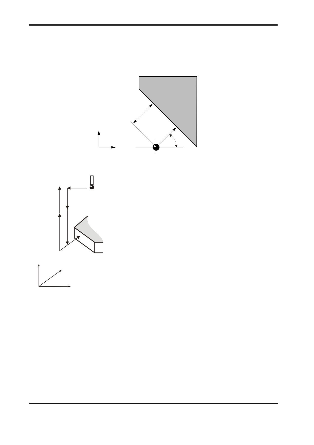
Figure 8.2 Measuring a single angled surface
1.
T01M06
Select the probe.
2
1
2.
G54X-40.Y20.
Start position.
3
9
4
3.
G43H1Z100.
Activate offset 1, go to 100 mm
8
(3.94 in).
5
4.
G65P9832
Spin the probe on (includes M19), or
7
M19 for spindle orientation.
5.
G65P9810Z-8.F3000
Protected positioning move to start
6
position.
Z
Y
6.
G65P9821A45.D50.T10 Single surface measure.
7.
G65P9810Z100.
Protected positioning move.
X
8.
G65P9833
Spin the probe off (when applicable).
Figure 8.3
Probe movements
9.
G28Z100.
Reference return.
The tool radius offset (10) is updated by the error of surface position.
Publication No. H-2000-6222
Vector measuring cycles
8-5
Angled web or pocket measurement - macro O9822
NOTE: The probe must have recently been calibrated using the vector stylus ball radius
macro O9804 (described in Chapter 6, “Calibration cycles”) before using this cycle. Do not
use macro O9803 to calibrate the probe.
Aa
Aa
180
0
A - a
Dd
Y+
Aa
X+
NOTE:
Angles in the range ±180°
+Aa angles (counter-clockwise)
Aa
Figure 8.4 Measuring an angled web or pocket
Description
This cycle measures a web or pocket feature using two vectored measuring moves along
the X Y axis.
Application
Position the probe to the expected centre line of the feature and a suitable position in the
Z axis with the probe and probe offset active. Run the cycle with suitable inputs as
described.
Publication No. H-2000-6222
8-6
Vector measuring cycles
Format
G65 P9822 Aa Dd [Ee Ff Hh Mm Qq Rr Ss Tt Uu Vv Ww]
or
G65 P9822 Aa Dd Zz [Ee Ff Hh Mm Qq Rr Ss Tt Uu Vv Ww]
where [ ] denote optional inputs
Example: G65 P9822 A45.005 D50.005 Z50. E0.005 F0.8 H0.2 M0.2 Q10. R10. S1. T20.
U.5 V.5 W2.
Compulsory inputs
Aa
a = Angle of the surface to be measured from the X+ axis direction.
Dd
d = Nominal size of the feature.
Zz
z = The absolute Z axis position when measuring a web feature. If this is
omitted a pocket cycle is assumed.
Optional inputs
Hh
h =
The tolerance value of a feature dimension being measured.
Mm
m =
The true position tolerance of a feature. A cylindrical zone about the
theoretical position.
Qq
q =
The probe's overtravel distance for use when the default values are
unsuitable. The probe then travels beyond the expected position when it
searches for a surface. Default values are 4 mm (0.16 in) in the Z axis
and 10 mm (0.394 in) in the X,Y axis.
Rr
r =
This is an incremental dimension that is used in external features, e.g.
bosses and webs, to give a radial clearance from the nominal target
surface prior to a Z axis move. Default value is 5 mm (0.200 in).
R-r
-r =
This is similar to Rr, except that the clearance is applied in the opposite
direction to force an internal web cycle. Default value is 5 mm (0.200 in).
Ss
s =
The work offset number which will be set.
The work offset number will be updated.
S1 to S6 (G54 to G59)
S0 (external work offset).
S110 to S129 (G110 to G129) additional offsets option.
S154.01 to S154.99 (G154 P1 to G154 P99) additional offsets option.
New work offset = active work offset + error.
New external offset = external offset + error.
Tt
t =
This is the tool offset number to be updated
Publication No. H-2000-6222
Vector measuring cycles
8-7
Ww
Print data
1.
= Increment the feature number only.
2.
= Increment the component number, and reset the feature number.
For optional inputs Ee, Ff, Uu, and Vv, see Chapter 3, “Optional inputs”.
Outputs
The feature measurements will be stored in variables #185 to #199 (see Chapter 4,
“Variable outputs”).
Publication No. H-2000-6222
8-8
Vector measuring cycles
Example
Angle web measurement
50.0
-10
30°
Figure 8.5 Measuring an angled web
1.
T01M06
Select the probe.
2
1
2.
G54X0Y0
Start position.
9
3
3.
G43H1Z100.0
Activate offset 1, go to
4
100 mm (3.94 in).
8
4.
G65 P9832
Spin the probe on (includes
5
M19), or M19 for spindle
7
orientation.
6
5.
G65P9810Z10.F3000
Protected positioning move.
6.
G65P9822A30.D50.Z-10.S2
Measure a 50.0 mm
(1.9685 in) wide web at 30
degrees.
Z
7.
G65P9810Z100.
Protected positioning move.
Y
8.
G65P9833
Spin the probe off (when
X
applicable).
Figure 8.6
9.
G28Z100.
Reference return
Probe movements
Continue
The feature centre line in the X axis is stored in the work offset S02 (G55).
Publication No. H-2000-6222
Vector measuring cycles
8-9
3-point bore or boss measurement - macro O9823
NOTE: The probe must have recently been calibrated using the vector stylus ball radius
macro O9804 (described in Chapter 6, “Calibration cycles”) before using this cycle. Do not
use macro O9803 to calibrate the probe.
90°
Bb
Aa
180°
0°
Cc
Rr
-90°
Dd
NOTE:
Angles in the range ±180°
+Aa angles (counter-clockwise)
R-r
Figure 8.7 3-point bore or boss measurement
Description
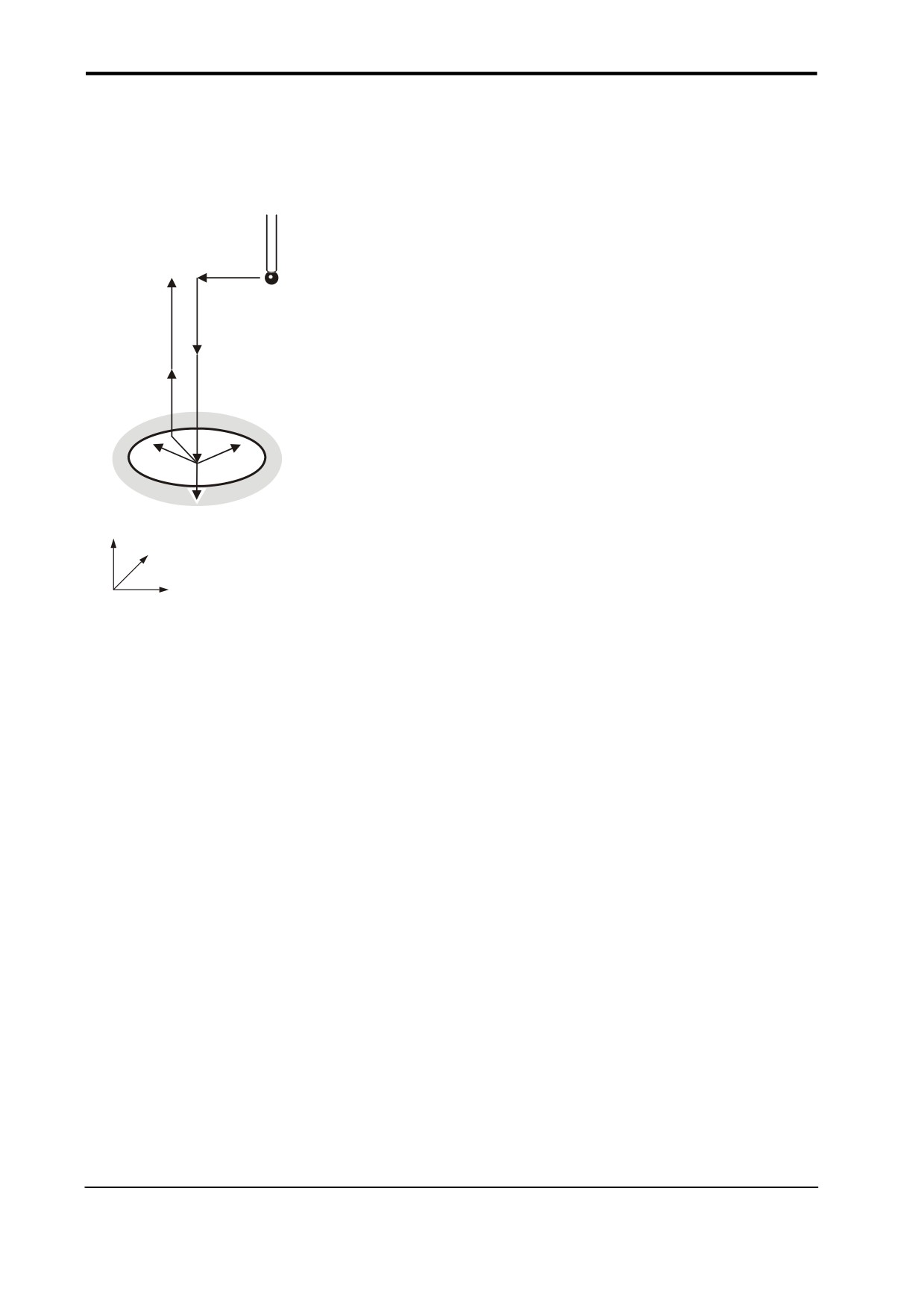
This cycle measures a bore or boss feature using three vectored measuring moves along
the X Y axis.
Application
Position the probe to the expected centre line of the feature and a suitable position in the
Z axis with the probe and probe offset active. Run the cycle with suitable inputs as
described.
Publication No. H-2000-6222
8-10
Vector measuring cycles
Format
G65 P9823 Aa Bb Cc Dd [Ee Ff Hh Mm Qq Rr Ss Tt Uu Vv Ww]
or
G65 P9823 Aa Bb Cc Dd Zz [Ee Ff Hh Mm Qq Rr Ss Tt Uu VvWw]
where [ ] denote optional inputs
Example: G65 P9823 A45.005 B150.0 C35.005 D50.005 Z50. E.005 F0.8 H0.2 M0.2
Q10. R10. S1. T20.U.5 V.5W2.
Compulsory inputs
Aa
a = The first angle for vector measurement, measured from the X+ axis
direction.
Bb
b = The second angle for vector measurement, measured from the X+ axis
direction.
Cc
c = The third angle for vector measurement, measured from the X+ axis
direction.
Dd
d = Nominal size of feature.
Zz
z = The absolute Z axis position, when measuring a boss feature. If this is
omitted, a bore cycle is assumed.
Optional inputs
Hh
h = The tolerance value of a feature dimension being measured.
Mm m = The true position tolerance of a feature. A cylindrical zone about the
theoretical position.
Qq
q = The probe's overtravel distance for use when the default values are
unsuitable. The probe then travels beyond the expected position when it
searches for a surface. Default values are 4 mm (0.16 in) in the Z axis
and 10 mm (0.394 in) in the X,Y axis.
Rr
r =
This is an incremental dimension that is used in external features, e.g.
bosses and webs, to give a radial clearance from the nominal target
surface prior to a Z axis move. Default value is 5 mm (0.200 in).
R-r
-r = This is similar to Rr, except that the clearance is applied in the opposite
direction to force an internal boss cycle. Default value is 5 mm (0.200 in).
Publication No. H-2000-6222
Vector measuring cycles
8-11
Ss
s = The work offset number which will be set.
The work offset number will be updated.
S1 to S6 (G54 to G59)
S0 (external work offset).
S110 to S129 (G110 to G129) additional offsets option.
S154.01 to S154.99 (G154 P1 to G154 P99) additional offsets option.
New work offset = active work offset + error.
New external offset = external offset + error.
Tt
t =
This is the tool offset number to be updated.
Ww w = Print data
1.
= Increment the feature number only.
2.
= Increment the component number, and reset the feature number.
For optional inputs Ee, Ff, Uu, and Vv, see Chapter 3, “Optional inputs”.
Outputs
The feature measurements will be stored in variables #185 to #199 (see Chapter 4,
“Variable outputs”).
Publication No. H-2000-6222
8-12
Vector measuring cycles
Example
3-point bore measurement (referred datum)
1.
T01M06
Select the probe.
2
1
2.
G54X100.Y100.
Start position.
3
3.
G43H1Z100.
Activate offset 1 go to 100 mm
9
(3.94 in).
4
4.
G65 P9832
Spin the probe on (includes
8
M19), or M19 for spindle
7
5
orientation.
5.
G65P9810Z-10.F3000
Protected positioning.
6
6.
G65P9823D30.A30.B150.C-90. S2
Measure a 30.0 mm (1.181 in)
diameter bore.
Z
7.
G65P9810Z100.
Protected positioning move.
Y
8.
G65P9833
Spin the probe off (when
X
applicable).
Figure 8.8
9.
G28Z100.
Reference return
Probe movements
Continue
The error of centre line is referred to the datum point X0,Y0 and the revised X0,Y0
position is set in work offset 02 (G55).
Publication No. H-2000-6222
Additional cycles
9-1
Chapter 9
Additional cycles
The Inspection Plus software contains a number of macro cycles that cannot be
categorised under the headings used in previous chapters of this manual (chapters 5 to 8
inclusive). This chapter describes how to use these cycles.
Contained in this chapter
4th axis X measurement - macro O9817
9-2
4th axis Y measurement - macro O9818
9-5
Bore / boss on PCD measurement - macro O9819
9-8
Stock allowance - macro O9820
9-11
Storing multi-stylus data - macro O9830
9-16
Loading multi-stylus data - macro O9831
9-19
Turning the probe on - macro O9832
9-22
Turning the probe off - macro O9833
9-23
Determining feature-to-feature data in the XY plane - macro O9834
9-24
Determining feature-to-feature data in the Z plane - macro O9834
9-29
Updating the SPC tool offset - macro O9835
9-33
Optimising a probing cycle - macro O9836
9-35
Angle measurement in the X or Y plane - macro O9843
9-38
Publication No. H-2000-6222
9-2
Additional cycles
4th axis X measurement - macro O9817
Xx
NOTE:
Angle correction to 4th axis
+ (positive) counter-clockwise
- (negative) clockwise
X0 (BO)
Z+
Zz
X+
Figure 9.1 4th axis X measurement
Description
The purpose of this macro is to find the slope of a surface between two points Z1 and Z2
and make the necessary correction by indexing a ‘rotary axis’ to compensate. It also
updates a ‘work zero point’ for that axis if required.
Application
The 4th axis must be positioned to the expected angular position of the feature (i.e.
surface normal to the Z axis). The cycle finds the error of surface position, and then
adjusts the axis work offset or checks a tolerance.
NOTE: It is normally necessary on most machines to re-state the work offset and move to
the angular position after the cycle to make the new work offset active.
Format
G65 P9817 Xx Zz [Qq Bb Ss Ww]
where [ ] denote optional inputs.
Example: G65 P9817 X100. Z50. Q10. B2. S1. W2.
Publication No. H-2000-6222