Inspection Plus software for Haas machining centres. Programming manual (H-2000-6222-0A-B) - page 6
Tolerances
D-3
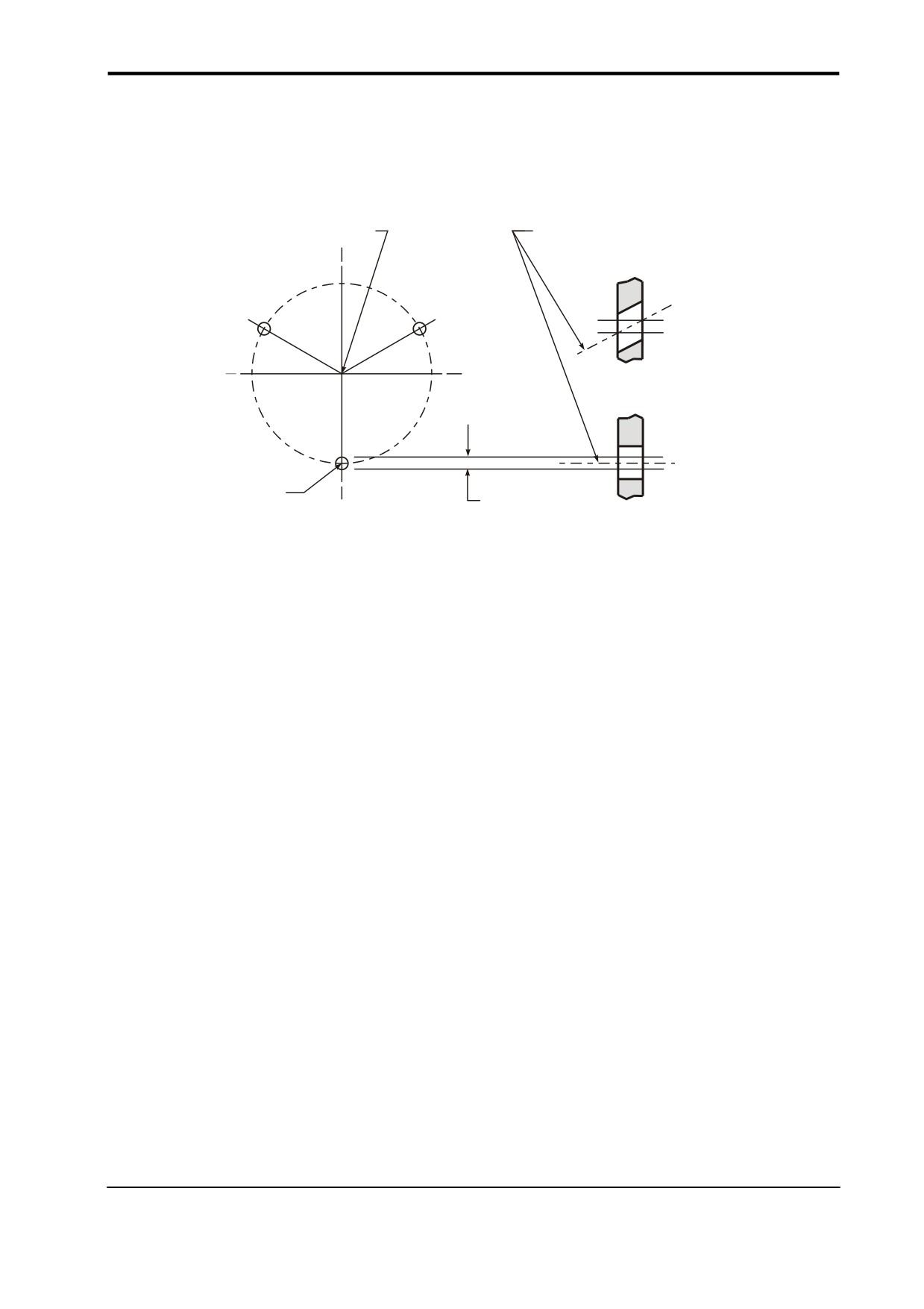
True position tolerances
For a true position tolerance (Mm input), see Figure D.2 below.
Axis of datum
Possible axes
True position
Tol. 0.1
(Mm input)
Figure D.2 Cylinders centred on true positions
Publication No. H-2000-6222
D-4
Tolerances
This page intentionally left blank.
Publication No. H-2000-6222
Experience values Ee
E-1
Appendix E
Experience values Ee
Contained in this appendix
Experience values Ee
E-2
Reason for using this option
E-2
Publication No. H-2000-6222
E-2
Experience values Ee
Experience values Ee
The measured size can be adjusted by an amount stored in a spare tool offset.
Example
Measure a 40 mm diameter and update tool offset 20
G65P9814 D40. T20 E21
An experience value stored in tool offset 21 will
be applied to the measured size.
NOTE: The experience value is always added
to the measured size.
Also refer to Appendix F, “Additional spare tool
offsets”.
Reason for using this option
Component clamping forces in some applications can influence the measured size.
Therefore, an adjustment value to relate measurement to a traceable standard, such as a
co-ordinate measuring machine, is desirable. Thermal effects can also be compensated
by this means.
Publication No. H-2000-6222
Additional spare tool offsets
F-1
Appendix F
Additional spare tool offsets
Contained in this appendix
Additional spare tool offsets
F-2
Publication No. H-2000-6222
F-2
Additional spare tool offsets
Additional spare tool offsets
The range of tool offsets available is extended with the Type C tool offset installed on the
machine.
Each tool offset is actually four registers. These are tool length geometry and wear, plus
tool diameter / radius geometry and wear. There may be limitations on the maximum
values allowable in the wear offsets set by the OEM. In practice, it may only be possible to
use the geometry registers.
These can be addressed in the macro call line as follows:
Tool length geometry offsets
E1 to E100
Tool diameter / radius geometry offsets
E401 to E500
From the figures you can see that 400 can be added to the tool offset number to address
the additional range of registers.
These additional tool offset registers can safely be used for both 'Ee' experience values
and also with the SPC macro (O9835) 'Mm' input provided. The tool offset number is not
used as a normal tool offset location.
Publication No. H-2000-6222
Printing a macro output
G-1
Appendix G
Printing a macro output
Contained in this appendix
Example of printing a macro output
G-2
Publication No. H-2000-6222
G-2
Printing a macro output
Example of printing a macro output
---------------------------------------------------------------------
COMPONENT NO 31
FEATURE NO 1
---------------------------------------------------------------------
POSN R79.0569 ACTUAL 79.0012 TOL TP 0.2000 DEV -0.0557
POSN X-45.0000 ACTUAL -45.1525 TOL TP 0.2000 DEV -0.1525
POSN Y-65.0000 ACTUAL -64.8263 TOL TP 0.2000 DEV 0.1737
+++++OUT OF POS+++++ ERROR TP 0.1311 RADIAL
ANG -124.6952 ACTUAL -124.8578 DEV -0.1626
---------------------------------------------------------------------
COMPONENT NO 31
FEATURE NO 2
---------------------------------------------------------------------
SIZE D71.0000 ACTUAL 71.9072 TOL 0.1000 DEV 0.9072
+++++OUT OF TOL+++++ ERROR 0.8072
POSN X-135.0000 ACTUAL -135.3279 DEV -0.3279
POSN Y-65.0000 ACTUAL -63.8201 DEV 1.1799
Publication No. H-2000-6222
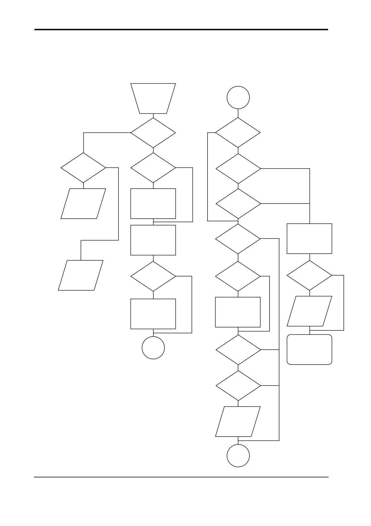
Output flow (bore/boss and web/pocket cycles)
H-1
Appendix H
Output flow (bore/boss and web/pocket
cycles)
Contained in this appendix
Output flow (bore/boss and web/pocket cycles)
H-2
Publication No. H-2000-6222
H-2
Output flow (bore/boss and web/pocket cycles)
Output flow (bore/boss and web/pocket cycles)
Measure
N10
Y
If error flag
N
#199 NEO
If U input
If #199
Y
If E input
N
If size
NE 2
error
Y
Probe fail
Size adjust
If pos
#3000
experience
error
N11
If H input
N
Flag #198=3
Output variables
#185 to #199
Probe
Y
N
If size
N
If flag only
open
If W input
#3000
error
#170.4=1
Upper
Flag #198=1
tolerance
Print data to
RS232 port
exceeded
#3006
N10
Y
If flag only
END
#170.4=1
N
If size
error
Out of
tolerance
#3006
#3000 alarms must reset machine
#3006 cycle start to continue
N13
Publication No. H-2000-6222
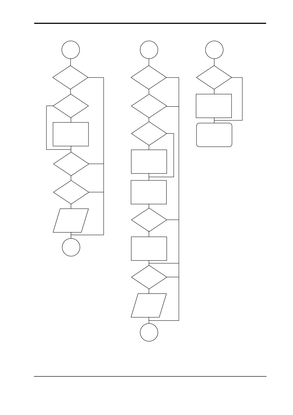
Output flow (bore/boss and web/pocket cycles)
H-3
N13
N15
N19
N
N
N
If M input
If T input
If S input
N
If pos
If V band
N
Work offset
error
exceeded
update
Flag #198=2
Y
If F input
END
Set F=1
If flag only
Y
#198=1
N
If pos
Update tool offset
error
error x F
Out of
N
If radius
position
too large
#3006
N15
Flag #198=5
If flag only
Y
#170.4=1
Out of
tolerance
#3006
N19
Publication No. H-2000-6222
H-4
Output flow (bore/boss and web/pocket cycles)
This page intentionally left blank.
Publication No. H-2000-6222
Use of macro variables
I-1
Appendix I
Use of macro variables
Contained in this appendix
Local variables
I-2
Common variables
I-2
Common retained variables
I-3
Publication No. H-2000-6222
I-2
Use of macro variables
Local variables
#1 to #32
These are used within each macro as required for calculation etc.
Common variables
#161
Base number for calibration.
#166
Active tool length - calculated in macro O9723.
#167
Modal feedrate value is used in the protected positioning macro (O9810).
#168
Radius too large flag macro O9812, O9814, O9822, O9823 (also used for
temporary ATAN store in macro O9731).
#169
Fast feedrate value. This is set in macro O9724 at 5000 mm/min
(200 in/min) default value.
#170
Setting variable used in macro O9724.
#171
Print, component number (6-digit) increment by 1, with each heading
program #171 = 0 to reset.
#172
Feature number (4-digit) increment by 1, with each print macro call
program #172 = 0 to reset.
#173
Start and end of block position zone normal setting 0.05 mm (0.002 in). If
the skip position is within this zone, the cycle aborts, with a Probe Open
or Probe Fail alarm.
#174
Stored X skip position at the end of the basic move macro O9726
#175
Stored Y skip position at the end of the basic move macro O9726.
#176
Stored Z skip position at the end of the basic move macro O9726.
#177
X average skip position at the end of the X diameter move macro O9721.
#178
Y average skip position at the end of the Y diameter move macro O9722.
#179
Inch/metric multiplier (0.04/1.0)
#180 to #184
Output data #180 to #184 is stored when the feature-to-feature macro
O9834 is used.
#185 to #199
See Chapter 4, “Variable outputs” for an output reference chart.
Publication No. H-2000-6222
Use of macro variables
I-3
Common retained variables
The actual variables available are the limiting factor and depend on the base number used
for adjusting the range of #500 variables used for data storage.
The variable allocation described below assumes that the default base number of 556 (set
in macro O9724) is being used.
#556 (556 + 0)
(XRAD) X calibration radius
#557 (556 + 1)
(YRAD) Y calibration radius
#558 (556 + 2)
(XOFF) X axis stylus offset
#559 (556 + 3)
(YOFF) Y axis stylus offset
#560 (556 + 4)
(Reserved for other software packages)
#561 (556 + 5)
(Reserved for other software packages)
#562 (556 + 6)
Basic move control factor. This is used to control the back-off distance in
the basic move before the final gauge move. It should be fine tuned on
installation to suit the machine. Refer to Figure I.1 for a diagrammatic
representation.
A default value of 0.2 is installed by the software. The actual factor
should normally be between 0 and 1.0. Reduce the value to reduce the
back-off distance.
NOTE: This value can be found by using the optimisation macro O9836.
The value must be set in the Settings macro O9724.
(a)
(c)
(b)
X
#562 (556 + 6)
(BMCF)
X
1
2
3
Move 1 fast feed to find the surface
a = Fast feed
Move 2 recover off the surface
b = Gauge feed (100 mm/min)
Move 3 gauge feed 100 mm/min (3.94 in/min)
c = Return
Figure I.1 Basic move control factor
Publication No. H-2000-6222
I-4
Use of macro variables
#563 (556 +7)
(Reserved for other software packages)
#564 (556 +8)
(Reserved for other software packages)
#565 (556 +9)
Active vector radius used in macros O9821, O9822, O9823
#566 to #597
These are reserved for vector calibration data and multi-
stylus storage as described below:
#566 (30 degree)
#567 (60 degree)
#568 (120 degree)
#569 (150 degree)
Vector calibration data
#570 (210 degree)
#571 (240 degree)
#572 (300 degree)
#573 (330 degree)
#574 to #577
Multi-stylus data K1
#578 to #581
Multi-stylus data K2
#582 to # 589
Vector multi-stylus data K11
#590 to #597
Vector multi-stylus data K12
Publication No. H-2000-6222
General probing applications
J-1
Appendix J
General probing applications
Contained in this appendix
Example 1 - Part identification
J-2
Example 2 - Probe measure every nth component
J-3
Publication No. H-2000-6222
J-2
General probing applications
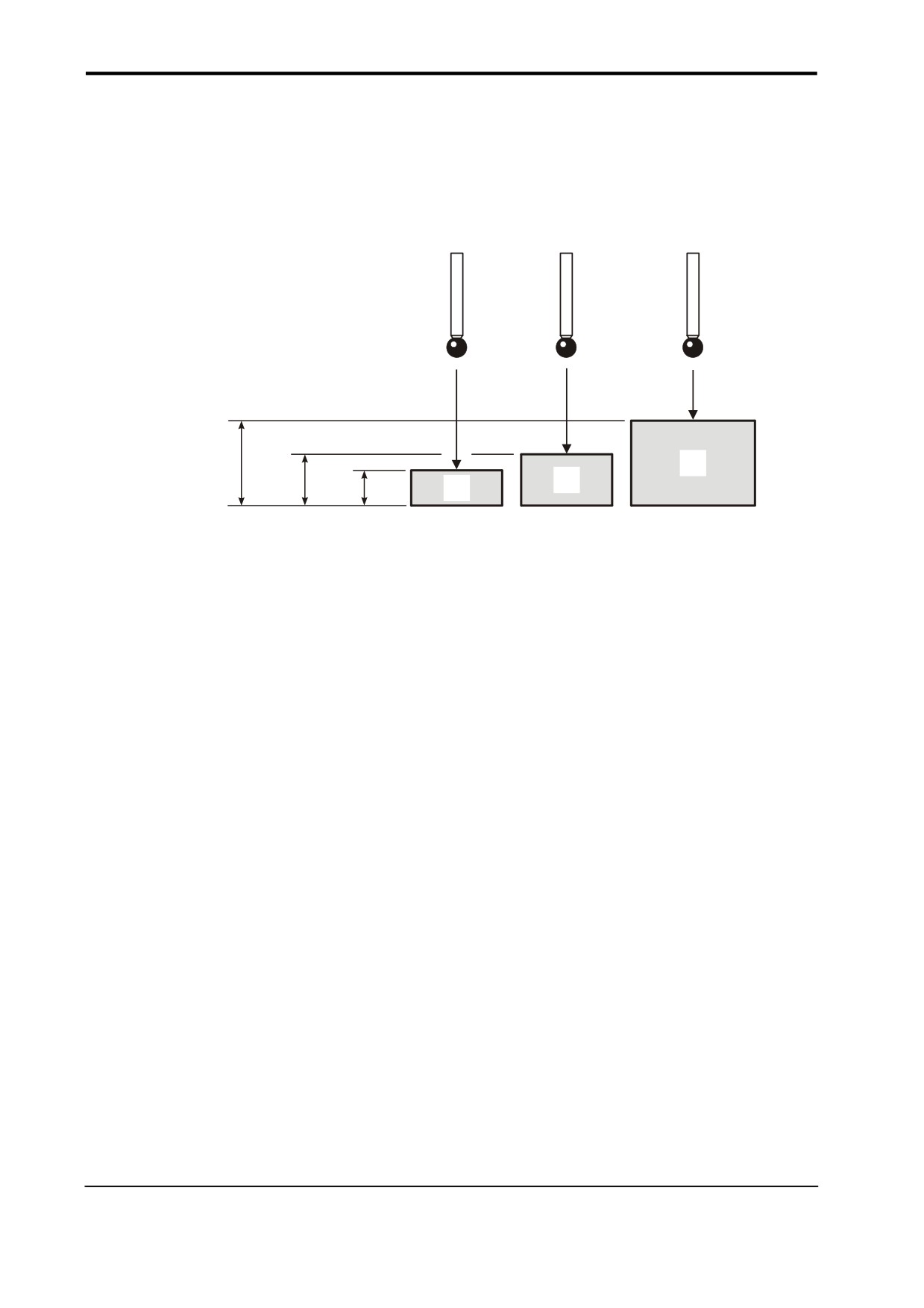
Example 1 - Part identification
If a group of components can be identified by a single feature, a probe can be used to
inspect that feature and decide which component is present. This is done by using data
from the output chart following a measuring program.
74
A
72
B
70
C
Each part surface is known to be within ±0.5
Figure J.1 Part Identification
G65 P9810Z84.F3000
Protected move to start position
G65P9811Z70.
Single surface measure (target C surface)
IF[#187GT73.]GOTO100
If error greater than 73.0 go to N100
IF[#187GT71.]GOTO200
If error greater than 71.0 go to N200
IF[#187GT69.]GOTO300
If error greater than 69.0 go to N300
GOTO400
N100(PROGRAM TO MACHINE A)
continue 'A’ component
GOTO400
N200(PROGRAM TO MACHINE B)
continue 'B' component
GOTO400
N300(PROGRAM TO MACHINE C)
continue 'C' component
Publication No. H-2000-6222
General probing applications
J-3
N400
M30
%
Example 2 - Probe measure every nth component
Often it is a requirement to probe every Nth component in the interests of reducing overall
cycle time.
The following programming method can be employed -
O5000(PART PROGRAM)
#120=0
Reset counter
#121=5
Count limit
N1
(START OF MACHINING)
conventional part programming
N32
(START OF PROBE ROUTINES)
IF[#120LT#121]GOTO33
If counter less than 5 jump to N33
T01M06 (PART INSPECTION) Select inspection probe
probing routines
#120=0
Reset counter to zero
N33
(CONTINUE MACHINING OR END)
#120=#120+1
Increment counter
rest of machining program
M99P1
Return to N1
M30
%
Publication No. H-2000-6222
J-4
General probing applications
This page intentionally left blank.
Publication No. H-2000-6222
One-touch measuring
K-1
Appendix K
One-touch measuring
Contained in this appendix
Introduction
K-2
Why use a one-touch probe cycle?
K-2
Machine distortion
K-2
Comparing cycle times
K-2
Installing the one-touch cycles
K-3
Macro edits
K-3
Measuring the feedrate
K-3
Stand-off and overtravel distance
K-3
System operation
K-4
Using standard skip
K-4
Additional variables used
K-4
Approach feedrates
K-4
Back-off distance #562 (556 + 6)
K-5
False trigger loop
K-5
Acceleration and deceleration allowance
K-5
Q input
K-6
Measuring move detail
K-6
One-touch measuring move logic
K-7
Publication No. H-2000-6222
K-2
One-touch measuring
Introduction
The Inspection Plus software package provides an optional one-touch measuring
capability to supplement the standard two-touch cycles. The one-touch cycles are
intended for use on machines with a fast probe trigger detection ability so that high
measuring feedrates can be used.
Why use a one-touch probe cycle?
A one-touch cycle offers the benefit of reduced cycle times and fewer probe triggers per
cycle. It can be used when the nominal surface position is known to within a small window
of uncertainty.
Machine distortion
The machine is under stress during acceleration and deceleration and therefore the
recorded trigger values may have errors depending on machine tool condition.
Comparing cycle times
A program was prepared to perform five surface measurements as follows:
z
Start 50 mm above the ring gauge
z
Measure a 50 mm bore at 5 mm deep (four cardinal points)
z
Retract to 5 mm above, move over and make a Z measure on top of the ring gauge
z
Retract to 50 mm and return to the centre
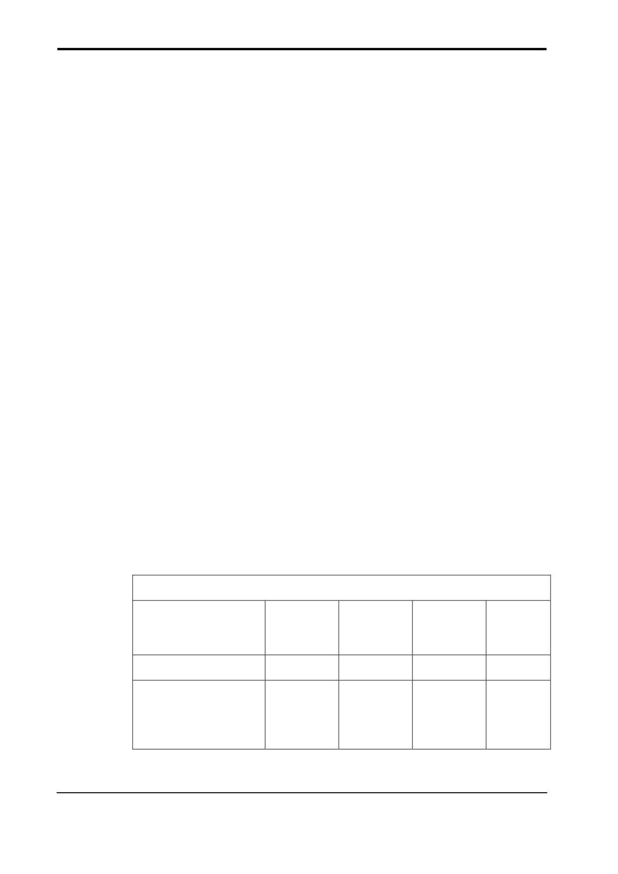
Table K.1 shows cycle time comparisons only. Check for suitable measuring feed rates on
your machine.
Table K.1 Cycle time comparison
Time in
Time in
Time in
Time in
seconds @
seconds @
seconds @
seconds @
500 mm/min
120 mm/min
60 mm/min
30 mm/min
Two-touch cycle
-
-
-
27.6
One-touch cycle
0.5
18.0
18.5
20.0
22.4
Stand-off
1.0
18.2
19.8
22.2
27.2
distance
2.0
18.7
22.4
27.4
37.1
3.0
19.1
24.4
32.2
47.0
Publication No. H-2000-6222

One-touch measuring
K-3
Installing the one-touch cycles
NOTE: The new one-touch basic move macro O9726 is only compatible with the
software supplied with this package. Previous versions are not compatible.
Before installing the one-touch cycles, the standard two-touch cycles must already have
been installed.
The one-touch cycles file (401200885) contains a new one-touch macro O9726. This
should be loaded once the existing two-touch macro O9726 has been deleted from
memory.
Macro edits
Macro O9726, shown below, may be edited for measuring feed rate and stand-
off/overtravel distance values:
:9726(REN BASIC MEASURE -1T)
#9=500*#179(EDIT MEAS FEED)
* Feed - edit 500 value
#28=#9/1000(EDIT ZONE)
accel / deceleration zone
#31=0
IF[#17NE#0]GOTO2
#17=3*#179(EDIT)
* stand off - edit 3 value
N2
NOTE: * denotes this value must be in millimetres
Measuring the feedrate
The default value is 500 mm/min (20 in/min). This may be changed by editing the macro;
for example, if the servo delays are included in the results.
Stand-off and overtravel distance
The default value is 3 mm (0.12 in) in the X, Y and Z axes. Edit the macro to set a new
default or, alternatively, use the ‘Q’ input to override the default value (see page K-6).
Publication No. H-2000-6222
K-4
One-touch measuring
System operation
Refer to the chapters of this manual for a full description of the cycles and their use.
Using standard skip
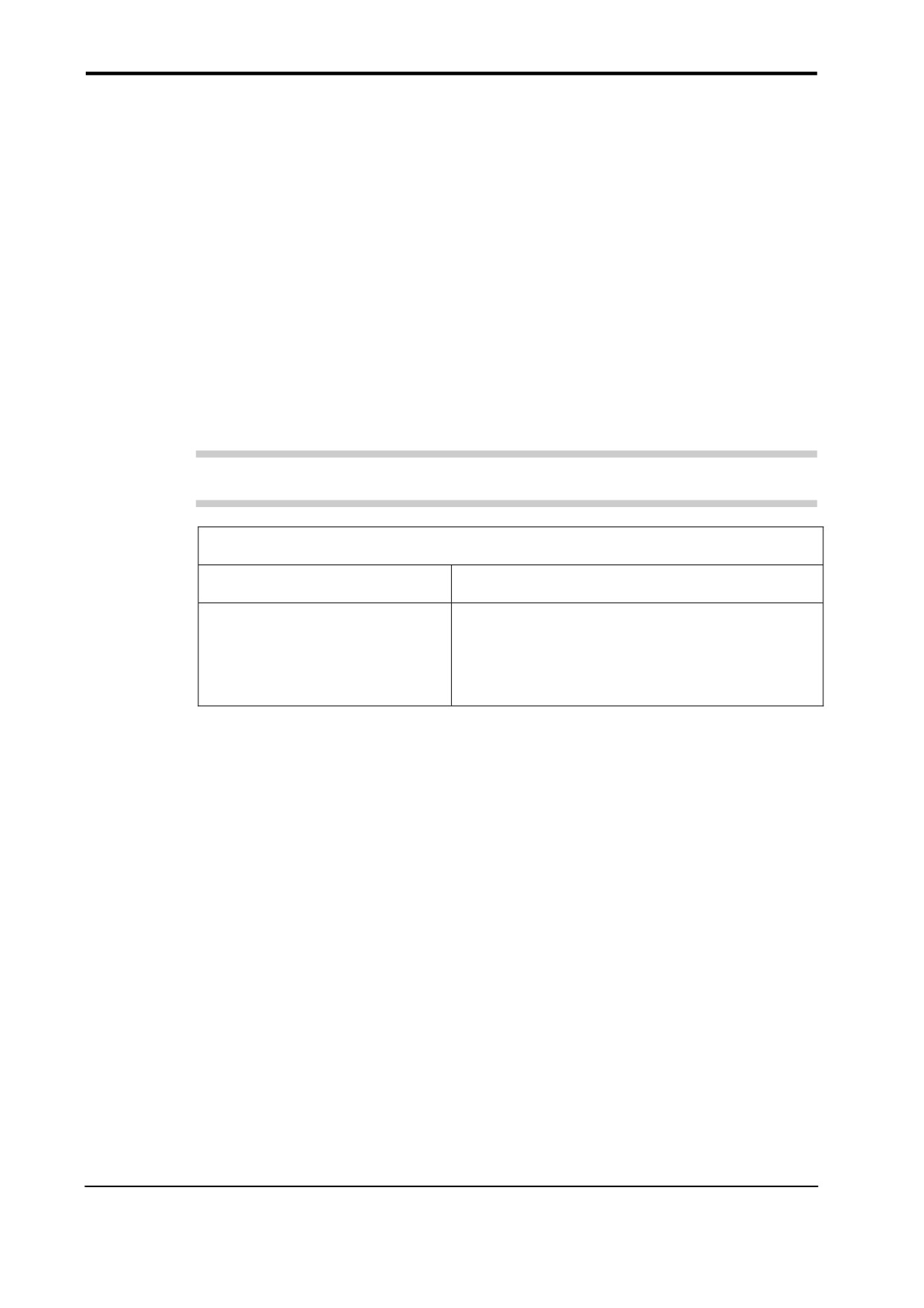
Based on a typical 4 millisecond scan time of the PLC, the standard two-touch method
uses a feedrate of 30 mm/min (1.18 in/min). This gives a measuring uncertainty of
0.002 mm (0.0001 in).
Generally, the two-touch method is well suited to this situation because the back-off
distance can be optimised to provide a short measuring move; for example, less than
0.5 mm (0.020 in). If the one-touch cycles are chosen, the stand-off distance should be
kept small and higher feedrates used if accuracy of measuring is not critical.
NOTE: Measuring uncertainty is related to the feedrate.
Table K.2 Example using the 4 millisecond scan time allowance
Feedrate
Measuring uncertainty
30 mm/min
0.002 mm
60 mm/min
0.004 mm
120 mm/min
0.008 mm
500 mm/min
0.033 mm
Additional variables used
The following additional variables are used by this software:
#174
This is used to store the X axis measured skip position. The value is set in
macro O9726.
#175
This is used to store the Y axis measured skip position. The value is set in
macro O9726.
#176
This is used to store the Z axis measured skip position. The value is set in
macro O9726.
Approach feedrates
The feedrate for the approach to the stand-off position in macro O9726 is set at
3000 mm/min (120 in/min) in the X, Y and Z axes.
Publication No. H-2000-6222

One-touch measuring
K-5
Back-off distance #562 (556 + 6)
This variable is not used in the one-touch cycles.
False trigger loop
At the end of the measuring move a false trigger test is made to see if the probe is
triggered against a surface. If the probe has reseated, the measuring move continues.
Four attempts are made before a “Probe open” alarm occurs.
Acceleration and deceleration allowance
To avoid the possibility of capturing bad data (see Machine distortion on page K-2), the
one-touch basic move sets a checking zone dimension at the start and end of the
measuring move. If the data captured is within these zones, a “Probe open” or “Probe fail”
alarm is generated.
The zone dimension is related to the feedrate and is currently set as follows:
Zone dimension = measuring feedrate / 1000
(i.e. zone factor = 1000)
NOTE: See Macro edits on page K-3 for details of setting the measuring feedrate.
Table K.3 Example of zone allowance using default zone factor 1000
Feedrate
Acceleration and deceleration allowance
30 mm/min
0.03 mm
60 mm/min
0.06 mm
120 mm/min
0.12 mm
500 mm/min
0.50 mm
NOTE: The allowable measuring range is the Q stand-off distance + twice this zone
value.
These values will be suitable in most cases, but optimisation or adjustment may be
required on some machines. A test program can be prepared to test the measuring
accuracy as follows:
1.
Set the measuring feed rate in macro O9726.
2.
Set a large Q value (for example, 3 mm (0.12 in) or greater).
Publication No. H-2000-6222
K-6
One-touch measuring
3.
Prepare a test program to measure a surface.
4.
Measure the surface, ensuring the trigger is in the constant velocity zone (i.e. middle
of measuring move) and record the first measured value.
5.
Make a small STEP adjustment to the programmed surface position (for example,
0.5 mm) and repeat the test, recording the total STEP dimension and the measured
value.
6.
Repeat step 5, making several STEP changes (in the same direction). You will see
when the measured result deviates from the first recorded value. This is the point
where measurement becomes affected by acceleration/deceleration.
Calculate the acceleration/deceleration value:
A = absolute (‘Q’ value - total STEP value)
Calculate the zone factor (see the descriptions above):
Zone factor = measuring feed rate / A
Q input
Qq
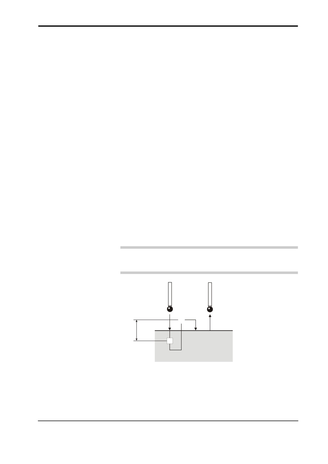
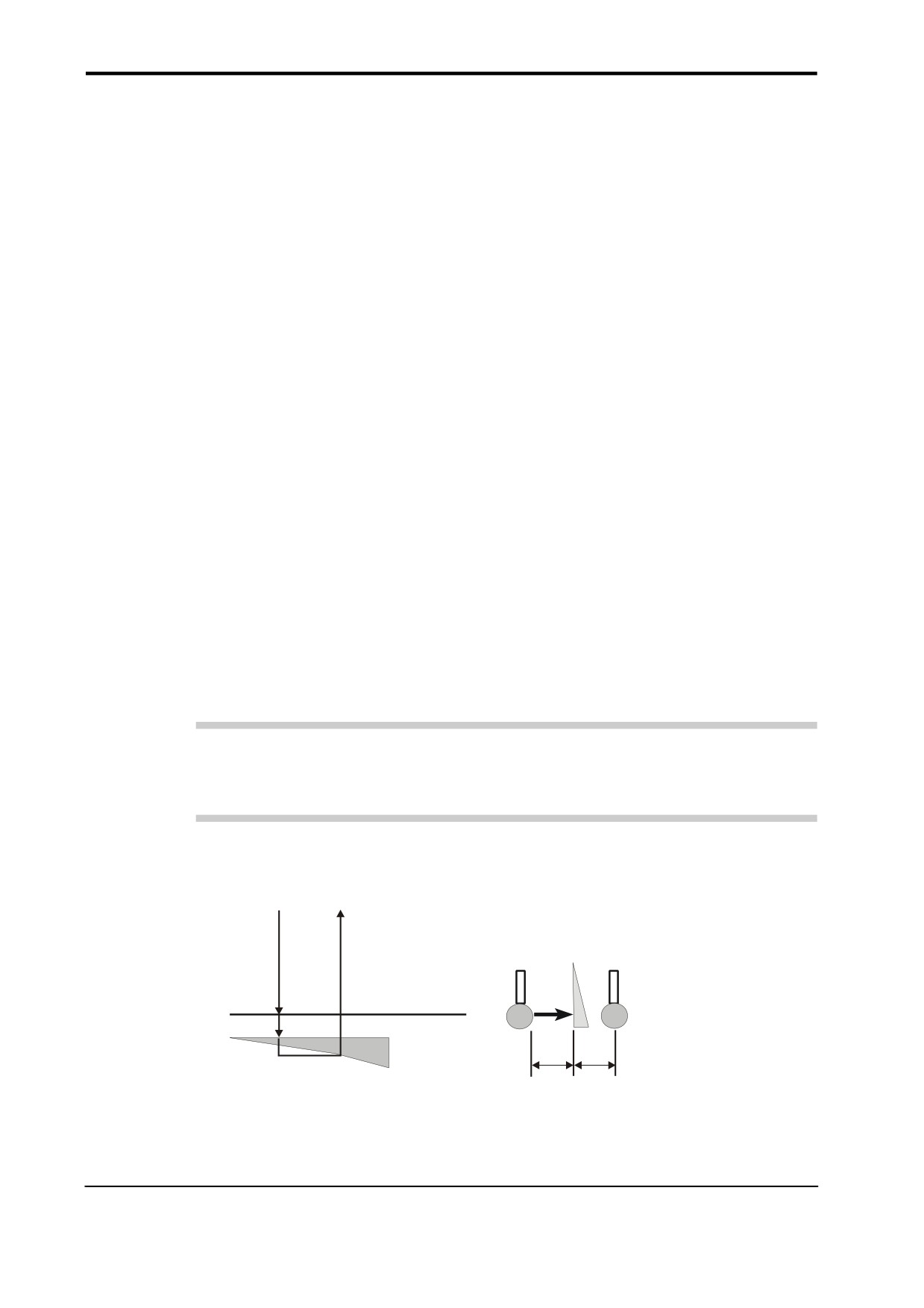
q = Overtravel and stand-off position
The programming input and format is the same whether using one or two-touch cycles.
The exception is that the Q input, which with two-touch cycles controls the overtravel
distance, also controls the stand-off position for the one-touch cycles (see also
Acceleration and deceleration allowance on page K-5).
NOTE: The Q value represents the allowable measuring range. The actual overtravel and
stand-off distance is automatically increased by the acceleration and deceleration
distance (see Acceleration and deceleration allowance on page K-5).
Measuring move detail
One-touch
Stand-off position
Q
Q
Q
Stand-off and overtravel positions
Figure K.1 Measuring move detail
Publication No. H-2000-6222
One-touch measuring
K-7
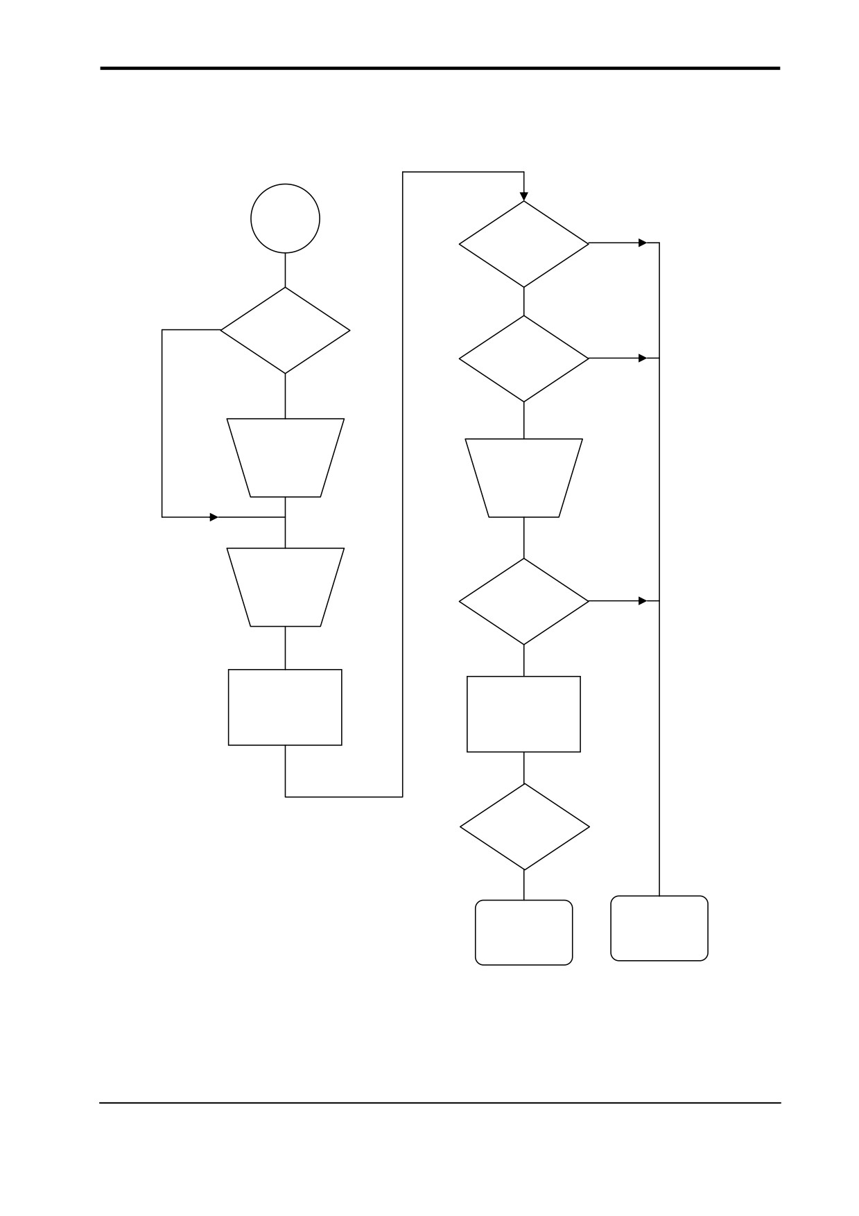
One-touch measuring move logic
Start
Y
IF probe
fail
Y
IF
short move
Y
IF probe
open
Move to
stand-off
False
position
trigger
move
check
Measure
move
IF false
Y
trigger
loop > 4
Store position
Return to start
IF false
trigger
END
Alarms
Publication No. H-2000-6222