FANUC Alpha Series Motors and Modular Drives. Maintenance Manual (GFZ-65165E/02) - page 8
4. HOW TO REPLACE THE FUSES
AND PRINTED CIRCUIT BOARDS
TROUBLESHOOTING
B-65165E/02
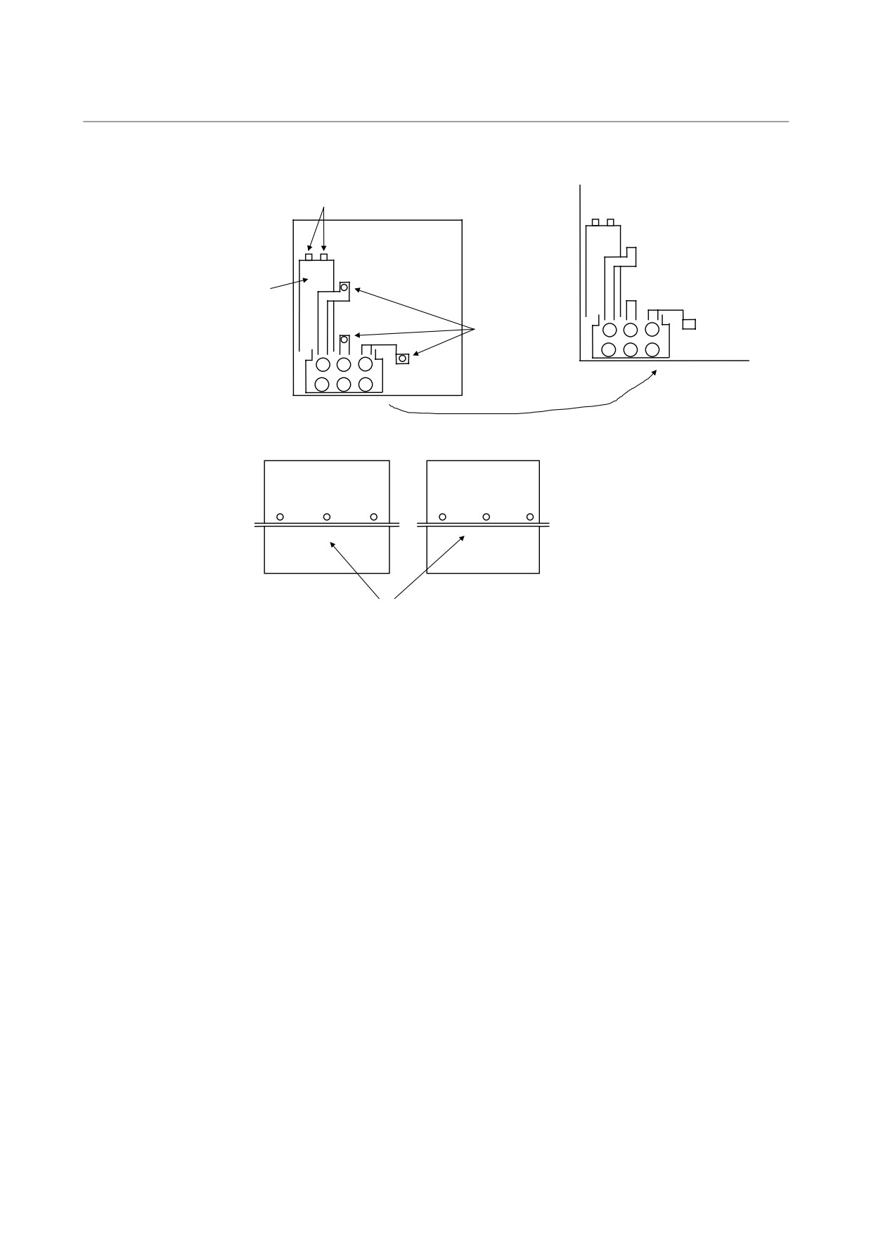
Remove the left side and bottom plates.
Screw (2 × M5)
Wiring board
Electrolytic
capacitor
Screw (3 × M6)
<1> Locate the jumpers that connect the
terminal block TB2 and the wiring
board. Remove the screws (3 ×
M6) holding the jumpers to the
Left side plate
Bottom plate
wiring board.
<2> Remove the screws (2 × M5) that
connect the capacitor and jumpers.
<3> Remove the screws (6 × M4) from
the left side and bottom plates.
<4> Remove the left side and bottom
plates.
(These plates come off
together with the electrolytic
capacitor and terminal block TB2.)
Screw (6 × M4)
- 188 -

4. HOW TO REPLACE THE FUSES
B-65165E/02
TROUBLESHOOTING
AND PRINTED CIRCUIT BOARDS
Remove the power printed circuit board.
<1> Remove the screws that connect the IGBT
and wiring board (9 × M6, 12 × M4).
<2> Remove the screws of the thermostat TH1
(2 × M4).
<3> Remove the screws that connect the wiring
board and heat sink (2 × M4, 1 × M5).
<4> Remove the wiring board.
TH1
Wiring board
FG
Remove the IGBT.
IGBT
- 189 -
4. HOW TO REPLACE THE FUSES
AND PRINTED CIRCUIT BOARDS
TROUBLESHOOTING
B-65165E/02
4.1.5
300-mm Wide Module (with the Connector Module)
Make sure that the recharge-under-way LED (red) is off. View the
recharge-under-way LED (red) from the upper part of the DC link
cover.
LED
Cover
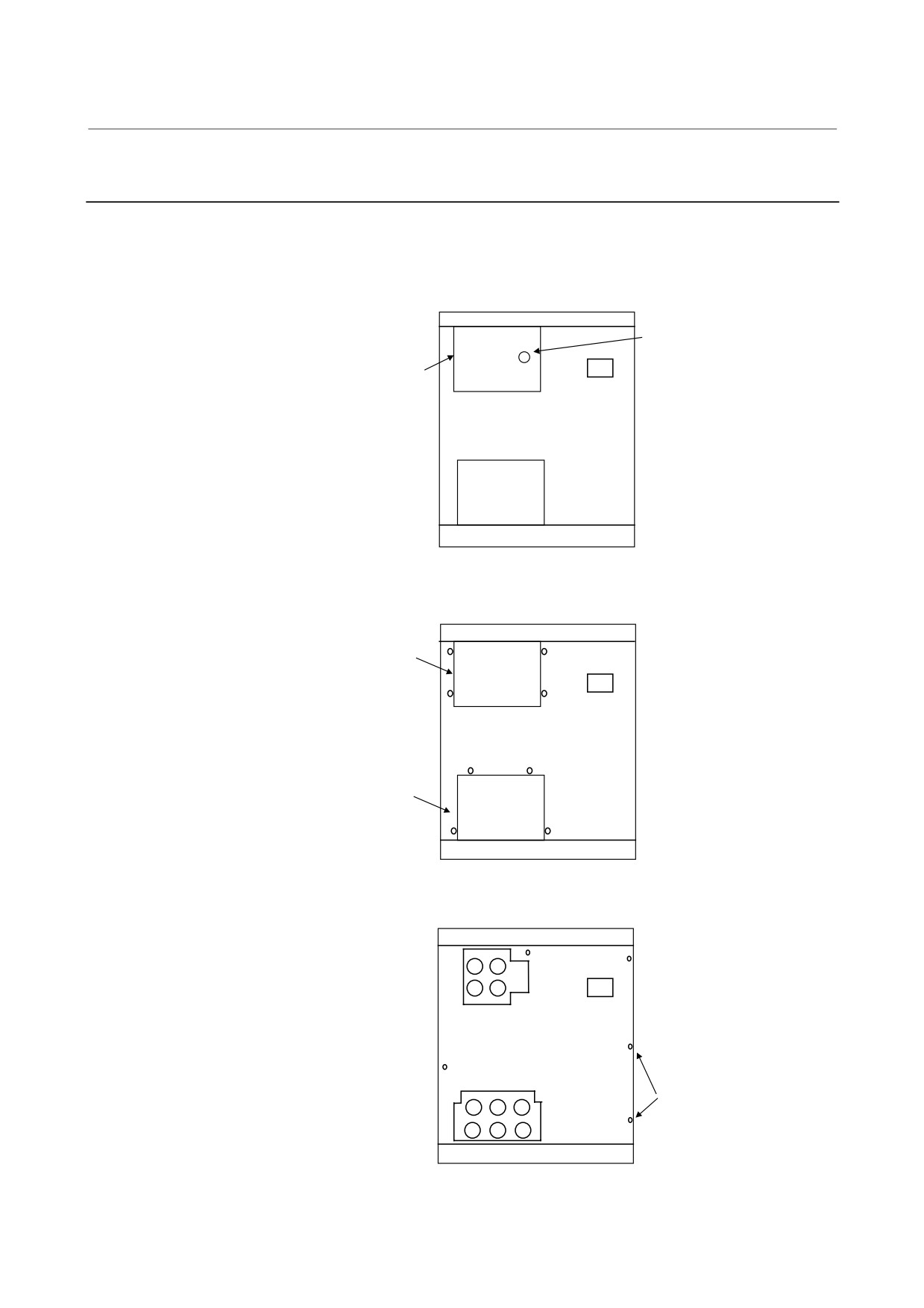
Remove the DC link cover and motor power line cover.
DC link
cover
Remove the self-tapping
screws (8 × M4) from
the DC link cover and
motor power line cover.
Motor power
line cover
Remove the face plate.
Remove the screws (5 × M4)
from the face plate.
Screw (× 5)
- 190 -
4. HOW TO REPLACE THE FUSES
B-65165E/02
TROUBLESHOOTING
AND PRINTED CIRCUIT BOARDS
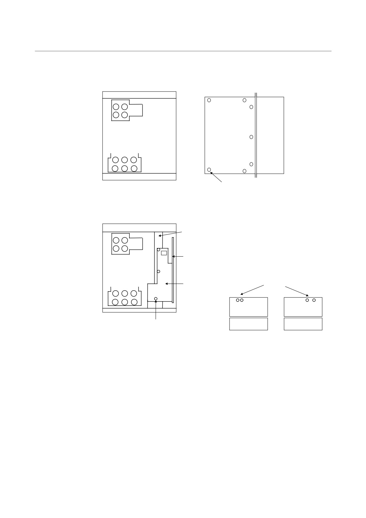
Remove the right side plate.
Remove the
screws (7 × M4)
from the right side
Plate
plate.
Heat sink
Screw (7 × M4)
Remove the connector module and plate.
<1> Remove the screws (3 × M3) from the
connector module.
Plate
<2> Pull the connector module out of the
control printed circuit board.
<3> Remove the screws (4 × M4) from the
plate, and remove the plate.
Control printed
circuit board
Screw (4 × M4)
Connector module
Upper side plate
Bottom plate
Screw (3 × M3)
Heat sink
Heat sink
- 191 -
4. HOW TO REPLACE THE FUSES
AND PRINTED CIRCUIT BOARDS
TROUBLESHOOTING
B-65165E/02
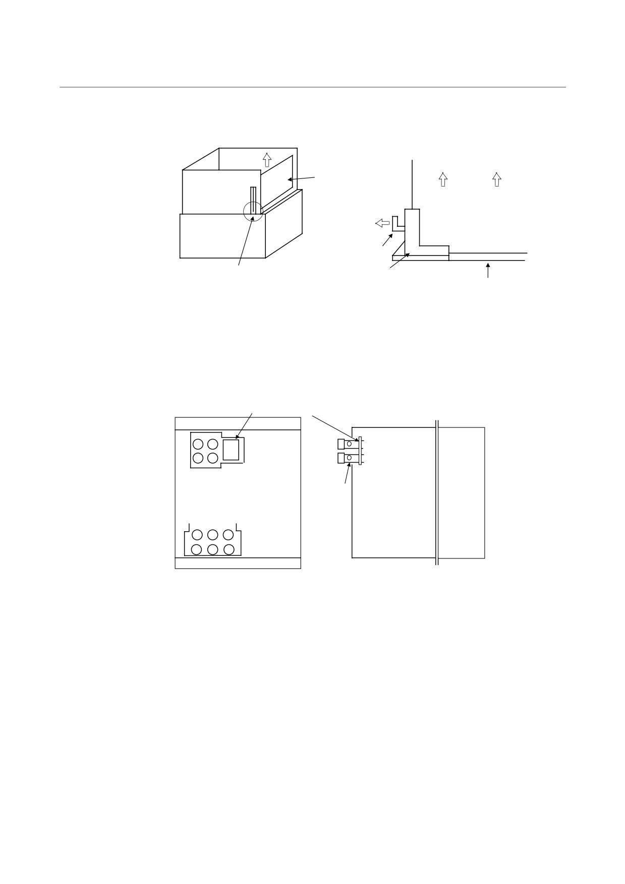
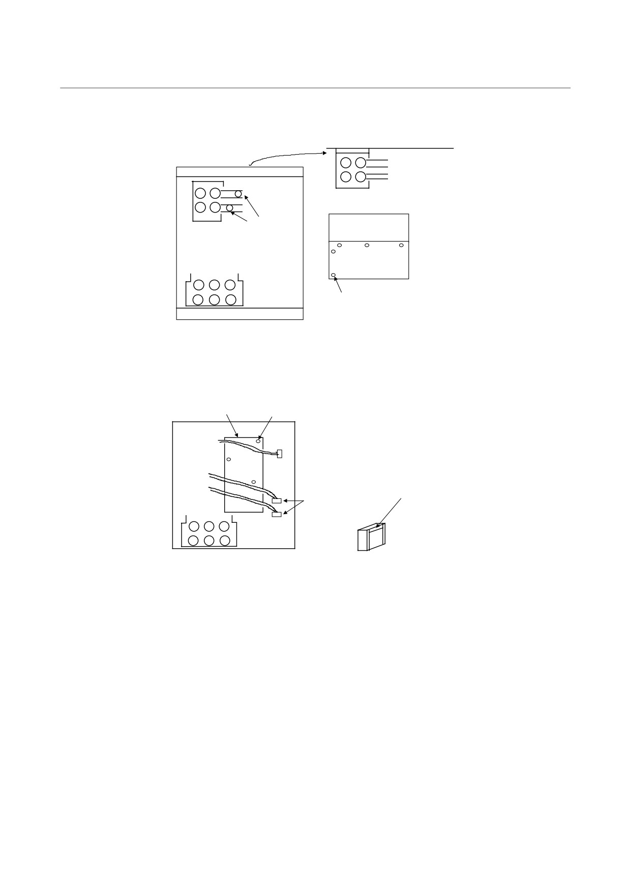
Remove the control printed circuit board.
Control printed
circuit board
Bottom plate
Control printed circuit
board
Heat sink
Hook
PCB support
PCB support
Wiring board
Insert the tip of a screwdriver into the opening on the bottom
plate, and while spreading the hook of the PCB support, pull the
printed circuit board off the flange surface toward you.
Remove the LED board for the recharge indicator.
LED board for the recharge indicator
Remove the
screws (2 × M4)
from the LED
board, and remove
the board.
Heat sink
Screw (x 2)
- 192 -
4. HOW TO REPLACE THE FUSES
B-65165E/02
TROUBLESHOOTING
AND PRINTED CIRCUIT BOARDS
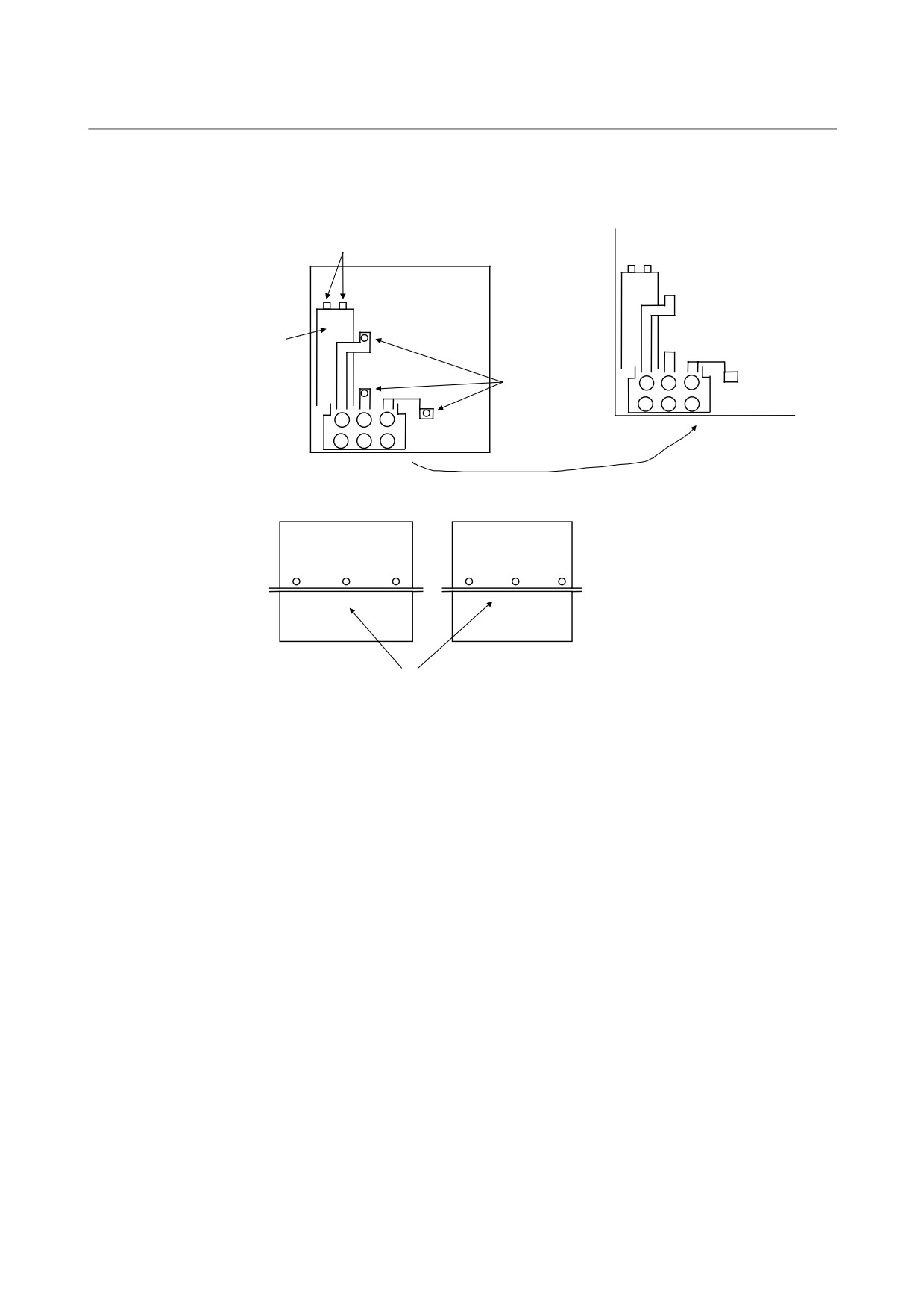
Remove the top plate.
<1> Remove the screws (2 × M5)
from the DC link jumper.
<2> Remove the screws (5 × M4)
Screw (2 × M5)
Heat sink
from the top plate.
<3> Remove the top plate. (The top
plate comes off together with
the terminal block TB1.)
Top plate
Screw (5 × M4)
Remove the driver printed circuit board.
<1> From the two connectors,
detach the cables of the current
Driver printed circuit board
sensor.
Screw × 3
<2> Remove the screws (3 × M4)
from the driver printed circuit
board.
<3> Pull up the driver printed circuit
board to remove it.
Carefully insert the tip of a screwdriver
and pull out the cable.
(Be careful not
to force the screwdriver into the
Connector × 2
connector; otherwise, the claw may
break.)
- 193 -
4. HOW TO REPLACE THE FUSES
AND PRINTED CIRCUIT BOARDS
TROUBLESHOOTING
B-65165E/02
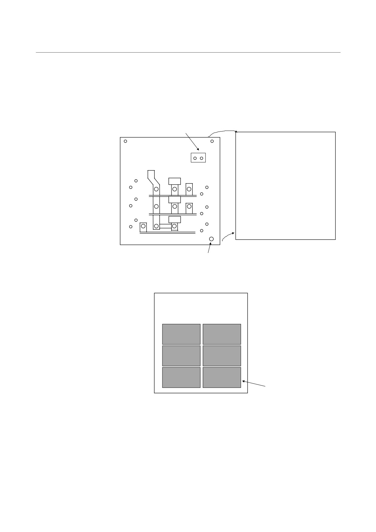
Remove the left side and bottom plates.
Screw (2 × M5)
Wiring board
Electrolytic
capacitor
Screw (3 × M6)
<1> Locate the jumpers that connect the
terminal block TB2 and the wiring
board. Remove the screws (3 × M6)
holding the jumpers to the wiring
Left side plate
Bottom plate
board.
<2> Remove the screws (2 × M5) that
connect the capacitor and jumpers.
<3> Remove the screws (6 × M4) from
the left and bottom plates.
<4> Remove the left and bottom plates.
(These plates come off together with
the electrolytic capacitor and
terminal block TB2.)
Screw (6 × M4)
- 194 -
4. HOW TO REPLACE THE FUSES
B-65165E/02
TROUBLESHOOTING
AND PRINTED CIRCUIT BOARDS
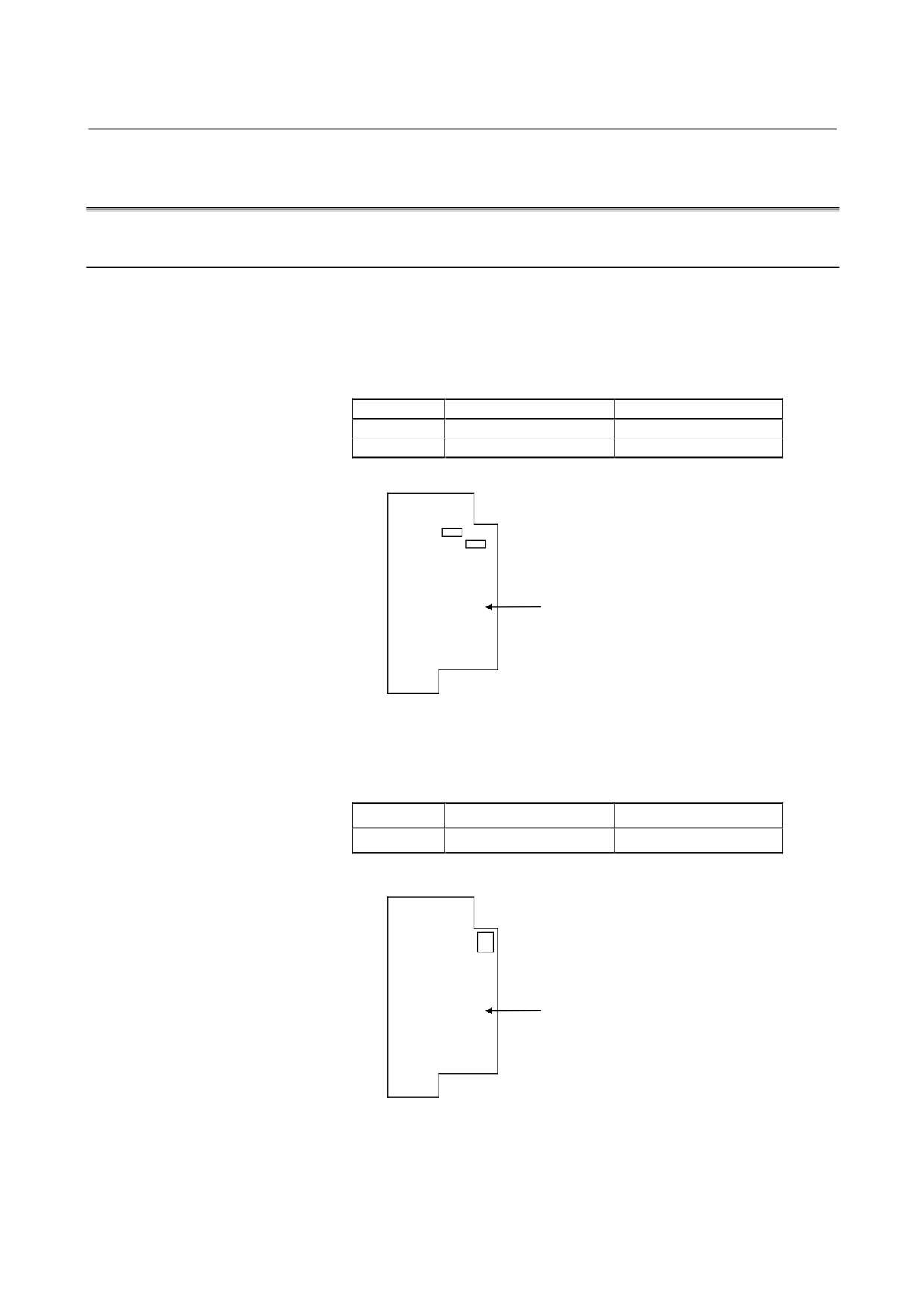
Remove the power printed circuit board.
<1> Remove the screws that connect the IGBT
and wiring board (9 × M6, 12 × M4).
<2> Remove the screws of the thermostat TH1
(2 × M4).
<3> Remove the screws that connect the wiring
board and heat sink (2 × M4, 1 × M5).
<4> Remove the wiring board.
TH1
Wiring board
FG
Remove the IGBT.
IGBT
- 195 -
4. HOW TO REPLACE THE FUSES
AND PRINTED CIRCUIT BOARDS
TROUBLESHOOTING
B-65165E/02
4.2
REPLACING FUSES
4.2.1
Power Supply Module
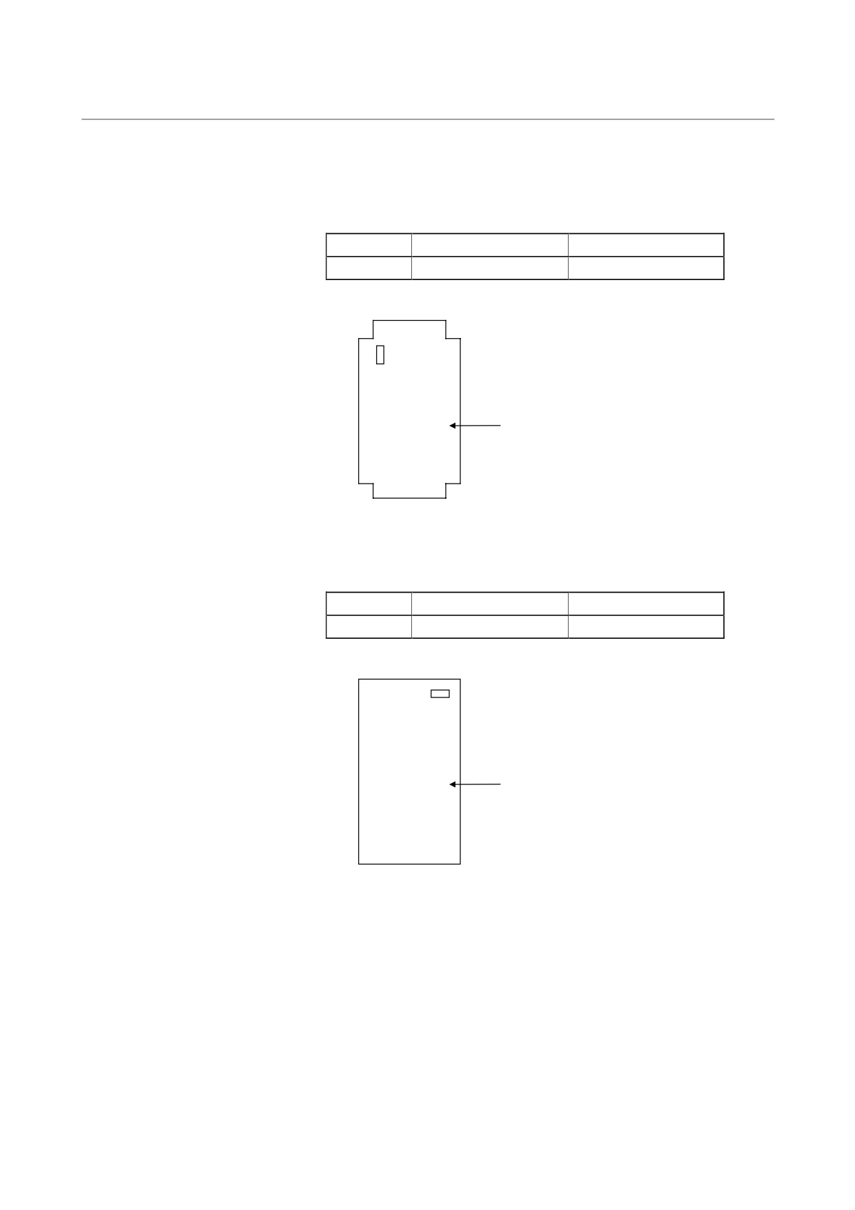
(1) Replacing fuses on the control printed circuit board
a) F1 for 200 V for the control power
b) F2 for 200 V for CX1B external cooling fan
For A16B-2202-0423 to 0424 only.
Fuse
Specification drawing No.
Remarks
F1 (FU1)
A60L-0001-0359
250V F5.0A DAITO HM50
F2 (FU2)
A60L-0001-0175#2.0A
250V F2.0A DAITO HM20
F1 (FU1)
F2 (FU2)
Control printed circuit board
(A16B-2202-0420 to 0424)
(A16B-2203-0220)
(2) Replacing a fuse on the control printed circuit board
a) F1 for 200 V for the control power
Fuse
Specification drawing No.
Remarks
F1
A60L-0001-0245#GP75
250V F7.5A DAITO GP75
F1
Control printed circuit board
(A16B-2202-0080)
- 196 -
4. HOW TO REPLACE THE FUSES
B-65165E/02
TROUBLESHOOTING
AND PRINTED CIRCUIT BOARDS
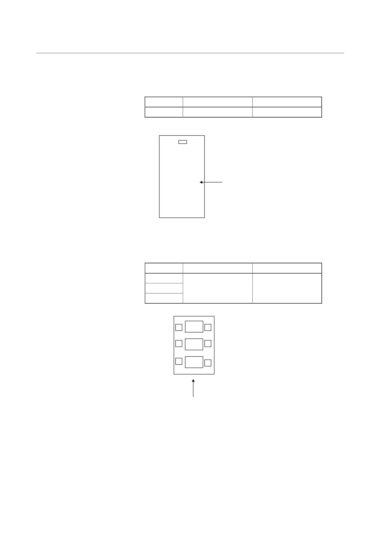
(3) Replacing a fuse on the power printed circuit board
a) F1 for the external cooling fan
Fuse
Specification drawing No.
Remarks
F1
A60L-0001-0175#0.5A
250V F0.5A DAITO HM05
F1
Power printed circuit board
(A20B-1005-0590 to 0592)
(4) Replacing a fuse on the control printed circuit board
a) F1 for 200 V for the control power
Fuse
Specification drawing No.
Remarks
F1
A60L-0001-0175#5.0A
250V F5.0A DAITO HM50
F1
Control printed circuit board
(A16B-2201-0890)
- 197 -
4. HOW TO REPLACE THE FUSES
AND PRINTED CIRCUIT BOARDS
TROUBLESHOOTING
B-65165E/02
(5) Replacing a fuse on the power printed circuit board
a) F1 for 200 V for the external cooling fan
Fuse
Specification drawing No.
Remarks
F1
A60L-0001-0359
250V F5.0A DAITO HM50
F1
Control printed circuit board
(A16B-2300-0100)
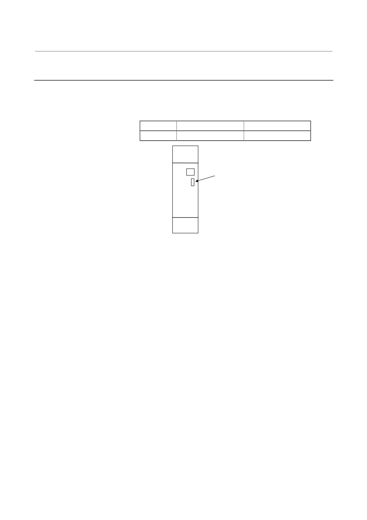
(6) Replacing fuses on the AC reactor
a) F1 to F3 for main circuit protection
Fuse
Specification drawing No.
Remarks
F1
F2
A60L-0001-0362#100U
CR6L-100/UL
F3
L11
F1
400R
L21
F2
400S
L31
F3
400T
AC reactor (A81L-0001-0144)
- 198 -
4. HOW TO REPLACE THE FUSES
B-65165E/02
TROUBLESHOOTING
AND PRINTED CIRCUIT BOARDS
4.2.2
Servo Amplifier Module
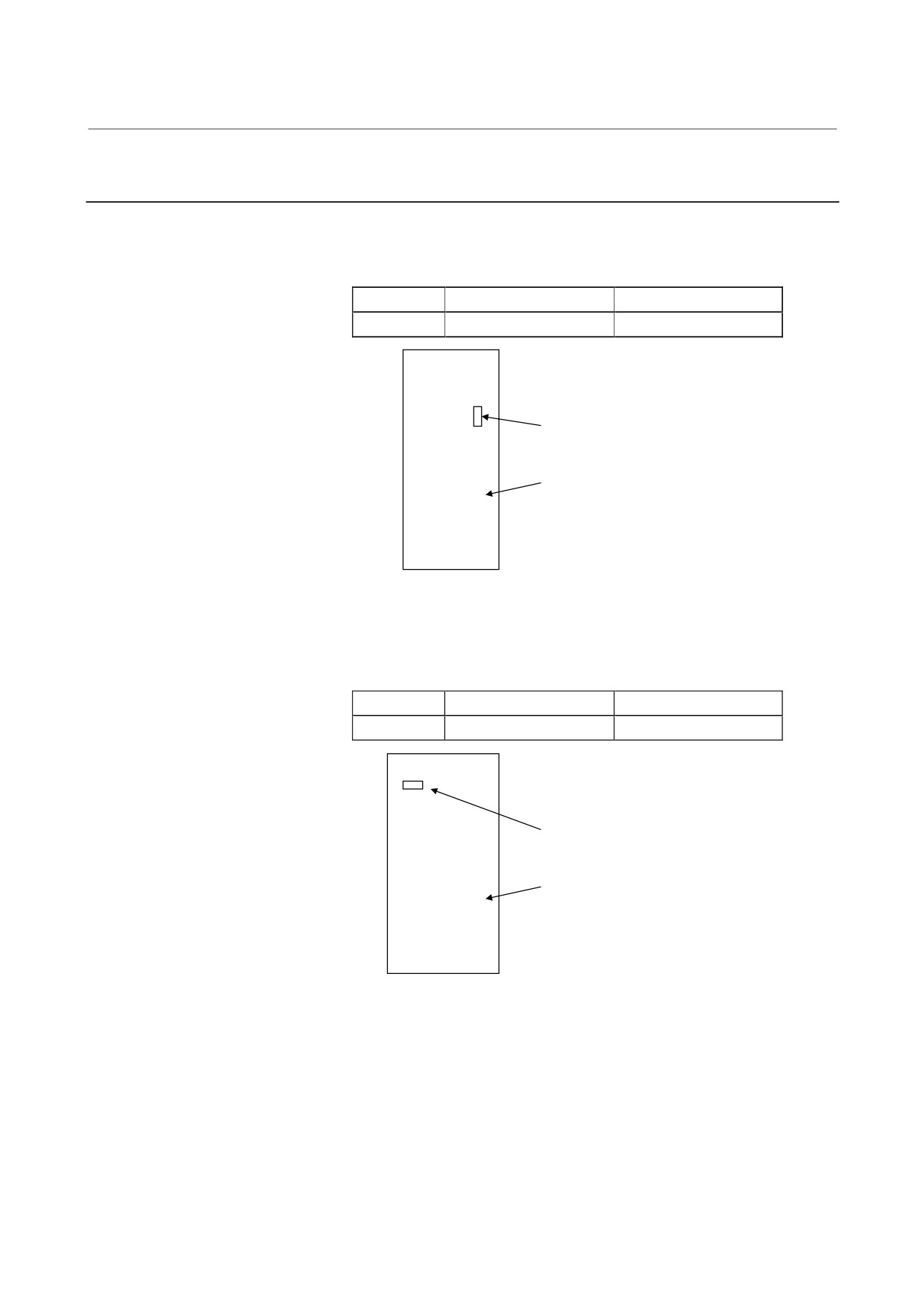
(1) Replacing a fuse on the unit (control printed circuit board)
a) F1 for the 24-V control power
Fuse
Specification drawing No.
Remarks
F1
A60L-0001-0290#LM32C
48V F3.2A DAITO LM32C
F1
- 199 -
4. HOW TO REPLACE THE FUSES
AND PRINTED CIRCUIT BOARDS
TROUBLESHOOTING
B-65165E/02
4.2.3
Spindle Amplifier Module
(1) Replacing a fuse on the control printed circuit board
a) F1 for the 24-V control power
Fuse
Specification drawing No.
Remarks
F2
A60L-0001-0290#LM32C
48V F3.2A DAITO LM32C
F1
Control printed circuit board
(A16B-2203-050x)
(2) Replacing a fuse on the power printed circuit board
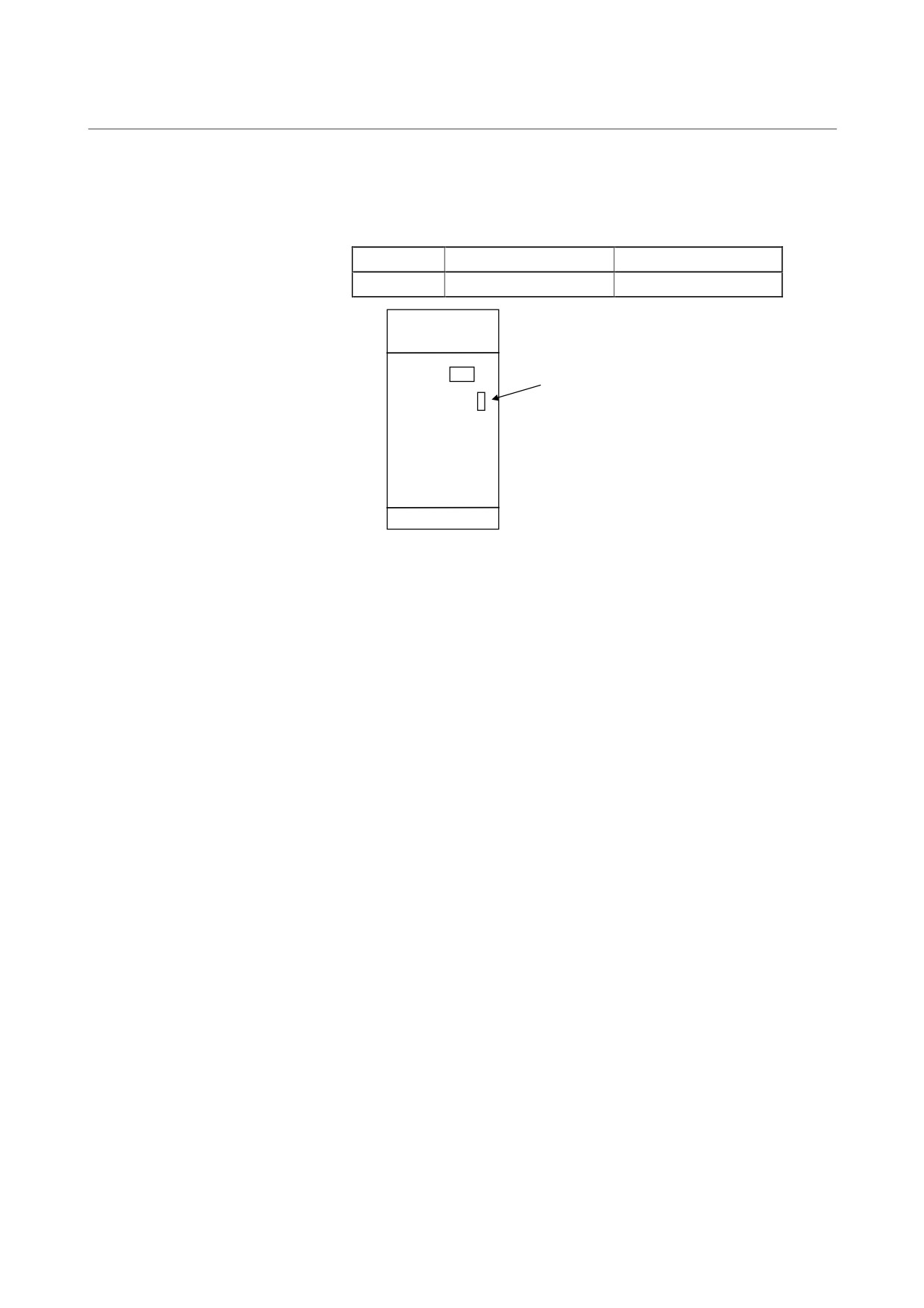
a) F2 for 200 V for the external cooling fan
Fuse
Specification drawing No.
Remarks
F2
A60L-0001-0175#0.5A
250V F5.0A DAITO HM50
F2
Wiring board
(A20B-1005-057x,
A20B-1006-048x, -055x, -0890)
- 200 -
4. HOW TO REPLACE THE FUSES
B-65165E/02
TROUBLESHOOTING
AND PRINTED CIRCUIT BOARDS
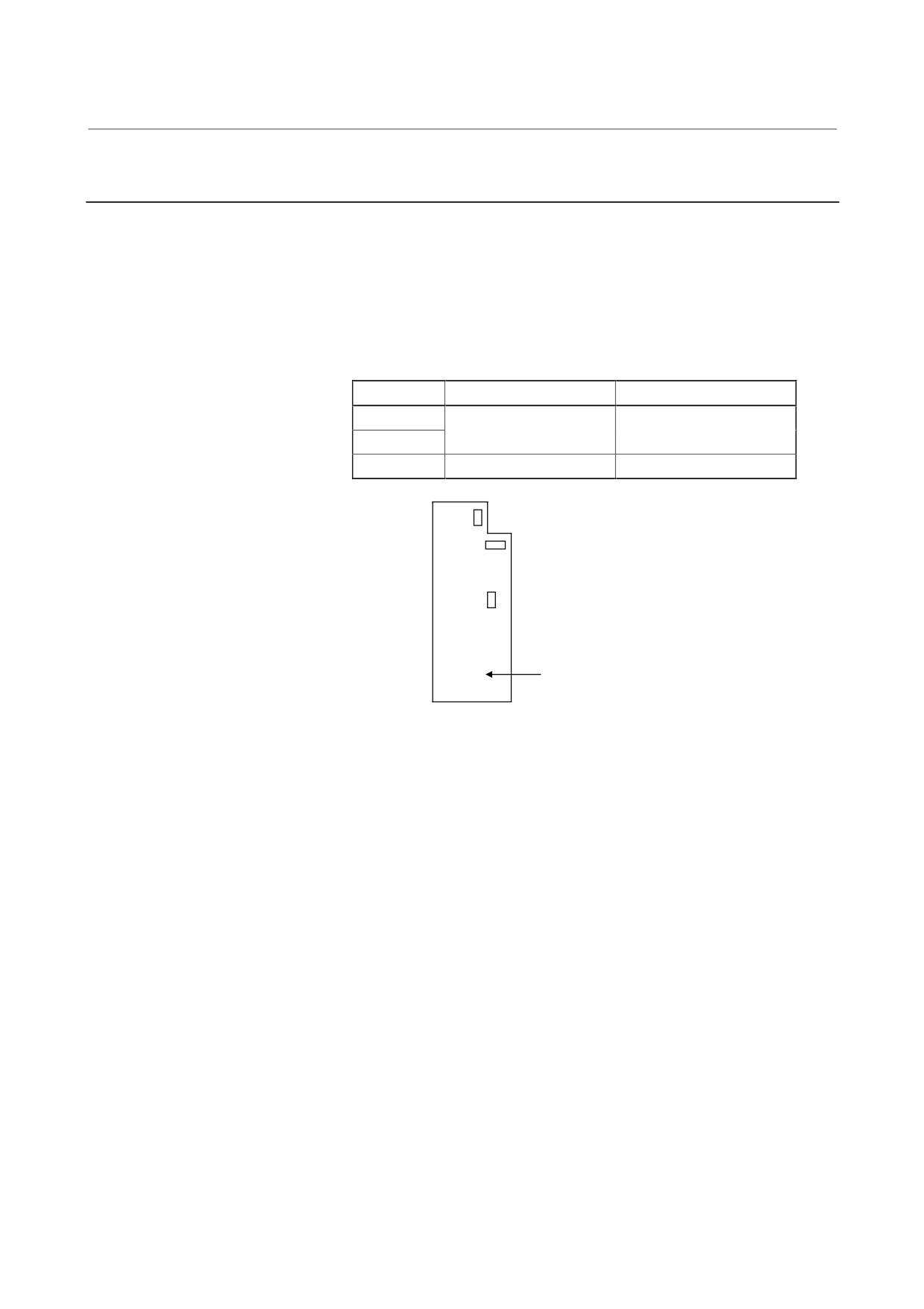
(3) Replacing a fuse on the unit (control printed circuit board)
a) F2 for the 24-V control power
Fuse
Specification drawing No.
Remarks
F2
A60L-0001-0290#LM50C
50V F5.0A DAITO LM50C
F2
- 201 -
4. HOW TO REPLACE THE FUSES
AND PRINTED CIRCUIT BOARDS
TROUBLESHOOTING
B-65165E/02
4.2.4
Power-Failure Backup Module
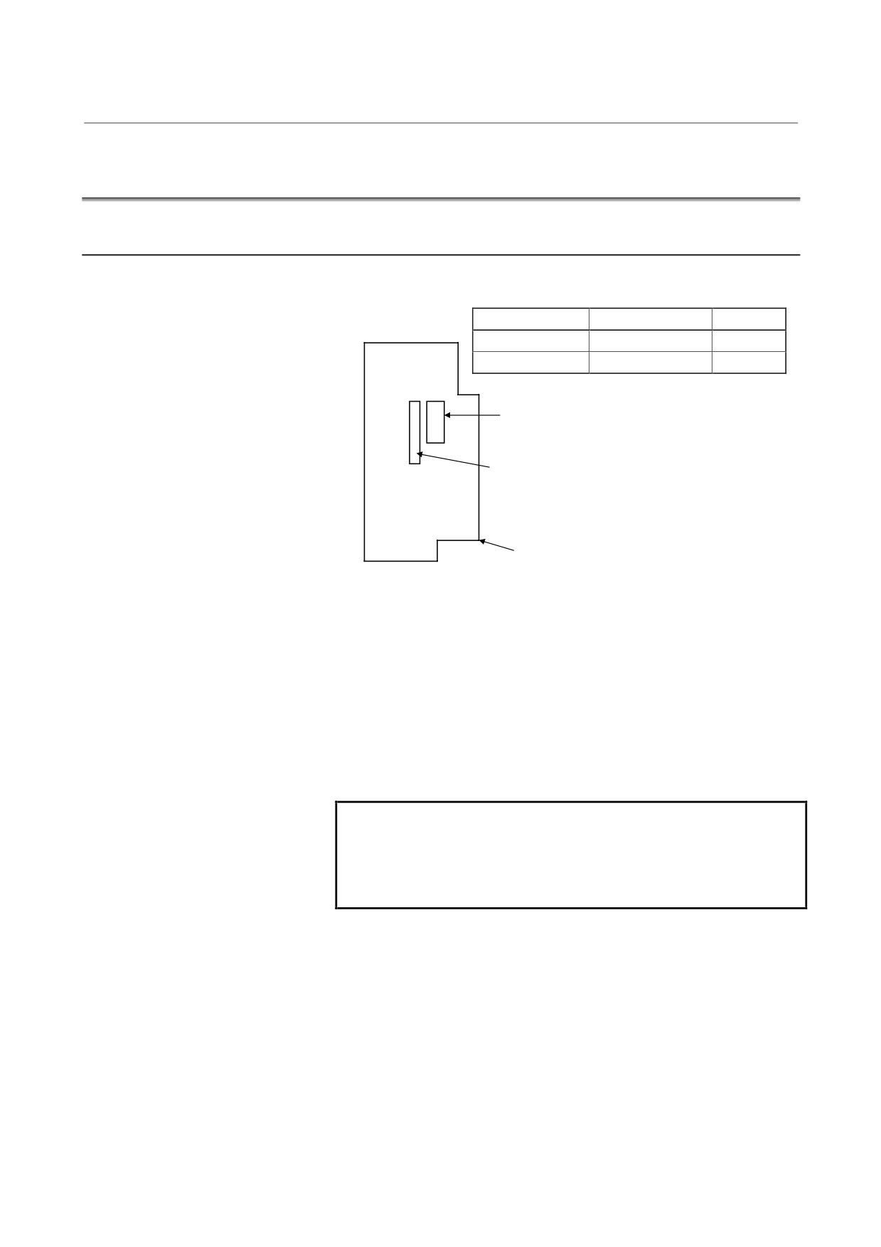
(1) Replacing fuses on the unit (control printed circuit board)
a) FU1 for 200 V for the control power
b) FU2 for 200 V for the control power
Fuses a) and b) above are provided for A16B-2203-0020
only.
c) FU3 for the 24-V control power
Fuse
Specification drawing No.
Remarks
FU1
A60L-0001-0396#10A
216-010 (ECX)
FU2
FU3
A60L-0001-0290#LM32C
48V F3.2A DAITO LM32
FU1
FU2
FU3
Control printed circuit board
(A16B-2002-0790, A16B-2003-0020)
- 202 -
4. HOW TO REPLACE THE FUSES
B-65165E/02
TROUBLESHOOTING
AND PRINTED CIRCUIT BOARDS
4.3
OTHER COMPONENTS
4.3.1
Replacing the SPM Program ROM and Spindle Sensor Module
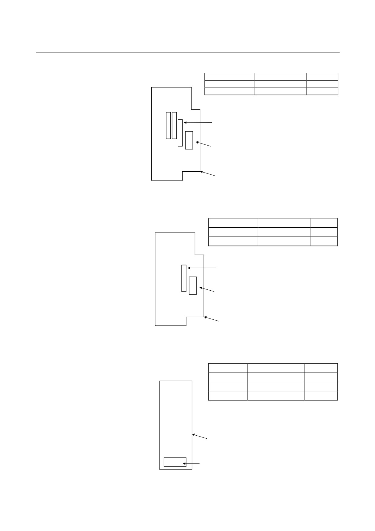
(1) SPM type 1 and type 4
Name
Specification drawing No.
Remarks
ROM
A06B-6102-H520
9D20 series
Spindle sensor module
A20B-2902-0620
For type 4 only
D4
ROM (Note that the notch is upward.)
Spindle sensor module: For A16B-2203-0503-0505 only
AM1
Control printed circuit board
(A16B-2203-0500-0505)
(2) SPM types 1 to 4
The drawing number of the spindle sensor module differs
depending on the SPM type as follows:
SPM type 2: A20B-2901-0851
Mounting location = MD4, MD5, MD6
SPM type 4: A20B-2902-0620 (old specification A20B-2902-
0610 also allowed)
Mounting location = MD4, MD6
NOTE
For SPM type 4, the revision of the control printed
circuit board must be the following:
A16B-2202-0433, 0434: 16E or later
A16B-2202-0435: 13C or later
- 203 -
4. HOW TO REPLACE THE FUSES
AND PRINTED CIRCUIT BOARDS
TROUBLESHOOTING
B-65165E/02
Name
Specification drawing No.
Remarks
ROM
A06B-6072-H500
9D0A series
Spindle sensor module
See the above table.
MD4, 5, 6
MD4
MD6
Spindle sensor module × 3
MD5
ROM
MG11
Control printed circuit board
(A16B-2202-0430 to 0435, A16B-2203-0330 to 0332)
(3) SPM type 3
Name
Specification drawing No.
Remarks
ROM
A06B-6072-H500
9D0A series
Spindle sensor module
A20B-2901-0851
MD4
Spindle sensor module
ROM
MG11
Control printed circuit board (A06B-2202-0440)
(4) SPMC-2.2 to 11
Name
Specification drawing No.
Remarks
ROM
A06B-6082-H512
9D12 series
ROM
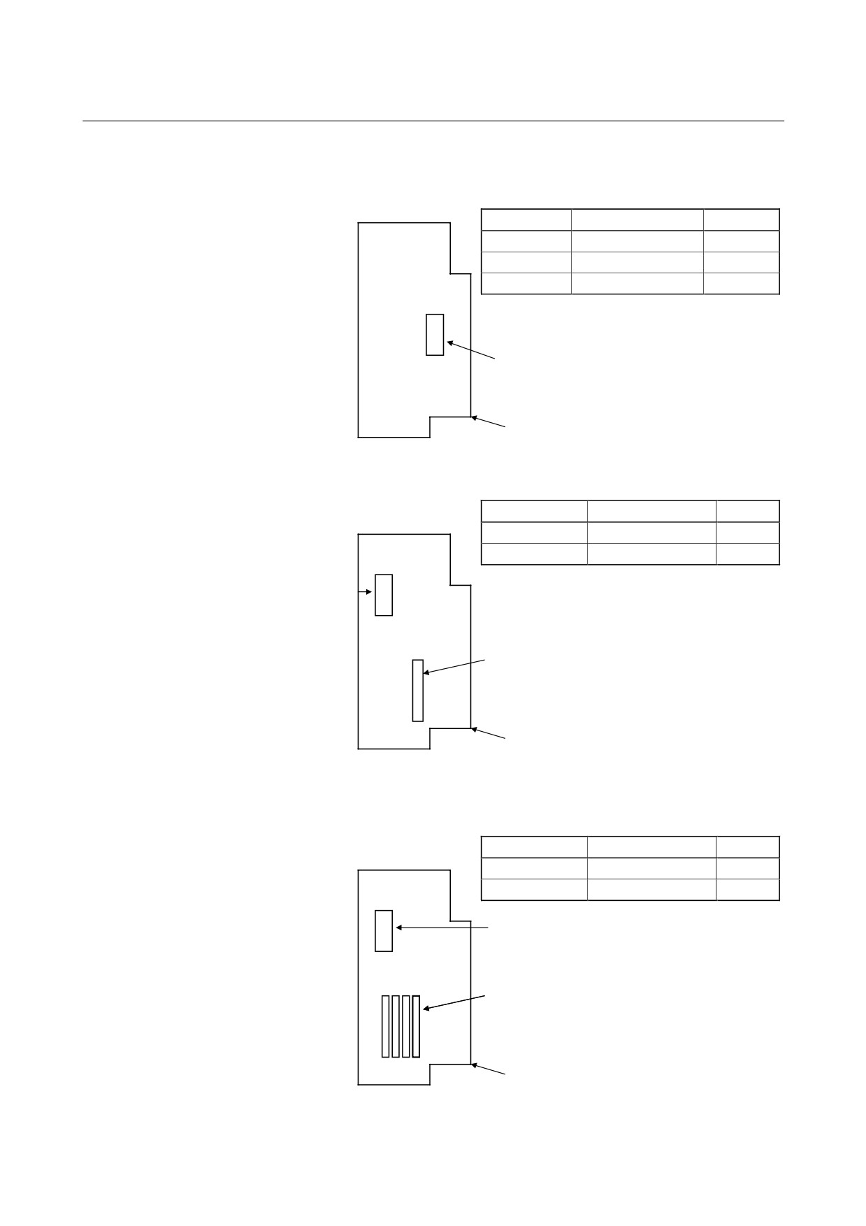
A06B-6082-H511
9D11 series
ROM
A06B-6082-H510
9D10 series
Control printed circuit board
(A20B-2001-0780, 0781)
MC8
ROM
- 204 -
4. HOW TO REPLACE THE FUSES
B-65165E/02
TROUBLESHOOTING
AND PRINTED CIRCUIT BOARDS
(5) SPMC-15 to 26
Name
Specification drawing No.
Remarks
ROM
A06B-6082-H512
9D12 series
ROM
A06B-6082-H511
9D11 series
ROM
A06B-6082-H511
9D10 series
D8
ROM
Control printed circuit board (A06B-2202-0840)
(6) SPM type 1 of old specification
Name
Specification drawing No.
Remarks
ROM
A06B-6072-H500
9D0A series
Spindle sensor module
A20B-2901-0851
MF4
ROM
MD3
Spindle sensor module × 1
Control printed circuit board (A06B-2202-0070)
(7) SPM types 2 and 3 of old specification
Name
Specification drawing No.
Remarks
ROM
A06B-6072-H500
9D0A series
Spindle sensor module
A20B-2901-0851
MF4
ROM
MD6
MD3
Spindle sensor module × 4
Control printed circuit board (A06B-2202-0160)
- 205 -
III. MOTOR MAINTENANCE
1. AC SERVO MOTOR
B-65165E/02
MOTOR MAINTENANCE
MAINTENANCE
1
AC SERVO MOTOR MAINTENANCE
Generally, AC servo motors have no parts that wear off or that must be
replaced periodically, unlike DC servo motors, which have brushes that
must be replaced periodically.
However, you should perform periodic maintenance for servo motors
so as to keep their initial performance as long as possible and to prevent
breakdowns. AC servo motors have precision detectors. Their
incorrect use or damage caused during transportation or assembling can
result in breakdowns or accidents. We recommend that you inspect the
servo motors periodically according to the descriptions given below.
- 209 -
1. AC SERVO MOTOR
MAINTENANCE
TROUBLESHOOTING
B-65165E/02
1.1
RECEIVING AND KEEPING AC SERVO MOTORS
When you receive an AC servo motor, make sure that:
• The motor is exactly the one you ordered, in terms of model, shaft,
and detector specifications.
• No damage has been caused on the motor.
Because FANUC inspects servo motors strictly before shipment, you
do not, in principle, have to inspect them when you receive them.
However, you should check the specifications (wiring, current, and
voltage) of the motor and detector carefully, as required.
The servo motors should be kept indoors as a rule. The storage
temperature range is -20 to +60°C. Do not place or install AC servo
motors in the place where:
• It is extremely humid and dew is prone to form,
• There is a steep change in temperature,
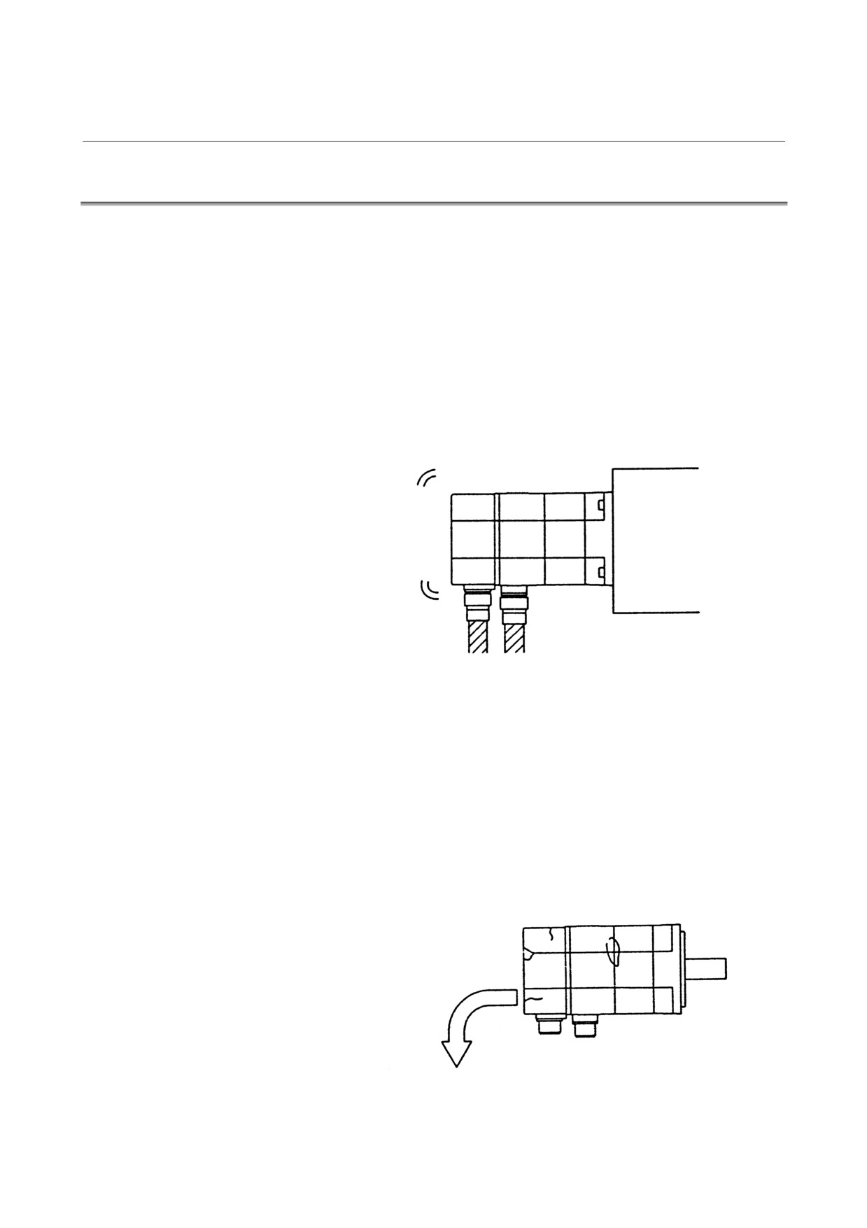
• There is constant vibration, which may cause damage to the shaft
bearings, or
• There is lots of dust and trash.
- 210 -
1. AC SERVO MOTOR
B-65165E/02
MOTOR MAINTENANCE
MAINTENANCE
1.2
DAILY INSPECTION OF AC SERVO MOTORS
Before starting operation, or periodically (once a week or month), you
should inspect the AC servo motors in terms of the following:
(1) Vibration and noise
Check the motor for abnormal vibration (by the hand) and noise
(by the ear) when the motor is:
• Not rotating
• Rotating at low speed
• Accelerating or decelerating
If you find anything unusual, contact your FANUC service staff.
(2) Damage on the outside
Check the motor cover (red plastic) for crevices and the motor
surface (black coating) for scratches and cracks.
If you find a crevice in the motor cover, you should replace it as
quickly as possible. For how to replace, see the description about
the pulse coder in Section
1.4. If you are not sure about
replacement, contact you FANUC service staff.
If there is a scratch or crack on the motor surface, the user should
repair it by himself as required. If coating has come off, dry the
portion of interest (or the entire surface) and coat it with paint for
machines such as urethane paint.
Replace a motor cover with a crevice or crack
as quickly as possible.
- 211 -
1. AC SERVO MOTOR
MAINTENANCE
TROUBLESHOOTING
B-65165E/02
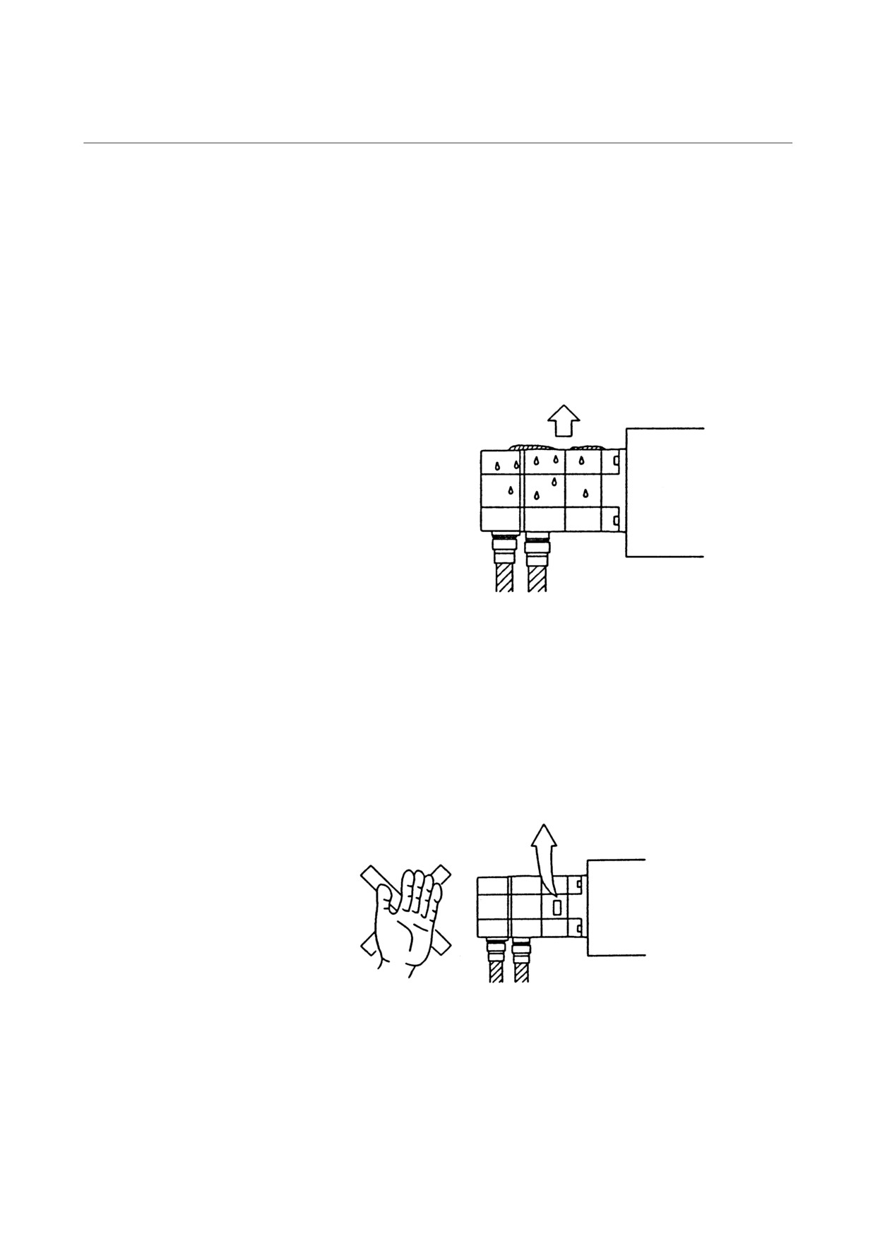
(3) Stains and smudges
Check the motor surface and bolt holes for oil or cutting fluid.
Wipe off oil and cutting fluid on the motor surface periodically.
Oil or cutting fluid can damage the coating by chemical reaction,
possibly leading to a failure.
Also check how such a liquid leaks onto the motor, and repair if
needed.
Wipe off oil and cutting fluid on the motor
surface periodically.
(4) Overheating
Check to see if the motor is too hot during normal operation.
Attach a thermolabel on the motor surface and check it visually to
see if the motor becomes too hot during normal operation.
Note) Temperature on the motor surface can exceed 80°C
under some conditions. Never touch it by the hand.
Attach a thermolabel and
check it visually.
- 212 -
1. AC SERVO MOTOR
B-65165E/02
MOTOR MAINTENANCE
MAINTENANCE
1.3
PERIODIC INSPECTION OF AC SERVO MOTORS
We recommend that you inspect the AC servo motors for the following
items at least once a year.
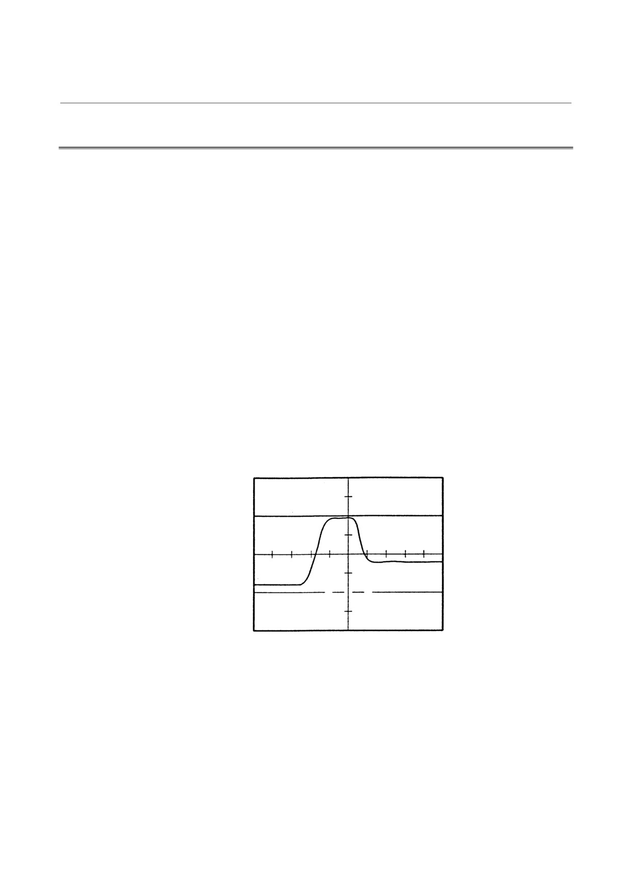
(1) Observation of torque command (TCMD) and speed command
(VCMD) waveforms
Observe normal voltage waveforms with an oscilloscope, and
keep notes of them. During periodic inspection, check the current
waveforms with the records.
The waveforms vary according to the operating conditions such as
load and cutting speed. Note that you should make comparisons
under the same condition (for example, during fast traverse to the
reference position or low-speed cutting).
See descriptions on the check boards in I-4.2.5 for detailed
inspection procedures.
(2) Diagnosis by waveforms
Check the measured waveforms to see whether:
<1> The peak current is within the limit to the current in the
amplifier.
The limit to the amplifier current is listed below.
Limit to the amplifier
current
Measured waveform
0
⇒ The motor used to accelerate/decelerate with the amplifier
current within the limit (the acceleration/deceleration torque
used to be sufficient), but something is wrong now. If this is
the case, the probable causes are:
• The load conditions in the machine have changed because
of changed friction or reduced machine efficiency after
long period of use.
• Motor failure
- 213 -
1. AC SERVO MOTOR
MAINTENANCE
TROUBLESHOOTING
B-65165E/02
Increased friction
Reduced efficiency
[Table 1]
Current
Models
value
α1/3000, α2/2000, α2/3000
12Ap
αM2/3000, αM2.5/3000, αC3/2000, αC6/2000, αC12/2000,
20Ap
α3/3000HV, α6/3000HV
α3/3000, α6/2000, α12/2000, α22/1500, αC22/1500,
40Ap
α12/3000HV, αM6/3000HV, αM9/3000HV
α22/3000HV, α30/3000HV, αM22/3000HV, αM30/3000HV
60Ap
α6/3000, α12/3000, α22/2000, α30/1200, αM6/3000, αM9/3000,
80Ap
αL6/3000, αL9/3000
α22/3000, α30/2000, α30/3000, α40/2000, α40/2000 (with fan),
130Ap
αM22/3000, αM30/3000, αM40/3000, αL25/3000, αL50/2000
α65/2000
240Ap
αM40/3000 (with fan), α100/2000, α150/2000
360Ap
α300/2000, α400/2000
360Ap × 2
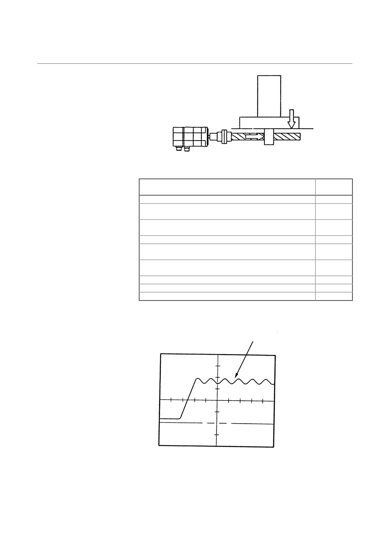
<2> The waveform has ripple during constant-speed feeding.
Ripple
Measured waveform
0
- 214 -
1. AC SERVO MOTOR
B-65165E/02
MOTOR MAINTENANCE
MAINTENANCE
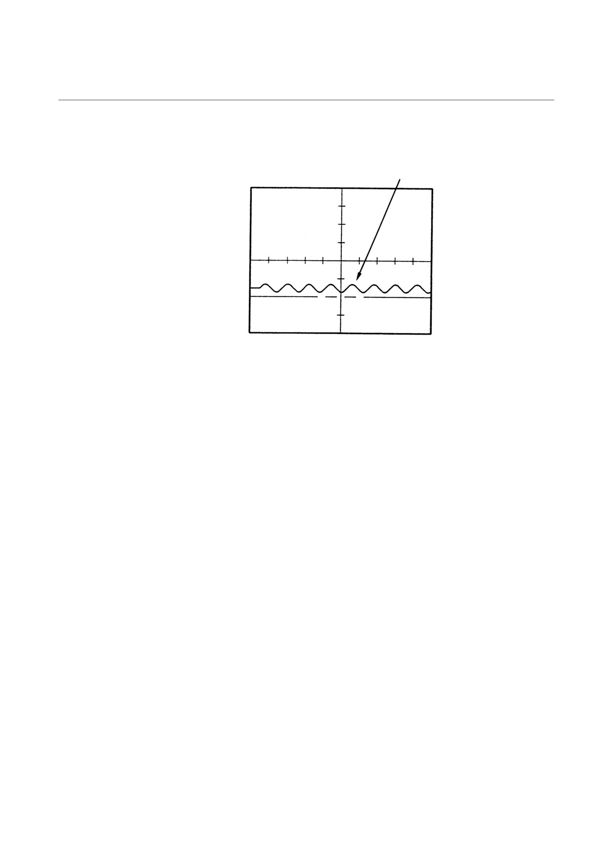
<3> The current waveform has ripple or jumps when the motor is
not rotating.
Ripple
Measured waveform
0
If you find anything unusual in relation to the above items, contact
your FANUC service staff.
- 215 -
1. AC SERVO MOTOR
MAINTENANCE
TROUBLESHOOTING
B-65165E/02
1.4
REPLACING THE PULSE CODER
This section explains how to replace the pulse coder and motor cover,
assuming that the pulse coder has broken down and is in need of
immediate replacement.
When replacing the pulse coder and motor cover, be careful not to give
a shock to the pulse coder or motor, because they are precision devices
prone to a breakdown. Also keep them from dust and cutting chips.
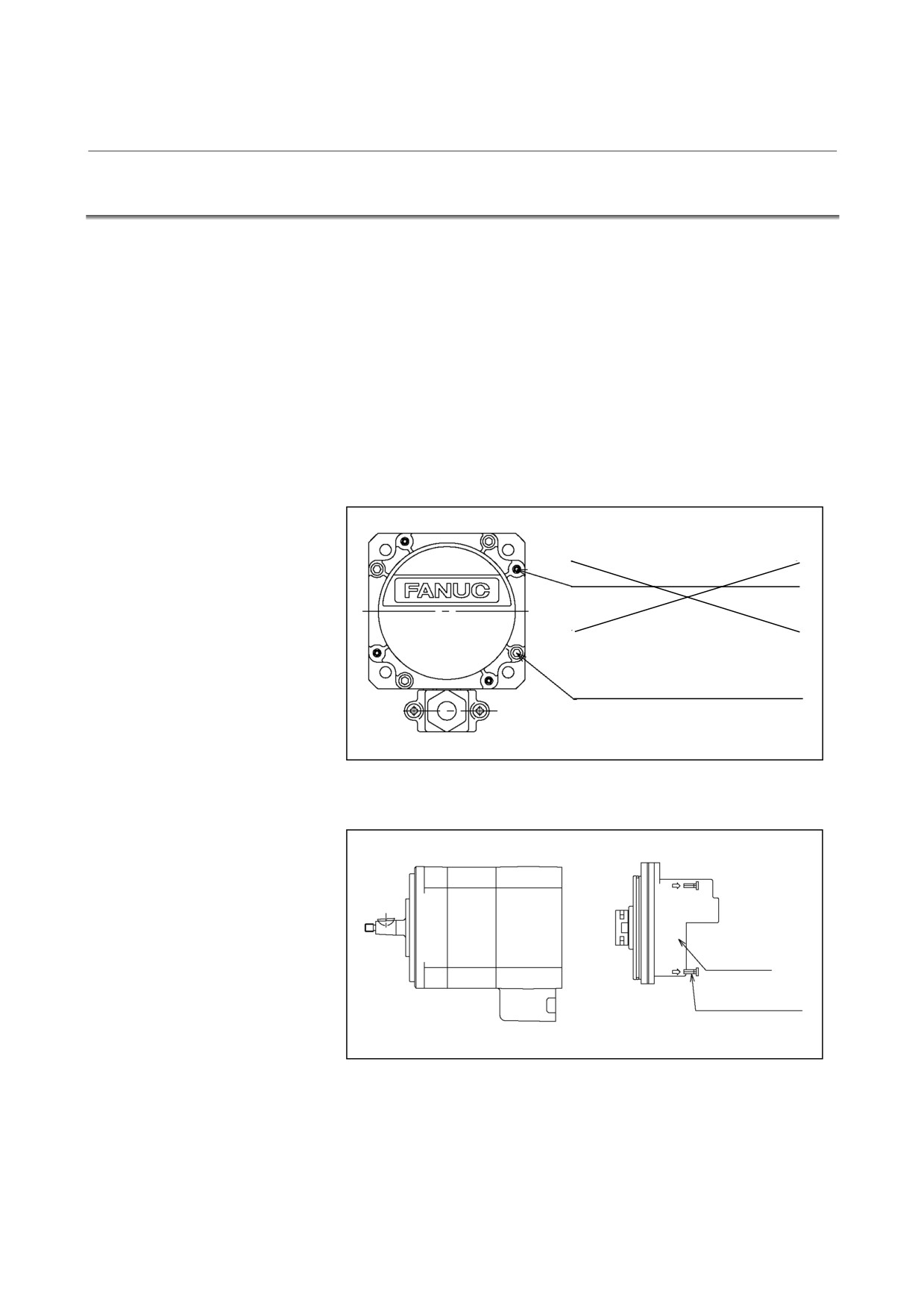
(1) Models α1, α2, αM2, αM2.5
<1> Remove the four M4 hexagonal socket head bolts that fasten
the pulse coder. Do not loosen the M3 bolts near each M4
bolt.
(Removing the M3 bolts will impair airtightness.)
Pulse coder cver fastening bolts M3
PULSECODER COVER
FASTENING SCREWS M3
Pulse coder fastening bolts M4 × 16
PULSECODER
FASTENING SCREWS M4 × 16
<2> Remove the pulse coder and Oldham’s coupling.
Pulse coder
Pulse coder fastening bolts
M4 × 16(4)
- 216 -
1. AC SERVO MOTOR
B-65165E/02
MOTOR MAINTENANCE
MAINTENANCE
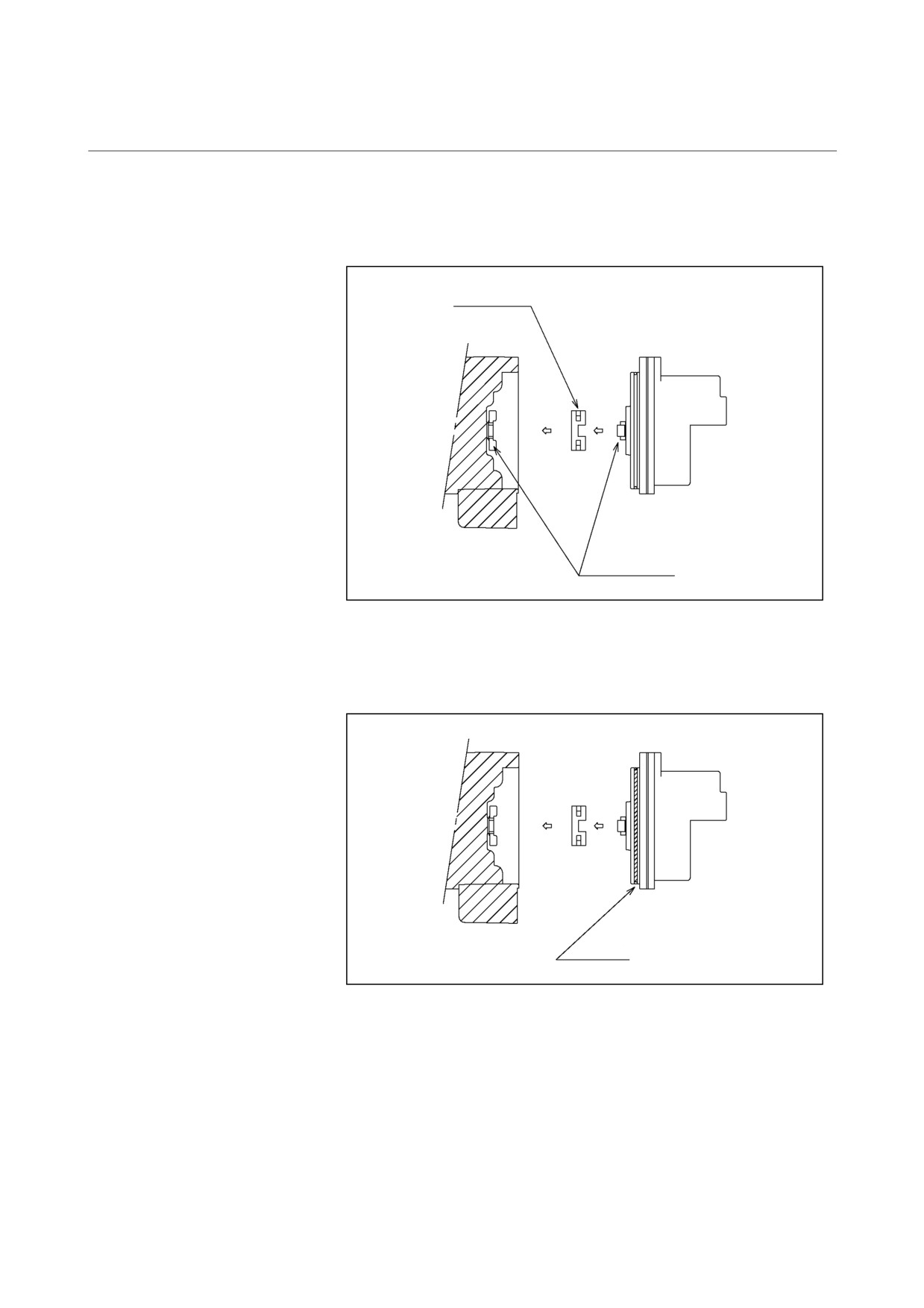
<3> Set a new pulse coder and a new Oldham’s coupling in the
motor. Place the Oldham’s coupling with the correct
orientation, and engage the teeth.
Oldham’s coupling
Mate coupling of the
Oldham’s coupling
<4> Fasten the pulse coder with the four M4 hexagonal socket
head bolts. When tightening the bolts, be careful not to catch
the O-ring mounted on the pulse coder.
O-ring
- 217 -
1. AC SERVO MOTOR
MAINTENANCE
TROUBLESHOOTING
B-65165E/02
(2) Models α3 to α40, αM6 to αM40, αL, αC, α3HV to α30HV,
αM6HV to αM30HV
<1> Loosen the bolts that retain the red motor cover to remove
the cover. Check whether the pulse coder is of the cable
separation type (the pulse coder cable can be detached from
the red cover of the pulse coder) or of the cable non-
separation type
(the cable cannot be detached from the
cover). For the replacement of a cable separation type pulse
coder, see Item <2>-1. For the replacement of a cable non-
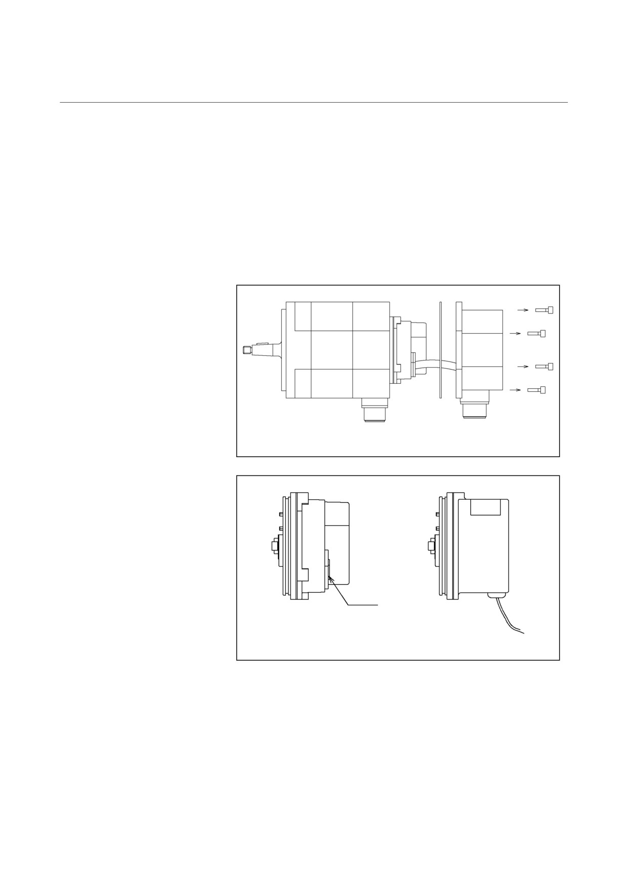
separation type pulse coder, see Item <2>-2.
Packing
Motor
Motor cover
Connector
Cable separation
Cable non-separation
type pulse coder
type pulse coder
- 218 -
1. AC SERVO MOTOR
B-65165E/02
MOTOR MAINTENANCE
MAINTENANCE
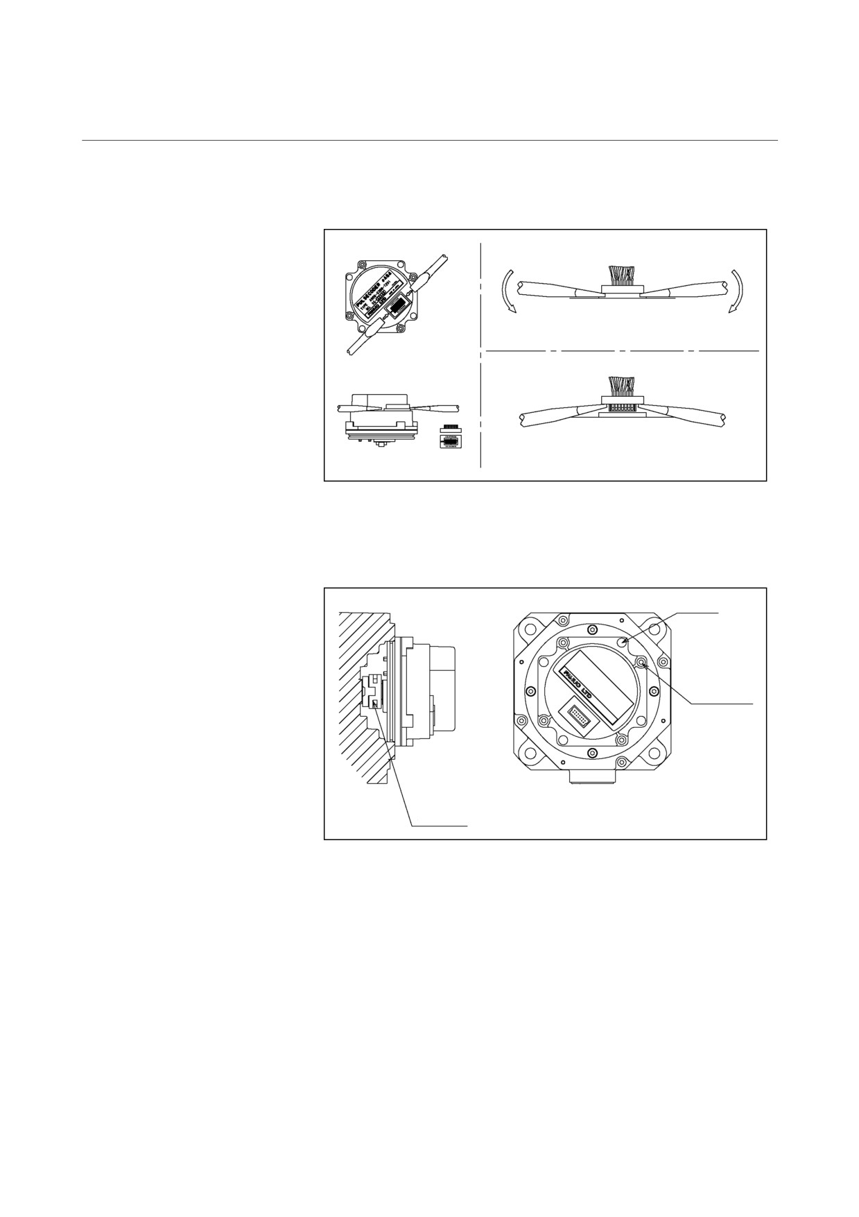
<2>-1 (Cable separation type)
(a) Remove the cable of the pulse coder by using a screwdriver.
<1>
<2>
Cover
<3>
Cover
(b) Remove the four M4 hexagonal socket head bolts that retain
the pulse coder. Do not loosen the M3 bolts that retain the
pulse coder cover.
M4 × 10
Do not loosen
these bolts.
Oldham’s
coupling
(c) Remove the pulse coder and Oldham’s coupling.
(d) Set a new pulse coder and new Oldham’s coupling in the
motor. Although the mounting orientation is not specified in
particular, it is recommended that the pulse coder be set with
the same orientation as before the replacement. This is
because of the convenience of cabling. Place the Oldham’s
coupling with the correct orientation, and engage the teeth.
(e) Fasten the pulse coder with the four M4 hexagonal socket
head bolts.
- 219 -