FANUC Alpha Series Motors and Modular Drives. Maintenance Manual (GFZ-65165E/02) - page 7
3. TROUBLESHOOTING
AND ACTION
TROUBLESHOOTING
B-65165E/02
3.4.1.20 Alarm code 30
An excessively large current is detected at the input of the 3-phase main
circuit of the PSM.
(1) If the PSM indicates alarm code 1
Troubleshoot according to the description of alarm code
1
provided in Section 3.1 of Part II.
(2) If the PSM indicates no alarm
(a) A cable is faulty.
The connection cable between the PSM (JX1B) and SPM
(JX1A) is faulty. Replace the cable.
(b) The SPM is faulty.
Replace the SPM or SPM control printed circuit board.
3.4.1.21
Alarm code 31
The motor failed to rotate as specified, and has stopped or is rotating at
a very low speed.
(1)
If the motor rotates at a very low speed and this alarm is issued
(a) The setting of a parameter is incorrect.
Referring to "FANUC AC SPINDLE MOTOR α series
Parameter Manual (B-65160E)," check the parameter for
sensor setting.
(b) The motor phase sequence is incorrect.
Check if the motor phase sequence is correct.
(c) The feedback cable of the motor has a problem.
Check if the phase A/B signals are connected correctly.
(d) The feedback cable of the motor is faulty.
Rotate the motor manually to see if a speed is indicated in the
item of motor speed on the CNC diagnosis screen or on the
spindle check board. If no speed indication is provided,
replace the cable or spindle sensor (or motor).
(2)
If the motor does not rotate at all and this alarm is issued
(a) The sequence for locking the spindle is incorrect.
Check the sequence to see if the spindle is locked.
(b) The power line is faulty.
Check if the power line is connected to the motor correctly.
If spindle switching or winding switching is performed,
check if the magnetic contactor is on.
(c) The SPM is faulty.
Replace the SPM.
- 158 -
3. TROUBLESHOOTING
B-65165E/02
TROUBLESHOOTING
AND ACTION
3.4.1.22 Alarm code 32
LSI memory for serial communication is abnormal. A check is made
when the power is turned on.
If this alarm is issued, replace the SPM or SPM control printed circuit
board.
3.4.1.23 Alarm code 33
The PSM could not be charged within a specified time.
PSM input has an open phase.
(1) If the PSM indicates alarm code 5
Troubleshoot according to the description of alarm code
5
provided in Section 3.1 of Part II.
(2) If the PSM indicates no alarm
(a) A cable is faulty.
The connection cable between the PSM (JX1B) and SPM
(JX1A) is faulty. Replace the cable.
(b) The SPM is faulty.
Replace the SPM or SPM control printed circuit board.
3.4.1.24 Alarm code 34
Parameter data outside the specifiable range was set.
Troubleshooting when this alarm is issued
Connect the spindle check board.
The spindle check board displays "AL-34" and "F-xxx"
alternately. "F-xxx" indicates a parameter number outside the
specifiable range. For the correspondence between the CNC
parameter numbers and "F-xxx," refer to "FANUC AC SPINDLE
MOTOR α series Parameter Manual (B-65160E)."
- 159 -
3. TROUBLESHOOTING
AND ACTION
TROUBLESHOOTING
B-65165E/02
3.4.1.25 Alarm code 35
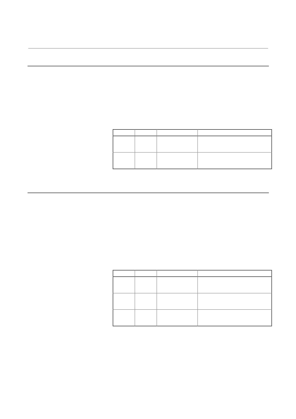
The gear ratio set in a parameter exceeds the value range allowable for
internal processing. This alarm is issued with a parameter related to
orientation of magnetic sensor type.
Troubleshooting when this alarm is issued
(a) The gear ratio set in a parameter is incorrect.
Check if an excessively large gear ratio is set.
FS0
FS15i
FS16i/16, PM-D/F
Description
6556
3056
4056
Gear ratio between the spindle and
to
to
to
motor
6559
3059
4059
6560
3060
4060
Position gain at orientation
to
to
to
6563
3063
4063
3.4.1.26
Alarm code 36
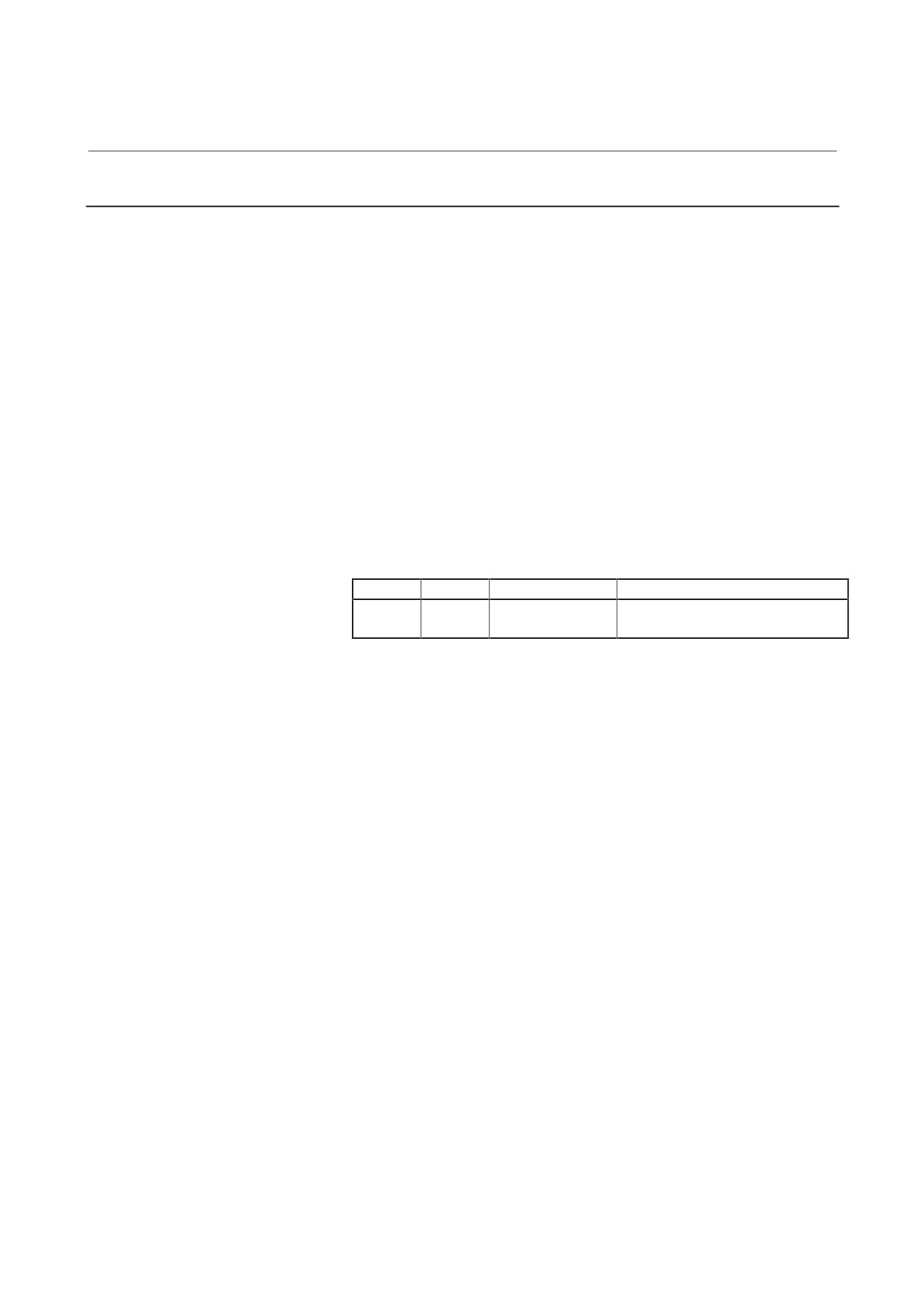
The error counter overflowed.
(1) The setting of a parameter is incorrect.
(a) The gear ratio set in a parameter is incorrect.
Check if an excessively large gear ratio is set.
(b) The setting of a position gain is incorrect.
If the gear ratio data is correct, increase the position gain.
(c) The setting of a position detector mounting direction or the
setting of spindle and motor rotation directions is incorrect.
FS0
FS15i
FS16i/16, PM-D/F
Description
6556
3056
4056
Gear ratio between the spindle and
to
to
to
motor
6559
3059
4059
6565
3065
4065
Position gain in the servo
to
to
to
mode/spindle synchronization
6568
3068
4068
6569
3069
4069
Position gain in Cs contour control
to
to
to
6572
3072
4072
(2) Sequence error
(a) Check if the motor is deactivated (by turning off SFR/SRV)
in a position control mode (rigid tapping, Cs contour control,
or spindle synchronization).
- 160 -
3. TROUBLESHOOTING
B-65165E/02
TROUBLESHOOTING
AND ACTION
3.4.1.27 Alarm code 37
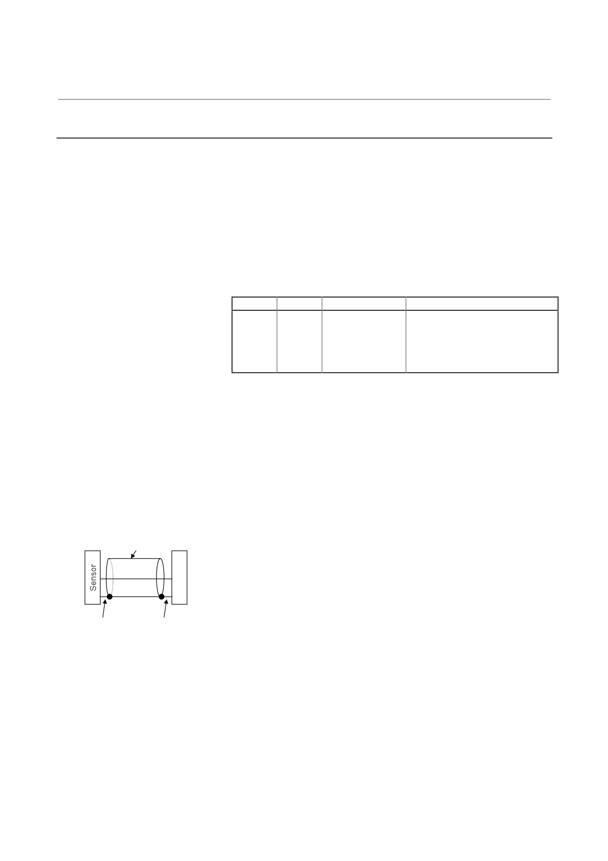
After emergency stop signal input, the motor is accelerated without
being decelerated. This alarm is issued also when the motor is not
deactivated
(the motor is not decelerated completely) when the
acceleration/deceleration time (initial parameter setting: 10 seconds)
has elapsed after emergency stop signal input.
Troubleshooting when this alarm is issued
(a) The parameter setting of the speed detector is incorrect.
Referring to Chapter 1 in "FANUC AC SPINDLE MOTOR
α series Parameter Manual (B-65160E)," set a correct time.
(b) The parameter setting of an acceleration/deceleration time is
not proper.
Check the parameter-set value and actual acceleration/
deceleration time, then set an actual acceleration/
deceleration time plus some margin.
FS0
FS15i
FS16i/16, PM-D/F
Description
6582
3082
4082
Acceleration/deceleration time
setting
- 161 -
3. TROUBLESHOOTING
AND ACTION
TROUBLESHOOTING
B-65165E/02
3.4.2
Alarm Code 39
The position where the one-rotation signal for Cs contour control is
generated is incorrect. This alarm is not issued when the parameter
indicated below is not set.
<1> When SPM TYPE2 is used, phase A/B/Z on the high-resolution
(1000 to 3000 λ) side of the high-resolution magnetic pulse coder
on the spindle side has a problem.
<2> When SPM TYPE4 is used, the spindle sensor connected to JY5 is
faulty.
Troubleshoot as in the case of alarm code 41.
FS0
FS15i
FS16i/16, PM-D/F
Description
6516#5
3016#5
4016#5
Whether the function for detecting
the one-rotation signal of the
detector for Cs contour control is
provided
1: The function is provided.
Troubleshooting when this alarm is issued (at the time of reference
position return on the Cs axis)
(a)
The setting of a parameter is incorrect.
Referring to Chapter 2 in "FANUC AC SPINDLE MOTOR
α series Parameter Manual
(B-65160E)," check the
parameter for sensor setting.
(b)
The sensor is not adjusted correctly.
Adjust the sensor according to Subsection 4.3.4 of Part I of
this manual. If the signal is not observed, replace the sensor.
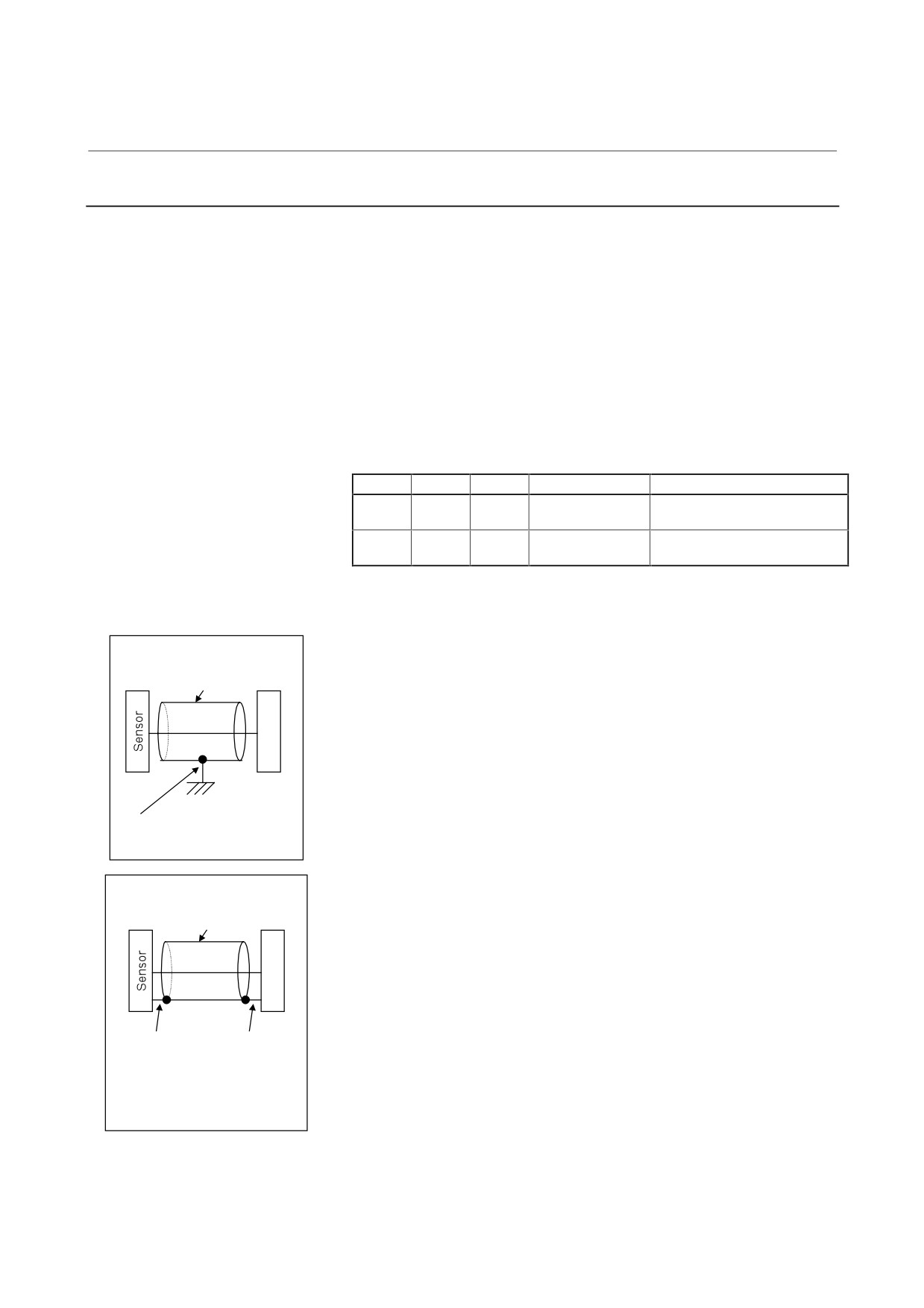
(c)
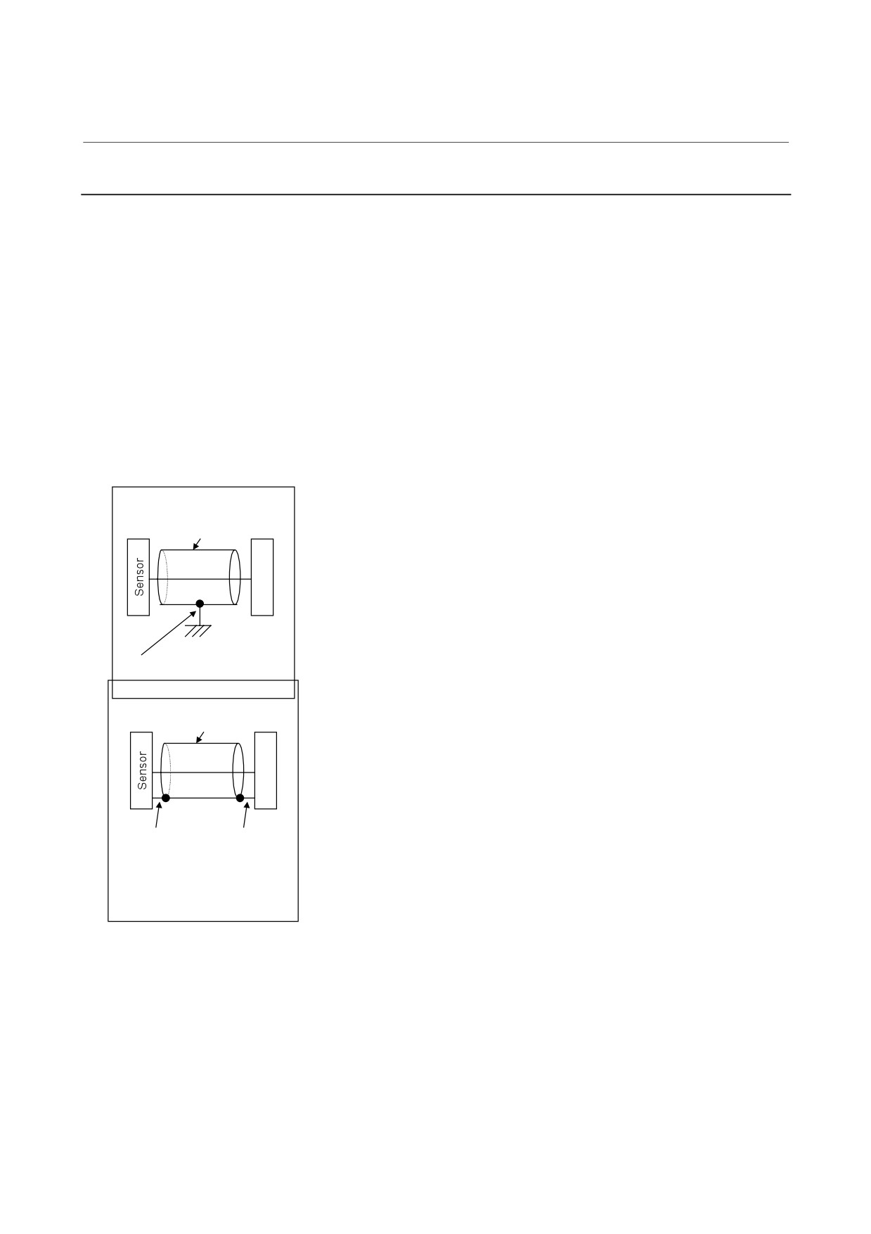
The shielding of the cable between the preamplifier and
SPM is faulty.
Shielded cable
Referring to Chapter 9, "Connection," in "FANUC SERVO
AMPLIFIER α series Descriptions (B-65162E)," check the
S
shielding of the cable.
P
M
(d)
The signal cable is bundled with the servo motor power line.
If the cable between the preamplifier and SPM is bundled
with the servo motor power line, separate them from each
The cable is
The cable is
other.
connected to the
connected to
pin specified in the
pin 10 on the
(e)
Improve the cable routing between the motor and
specifications on
SPM side.
preamplifier.
the sensor side.
If the cables
(including those within a terminal box)
extending from the motor to the preamplifier are close to the
power line, separate the cables from the power line.
(f)
The SPM is faulty.
Replace the SPM or SPM control printed circuit board.
- 162 -
3. TROUBLESHOOTING
B-65165E/02
TROUBLESHOOTING
AND ACTION
3.4.2.1
Alarm code 40
The one-rotation signal for Cs contour control is not generated.
<1> When SPM TYPE2 is used, phase A/B/Z on the high-resolution
(1000 to 3000 λ) side of the high-resolution magnetic pulse coder
on the spindle side has a problem.
<2> When SPM TYPE4 is used, the spindle sensor connected to JY5 is
faulty.
Troubleshoot as in the case of alarm code 42.
Troubleshooting when this alarm is issued (at the time of reference
position return on the Cs axis)
(a) The setting of a parameter is incorrect.
Referring to Chapter 2 in "FANUC AC SPINDLE MOTOR
α series Parameter Manual
(B-65160E)," check the
parameter for sensor setting.
(b) The sensor is not adjusted correctly.
Adjust the sensor according to Subsection 4.3.4 of Part I of
this manual. If the signal is not observed, replace the sensor.
(c) The cable is disconnected.
Check the check pin PSD on the check board. If the signal is
not observed per sensor rotation, replace the cable.
(d) The SPM is faulty.
Replace the SPM or SPM control printed circuit board.
- 163 -
3. TROUBLESHOOTING
AND ACTION
TROUBLESHOOTING
B-65165E/02
3.4.2.2 Alarm code 41
<1> The position where the one-rotation signal of the α position coder
is generated is incorrect.
<2> The position where the one-rotation signal of the MZ sensor or BZ
sensor is generated is incorrect.
<3> The position where the one-rotation signal of α position coder S is
generated is incorrect.
(1) If orientation based on the external one-rotation method is used
(a) The settings of parameters are incorrect.
Check that the gear ratio data matches the specification of
the machine.
FS0
FS15
FS15i
FS16i/16, PM-D/F
Description
6935
3315
3171
4171
Number of teeth on the spindle
6937
3317
3173
4173
side
6936
3316
3172
4172
Number of teeth on the position
6938
3318
3174
4174
detector side
(b) Slippage between the spindle and motor
Check that there is no slippage between the spindle and
motor. Orientation based on the external one-rotation
α position coder
method is not applicable to V-belt connection.
Shielded cable
(2)
Troubleshooting in other cases
S
(a) The setting of a parameter is incorrect.
P
Referring to "FANUC AC SPINDLE MOTOR α series
M
Parameter Manual (B-65160E)," check the parameter for
sensor setting.
(b) A sensor (MZ sensor or BZ sensor) is not adjusted correctly.
Connected to the
frame
Adjust the sensor according to Subsection 4.3.4 of Part I of
ground via a cable clamp.
this manual. If the signal is not observed, replace the sensor.
(c) The α position coder is faulty.
MZ or BZ sensor
Check the check pin PSD on the spindle check board. If the
Shielded cable
signal is not generated per rotation, replace the position
coder.
S
(d) The shielding of the cable between the sensor and SPM is
P
faulty.
M
Referring to Chapter 9, "Connection," in "FANUC SERVO
AMPLIFIER α series Descriptions (B-65162E)," check the
The cable is
The cable
is
shielding of the cable.
connected to the
connected to
(e) The signal cable is bundled with the servo motor power line.
pin specified in
pin 10 on the
the specifications
SPM side.
If the cable between the sensor and SPM is bundled with the
on the sensor
servo motor power line, separate them from each other.
side.
(f) The SPM is faulty.
Replace the SPM or SPM control printed circuit board.
- 164 -

3. TROUBLESHOOTING
B-65165E/02
TROUBLESHOOTING
AND ACTION
3.4.2.3 Alarm code 42
<1> The one-rotation signal of the α position coder is not generated.
<2> The one-rotation signal of the MZ sensor or BZ sensor is not
generated.
<3> The one-rotation signal of α position coder S is not generated.
Troubleshooting when this alarm is issued
(a) The setting of a parameter is incorrect.
Referring to "FANUC AC SPINDLE MOTOR α series
Parameter Manual (B-65160E)," check the parameter for
sensor setting.
(b) The MZ sensor or BZ sensor is not adjusted correctly.
Adjust the sensor according to Subsection 4.3.4 of Part I of
this manual. If the sensor cannot be adjusted or the signal is
not observed, replace the connection cable and sensor.
(c) The α position coder is faulty.
Check the check pin PSD on the spindle check board. If the
signal is not generated per rotation, replace the connection
cable and position coder.
(d) The SPM is faulty.
Replace the SPM or SPM control printed circuit board.
3.4.2.4 Alarm code 43
The position coder signal of the spindle on the mater side used in the
differential speed mode is disconnected.
Troubleshoot as in the case of alarm code 27.
3.4.2.5 Alarm code 44
An error occurred in the A/D converter.
When this alarm is issued, replace the SPM or SPM control printed
circuit board.
3.4.2.6 Alarm code 46
The one-rotation signal of the position coder cannot be detected
normally during thread cutting.
Troubleshoot as in the case of alarm code 41.
- 165 -
3. TROUBLESHOOTING
AND ACTION
TROUBLESHOOTING
B-65165E/02
3.4.2.7 Alarm code 47
<1> The count value of α position coder signal pulses is abnormal.
<2> The pulse count value of the MZ sensor or BZ sensor is abnormal.
Phases A and B for the position coder have a feedback pulse count of
4096 p/rev per spindle rotation. The SPM checks the pulse counts of
phases A and B equivalent to the position coder each time a one-
rotation signal is generated. The alarm is issued when a pulse count
beyond the specified range is detected.
(1)
If this alarm is issued when the cable is moved (as in the case
where the spindle moves)
(a) The connector has a bad contact, or the cable is
disconnected.
α position coder
The conductor may be broken. Replace the cable. If coolant
Shielded cable
has penetrated into the connector, clean the connector.
S
(2)
Troubleshooting in other cases
P
(a) The setting of a parameter is incorrect.
M
Referring to "FANUC AC SPINDLE MOTOR α series
Parameter Manual (B-65160E)," check the parameter for
sensor setting.
Connected to the frame
(b) A sensor (MZ sensor or BZ sensor) is not adjusted correctly.
ground via a cable clamp.
Adjust the sensor according to Subsection 4.3.4 of Part I of
MZ or BZ sensor
this manual.
Shielded cable
(c) The shielding of the cable between the sensor and SPM is
faulty.
S
Referring to Chapter 9, "Connection," in "FANUC SERVO
P
M
AMPLIFIER α series Descriptions (B-65162E)," check the
shielding of the cable.
(d) The signal cable is bundled with the servo motor power line.
The cable is
The cable is
If the cable between the sensor and SPM is bundled with the
connected to the
connected to
pin specified in
pin 10 on the
servo motor power line, separate them from each other.
the specifications
SPM side.
(e) The SPM is faulty.
on the sensor
side.
Replace the SPM or SPM control printed circuit board.
- 166 -
3. TROUBLESHOOTING
B-65165E/02
TROUBLESHOOTING
AND ACTION
3.4.2.8 Alarm code 49
In the differential speed mode, the spindle speed on the master side
(remote) converted to a motor speed on the slave side (local) exceeded
the maximum allowable speed of the motor.
Troubleshooting when this alarm is issued
A differential speed is calculated by multiplying the speed on the
target speed by a gear ratio.
Ensure that the maximum allowable speed of the motor is not
exceeded.
3.4.2.9 Alarm code 50
A value obtained by internal calculation in spindle synchronization
exceeded the allowable range.
Troubleshooting when this alarm is issued
(a) The setting of parameters for gear ratio setting is incorrect.
Check if an excessively large gear ratio is set.
(b) Position gain setting limit
If correct gear ratio data is set, increase the position gain
value in spindle synchronization.
FS0
FS15i
FS16i/16, PM-D/F
Description
6556
3056
4056
Gear ratio between the spindle and
to
to
to
motor
6559
3059
4059
6565
3065
4065
Position gain in the servo
to
to
to
mode/spindle synchronization
6568
3068
4068
3.4.2.10 Alarm code 51
The PSM detected that the DC link voltage was excessively low.
(1) If the PSM indicates alarm code 4
Troubleshoot according to the description of alarm code
4
provided in Section 3.1 of Part II.
(2) If the PSM indicates no alarm
(a) A cable is faulty.
The connection cable between the PSM (JX1B) and SPM
(JX1A) is faulty. Replace the cable.
(b) The SPM is faulty.
Replace the SPM or SPM control printed circuit board.
- 167 -
3. TROUBLESHOOTING
AND ACTION
TROUBLESHOOTING
B-65165E/02
3.4.2.11 Alarm codes 52 and 53
The synchronization signal (ITP) in communication data transferred to
and from the CNC stopped.
Troubleshooting when this alarm is issued
(a) The SPM is faulty.
Replace the SPM or SPM control printed circuit board.
(b) The CNC is faulty.
Replace the board or module related to the serial spindle.
3.4.2.12 Alarm code 54
A large current flowing in the motor for a long time was detected.
Troubleshoot as in the case of alarm code 29.
3.4.2.13 Alarm code 55
In spindle switching control or output switching control, a mismatch
between the switching request signal (SPSL or RSL) and the power line
state check signal (MCFN, MFNHG, RCH, or RCHHG) continues
during motor activation.
Troubleshooting when this alarm is issued
(a) The magnetic contactor
(switch unit) for power line
switching is faulty.
If the contact is inoperative, check the power supply of the
magnetic contactor. If the magnetic contactor is still
inoperative, replace the magnetic contactor.
(b) The I/O unit or wiring for checking the contact of the
magnetic contactor is faulty.
If a defect is found in the I/O unit or wiring, replace the I/O
unit or wiring.
(c) The sequence (ladder) is incorrect.
Modify the sequence so that switching is not performed
during activation. For details of the signals, refer to Chapter
10, "Interface Signals," in "FANUC SERVO AMPLIFIER α
series Descriptions (B-65162E)."
- 168 -
3. TROUBLESHOOTING
B-65165E/02
TROUBLESHOOTING
AND ACTION
3.4.2.14 Alarm code 56
The cooling fan of the control circuit stopped.
When this alarm is issued, replace the SPM or the internal cooling
fan of the SPM. When replacing the internal cooling fan, see
Chapter 4.
3.4.2.15 Alarm code 57
The temperature of the regenerative resistance of the PSM (resistance
regenerative type) is excessively high. The PSM is faulty.
(1) If the PSM indicates alarm code 8 or above
Troubleshoot according to the description of alarm code 8 (or the
pertinent code) provided in Section 3.1 of Part II.
(2) If the PSM indicates no alarm
(a) A cable is faulty.
The connection cable between the PSM (JX1B) and SPM
(JX1A) is faulty. Replace the cable.
(b) The SPM is faulty.
Replace the SPM or SPM control printed circuit board.
3.4.2.16 Alarm code 58
The temperature of the main circuit-cooling fan of the PSM is
abnormally high.
(1) If the PSM indicates alarm code 3
Troubleshoot according to the description of alarm code
3
provided in Section 3.1 of Part II.
(2) If the PSM indicates no alarm
(a) A cable is faulty.
The connection cable between the PSM (JX1B) and SPM
(JX1A) is faulty. Replace the cable.
(b) The SPM is faulty.
Replace the SPM or SPM control printed circuit board.
- 169 -
3. TROUBLESHOOTING
AND ACTION
TROUBLESHOOTING
B-65165E/02
3.4.2.17 Alarm code 59
The internal cooling fan of the PSM stopped.
(1) If the PSM indicates alarm code 2
Troubleshoot according to the description of alarm code
2
provided in Section 3.1 of Part II.
(2) If the PSM indicates no alarm
(a) A cable is faulty.
The connection cable between the PSM (JX1B) and SPM
(JX1A) is faulty. Replace the cable.
(b) The SPM is faulty.
Replace the SPM or SPM control printed circuit board.
- 170 -
3. TROUBLESHOOTING
B-65165E/02
TROUBLESHOOTING
AND ACTION
3.4.3
αC Series Spindle Amplifier Module
For the αC series, only those alarm codes that have the same number as
for the α series and require troubleshooting different from the α series
are described.
For an alarm code not covered by this subsection, see the description of
the alarm code for the α series spindle amplifier module.
3.4.3.1
Alarm code 12
An excessively high motor current was detected.
An excessively high current flowed into the DC link of the main circuit.
For SPMC-2.2 to SPMC-11
The power module (IPM) of the main circuit detected an excessive load,
excessively high current, or decrease in control supply voltage.
(1)
If an SPMC from SPMC-2.2 to SPMC-11 indicates this alarm
Check alarm code 09 as well.
(2)
If this alarm is issued immediately after a spindle move command
is specified
(a) The motor power line is faulty.
Check for a short circuit between motor power lines and
short-circuit to ground, and replace the power line as
required.
(b) The motor winding has an insulation failure.
If the motor is short-circuited to ground, replace the motor.
(c) The parameters specific to the motor are not set correctly.
Refer to "FANUC AC SPINDLE MOTOR α series
Parameter Manual (B-65160E)."
(d) The SPMC is faulty.
A power element (IGBT, IPM) may be destroyed. Replace
the SPMC.
(3)
If this alarm is issued during spindle rotation
(a) Belt slippage
The belt between the spindle and motor may be slipping.
Clean the pulley and run the belt again.
(b) The parameters specific to the motor are not set correctly.
Referring to "FANUC AC SPINDLE MOTOR α series
Parameter Manual
(B-65160E)," check the parameters
specific to the motor.
- 171 -
3. TROUBLESHOOTING
AND ACTION
TROUBLESHOOTING
B-65165E/02
(c) A power element is destroyed.
A power element (IGBT, IPM) may be destroyed. Replace
the SPM.
If the amplifier setting condition is not satisfied, or cooling is
insufficient because the heat sink is dirty, the power
elements may be destroyed.
When the heat sink on the back of the amplifier is too dirty,
clean the heat sink, for example, by blowing air. Consider
the use of a structure that prevents the heat sink from being
directly exposed to coolant.
For the setting condition, refer to "FANUC SERVO
AMPLIFIER α series Descriptions (B-65162E)."
3.4.3.2
Alarm code 35
The motor speed calculated from the position coder much differs from
the motor speed estimated in the SPMC.
(1) If this alarm is issued when a rotation command is specified
(a) The setting of parameters for position coder setting is
incorrect.
Set the bits related to the rotation directions of the position
coder and spindle and the rotation directions of the spindle
and motor. For details, refer to "FANUC AC SPINDLE
MOTOR α series Parameter Manual (B-65160E)."
(b) The setting of parameters for gear ratio setting is incorrect.
Check if incorrect gear ratio data is set. The gear ratio data is
used for conversion from the position coder to a motor speed.
So, be sure to set correct values.
FS0
FS15i
FS16i/16, PM-D/F
Description
6556
3056
4056
Gear ratio between the spindle and
to
to
to
motor
6559
3059
4059
(c) Slippage between the spindle and motor
Make an adjustment to prevent the belt from slipping.
(2) If this alarm is issued during cutting
The motor speed is decreased because of an overload. Review the
cutting condition.
- 172 -

3. TROUBLESHOOTING
B-65165E/02
TROUBLESHOOTING
AND ACTION
3.5
POWER-FAILURE BACKUP MODULE
When an alarm is issued, the one-digit 7-segment LED indicates an
alarm code.
Indicates an alarm code (01 or above).
3.5.1
Alarm Code 1
(1) Meaning
Sub-module C cannot be charged.
(2) Cause and troubleshooting
(a) Sub-module C connection error
→ Check the connection.
(b) Charging circuit failure
→ Replace the power-failure backup module.
3.5.2
Alarm Code 2
(1) Meaning
After sub-module C was charged, the voltage decreased for a
cause.
(2) Cause and troubleshooting
(a) Charging circuit failure
→ Replace the power-failure backup module.
3.5.3
Alarm Code 3
(1) Meaning
An abnormal current flowed in sub-module R.
(2) Cause and troubleshooting
(a) Excessive regenerated power
→ If the sum of maximum servo motor outputs exceeds 20
kW, use two sub-module R units.
(b) Regenerative circuit failure
→ Replace the power-failure backup module.
- 173 -
3. TROUBLESHOOTING
AND ACTION
TROUBLESHOOTING
B-65165E/02
3.5.4
Alarm Code 4
(1) Meaning
The regenerative resistance in sub-module R is overheated.
(2) Cause and troubleshooting
(a) Sub-module R is placed in conductive state at all times
because of a regenerative circuit failure.
→ Replace the power-failure backup module.
3.5.5
Alarm Code 5
(1) Meaning
The supply voltage for driving the thyristor decreased.
(2) Cause and troubleshooting
(a) The power supply circuit for driving the thyristor is
abnormal.
→ Replace the power-failure backup module.
- 174 -
4. HOW TO REPLACE THE FUSES
B-65165E/02
TROUBLESHOOTING
AND PRINTED CIRCUIT BOARDS
4
HOW TO REPLACE THE FUSES AND
PRINTED CIRCUIT BOARDS
WARNING
Before replacing fuses or printed-circuit boards,
make sure that the recharge-under-way LED (red) is
off.
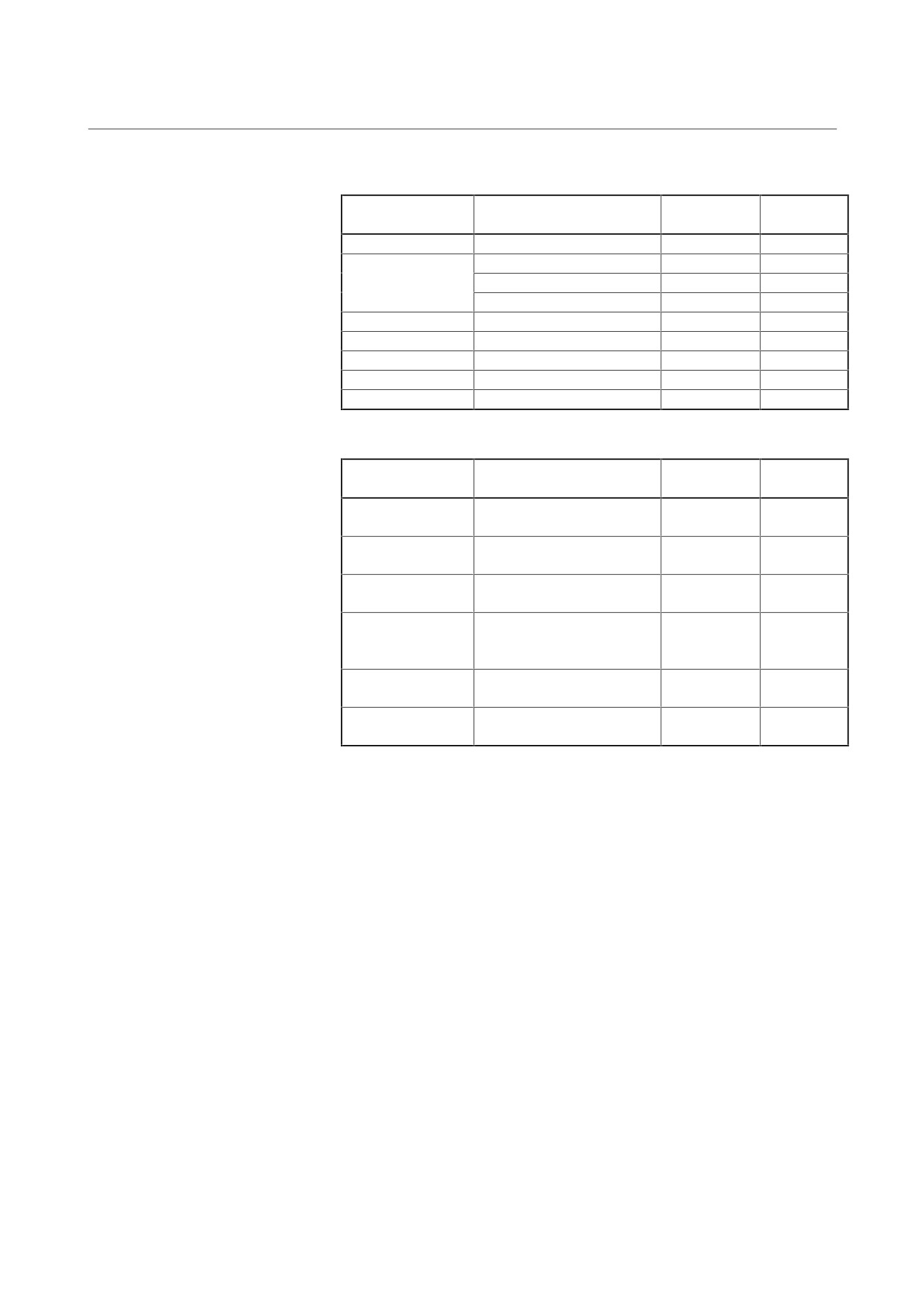
Before replacing fuses or printed circuit boards, see the table given
below to find which section or subsection in this manual provides
information about the related replacement procedure.
- 175 -
4. HOW TO REPLACE THE FUSES
AND PRINTED CIRCUIT BOARDS
TROUBLESHOOTING
B-65165E/02
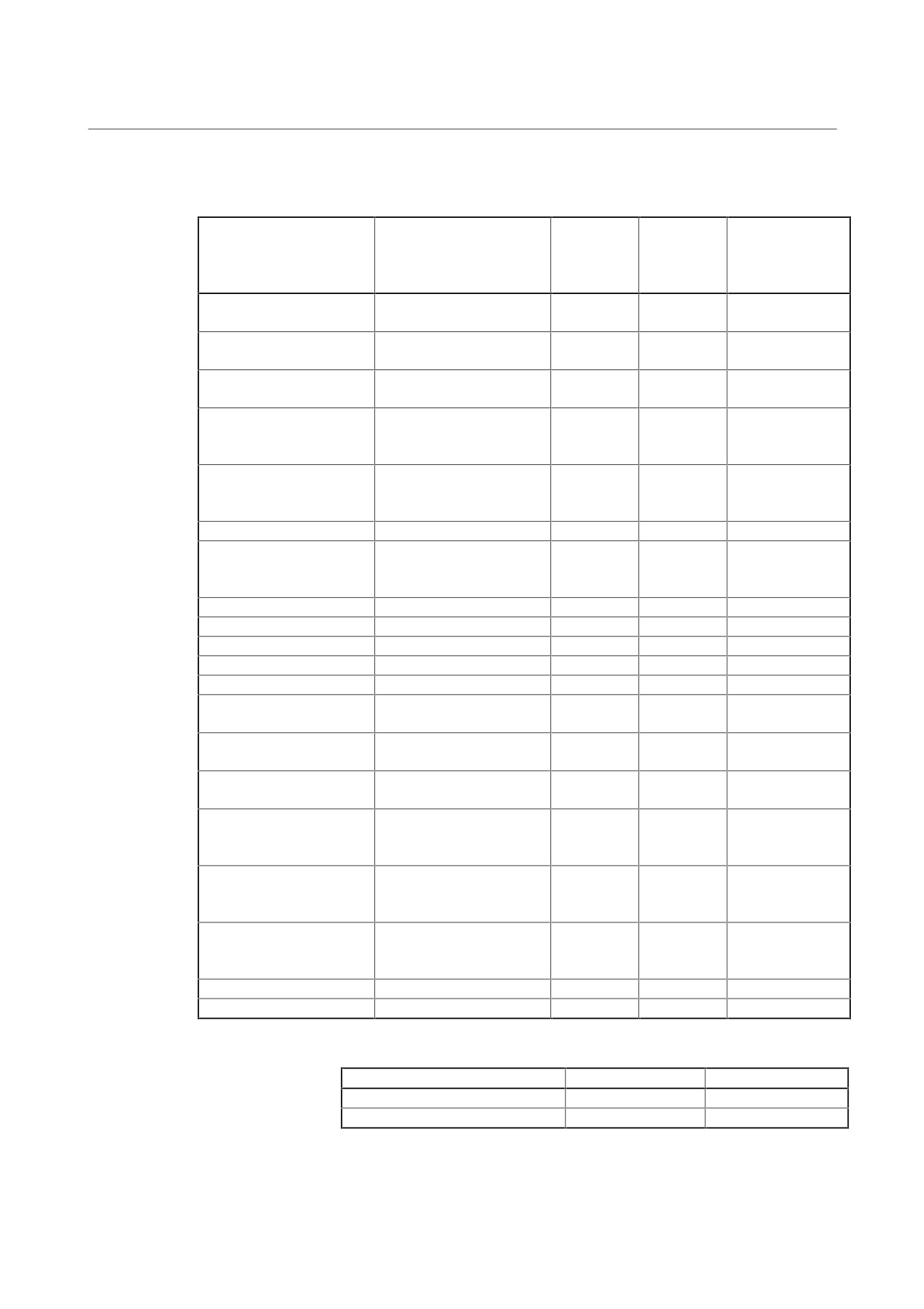
(1) Power supply module
Case
Fuse
Model
Drawing No.
disassembly
replacement
PSM-5.5 to 11
A06B-6077-H106 to 111
4.1.1
4.2.1(1)
PSM-15 to 37
A06B-6087-H115 to 137
4.1.2
4.2.1(1), (3)
A06B-6077-H115 to 130
4.1.2
4.2.1(2), (3)
A06B-6071-H115 to 130
4.1.3
4.2.1(2), (3)
PSM-45, 55
A06B-6087-H145 to 155
4.1.4
4.2.1(1)
PSM-15HV to 45HV
A06B-6091-H115 to 145
4.1.2
4.2.1(1), (3)
PSM-75HV
A06B-6087-H175
4.1.4
4.2.1(1)
PSMR-3, 5.5
A06B-6081-H103, H106
4.1.1
4.2.1(4), (5)
PSMV-11HV
A06B-6098-H111
4.1.2
4.2.1(1), (6)
(2) Servo amplifier module
Case
Fuse
Model
Drawing No.
disassembly
replacement
SVM1-12 to 130
A06B-6079-H101 to H106
4.1.1
4.2.2(1)
A06B-6096-H101 to H106
SVM1-240, 360
A06B-6079-H107, H108
4.1.2
4.2.2(1),
A06B-6096-H107, H108
4.2.3(2)
SVM2-12/12 to
A06B-6079-H201 to H209
4.1.1
4.2.2(1)
80/80
A06B-6096-H201 to H209
SVM3-12/12/12 to
A06B-6079-H301 to H307
4.1.1
4.2.2(1)
SVM3-20/20/40
A06B-6080-H301 to H307
A06B-6096-H301 to H307
SVM1-20HV to
A06B-6085-H102 to H104
4.1.1
4.2.2(1)
60HV
A06B-6097-H102 to H104
SVM2-20/20HV to
A06B-6085-H201 to H206
4.1.1
4.2.2(1)
SVM2-60/60HV
A06B-6097-H201 to H206
- 176 -
4. HOW TO REPLACE THE FUSES
B-65165E/02
TROUBLESHOOTING
AND PRINTED CIRCUIT BOARDS
(3) Spindle amplifier module
(In drawing numbers,
# and the
subsequent part is omitted.)
Replacement of
Case
Fuse
the program ROM
Model
Drawing No.
disassembly
replacement
and the spindle
sensor module
SPM-2.2 to 11 TYPE1
A06B-6102-H202 to H211
4.1.1
4.2.3(1)
4.3.1(1)
TYPE4
A06B-6102-H102 to H111
SPM-15 to 30 TYPE1
A06B-6102-H215 to H230
4.1.2
4.2.3(1), (2)
4.3.1(1)
TYPE4
A06B-6102-H115 to H130
SPM-45 to 55 TYPE1
A06B-6102-H245, H255
4.1.4
4.2.3(1)
4.3.1(1)
TYPE4
A06B-6102-H145, H155
SPM-2.2 to 11 TYPE1
A06B-6078-H102 to H211
4.1.1
4.3.1(2)
TYPE2
A06B-6078-H302 to H311
TYPE4
SPM-15 to 30 TYPE1
A06B-6088-H115 to H230
4.1.2
4.2.3(2)
4.3.1(2)
TYPE2
A06B-6088-H315 to H330
TYPE4
SPM-11 to 30 TYPE3
A06B-6088-H411 to H430
4.1.3
4.2.3(2)
4.3.1(3)
SPM-45 to 55 TYPE1
A06B-6088-H245, H255
4.1.4
4.2.3(2)
4.3.1(2)
TYPE2
A06B-6088-H345, H355
TYPE4
A06B-6088-H145, H155
SPM-45 TYPE3
A06B-6088-H445
4.1.5
4.3.1(3)
Old SPM15 to 30
A06B-6078-H215 to H330
4.1.3
4.2.3(2), (3)
4.3.1(6), (7)
Old SPM11
A06B-6078-H411
4.1.3
4.2.3(2), (3)
4.3.1(7)
SPMC2.2 to 11
A06B-6082-H202 to H211
4.1.1
4.3.1(4)
SPMC15 to 26
A06B-6082-H215 to H226
4.1.2
4.2.3(2)
4.3.1(5)
SPM11HV TYPE1
A06B-6104-H211
4.1.1
4.2.3(1)
4.3.1(1)
TYPE4
A06B-6104-H111
SPM15HV to 45HV TYPE1
A06B-6104-H215 to H245
4.1.2
4.2.3(1), (2)
4.3.1(1)
TYPE4
A06B-6104-H115 to H145
SPM75HV TYPE1
A06B-6104-H275
4.1.4
4.2.3(1)
4.3.1(1)
TYPE4
A06B-6104-H175
SPM11HV TYPE1
A06B-6092-H211
4.1.1
4.3.1(2)
TYPE2
A06B-6092-H311
TYPE4
A06B-6092-H111
SPM15HV to 45HV TYPE1
A06B-6092-H215 to H245
4.1.2
4.2.3(2)
4.3.1(2)
TYPE2
A06B-6092-H315 to H345
TYPE4
A06B-6092-H115 to H145
SPM75HV TYPE1
A06B-6092-H275
4.1.4
4.3.1(2)
TYPE2
A06B-6092-H375
TYPE4
A06B-6092-H175
SPM15HV to 45HV TYPE3
A06B-6092-H415 to H445
4.1.4
4.2.3(2)
4.3.1(3)
SPM75HV TYPE3
A06B-6092-H475
4.1.5
4.3.1(3)
(4) Power-failure backup module
Drawing No.
Case disassembly
Fuse replacement
A06B-6077-H001
4.1.1
4.2.4(1)
A06B-6077-H002
4.1.1
4.2.4(1)
- 177 -
4. HOW TO REPLACE THE FUSES
AND PRINTED CIRCUIT BOARDS
TROUBLESHOOTING
B-65165E/02
4.1
CASE DISASSEMBLY
4.1.1
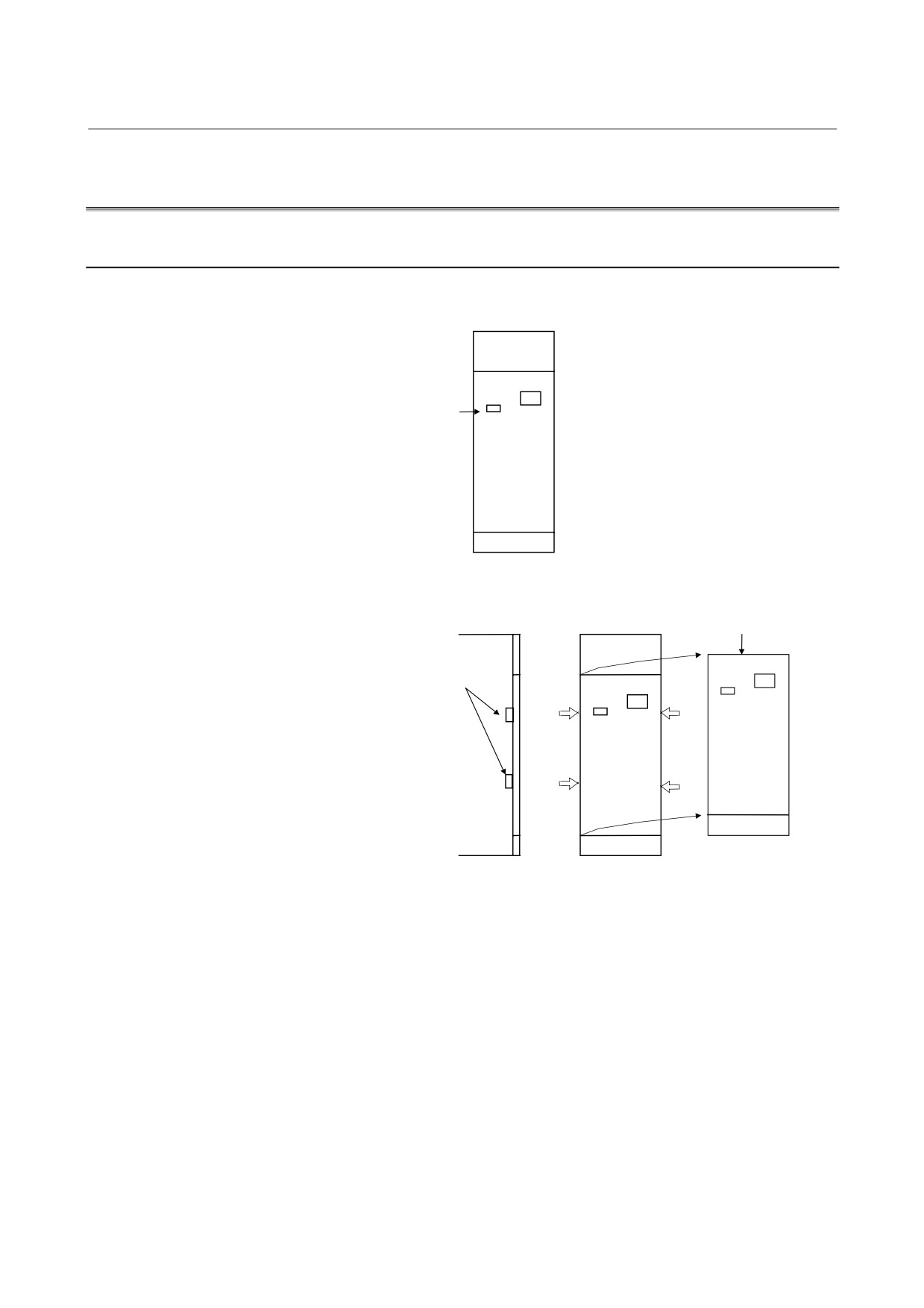
60/90 mm Width Modules
Make sure that the recharge-under-way LED (red) is off.
Recharge-under-way
LED
Remove the face plate.
Face plate
Remove the face plate
by inserting the tip of a
flat-blade screwdriver
at the hooks (four) on
the face plate.
Remove the cases.
- 178 -
4. HOW TO REPLACE THE FUSES
B-65165E/02
TROUBLESHOOTING
AND PRINTED CIRCUIT BOARDS
Case 2
Case 1
(cover)
(chassis)
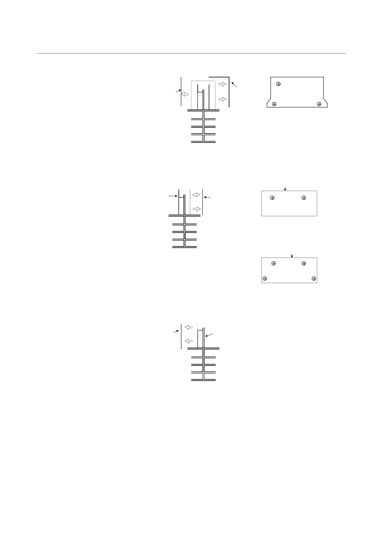
Remove the screws fastening the case
and the screws (5 × M4) holding down
the terminal board.
Remove the printed-circuit board.
• Cases for the SVM
Control circuit board
Wiring board
Control circuit
printed-circuit
board
Remove the screws (2 × M3) fastening the
printed-circuit board.
• Cases for the PSM and SPM
Control circuit board
Remove the screws (4 × M3) fastening the
printed-circuit board.
Remove the IPM.
IPM
Wiring board
<1> Remove the screws (5 × M5) fastening the IPM.
Then remove the wiring board.
<2> Remove the IPM.
Note) There is a snubber capacitor between the IPM
and wiring board. When re-assembling, do not
forget to mount it.
- 179 -
4. HOW TO REPLACE THE FUSES
AND PRINTED CIRCUIT BOARDS
TROUBLESHOOTING
B-65165E/02
4.1.2
150 mm Width Module (without the Connector Module)
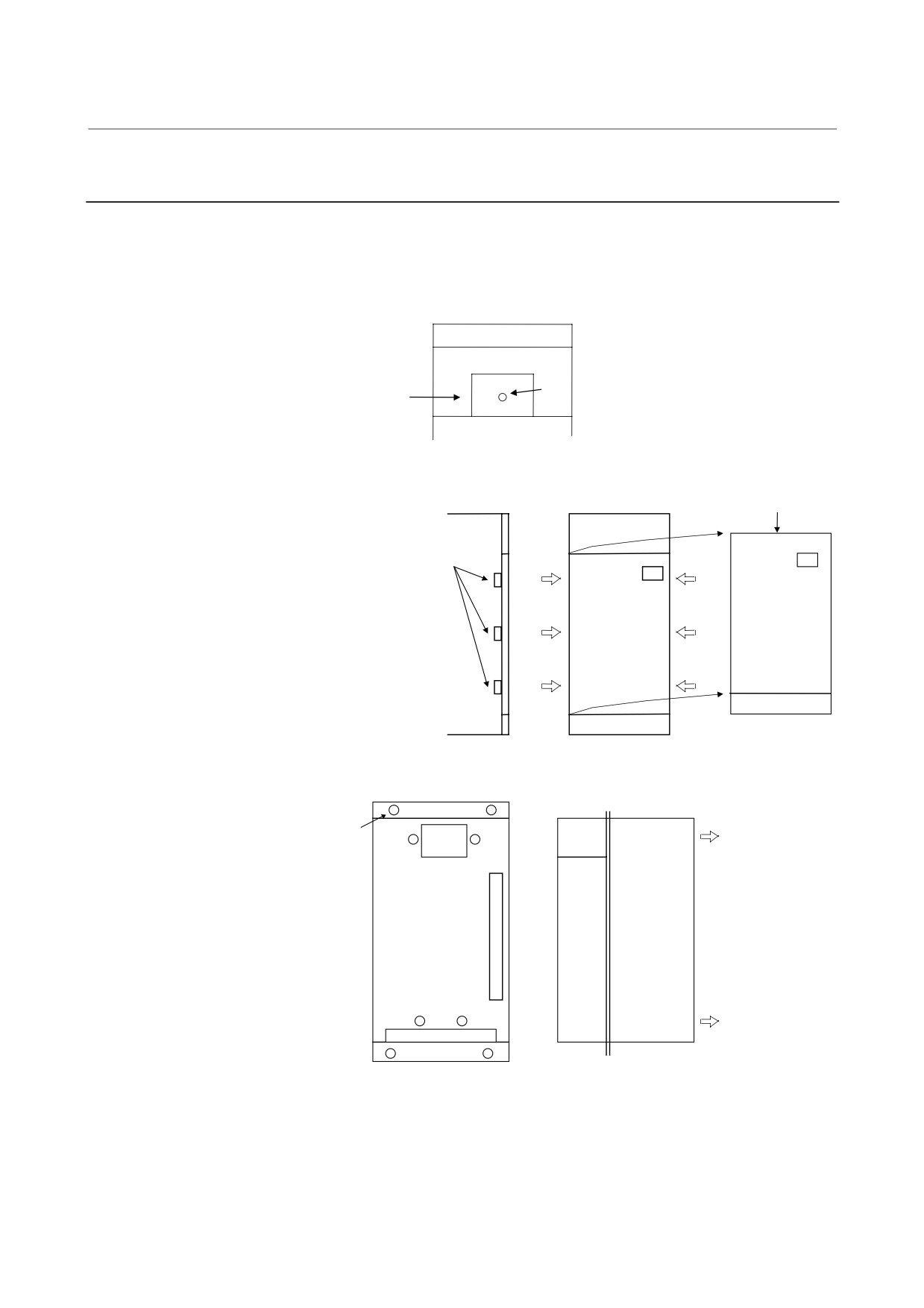
Make sure that the recharge-under-way LED (red) is off.
The recharge-under-way LED (red) is at the center of terminal board
TB1. Open the cover at the top of the module, and check the LED.
Recharge-under-way
Terminal
LED
board
Remove the face plate.
Face plate
Remove the face plate
by inserting the tip of a
flat-blade screwdriver
at the hooks
(six) on
the face plate.
Remove the case.
Screws (eight)
Fan
Remove the screws
(eight) fastening the
cases, and remove
Heat
Case
the case by pulling it
sink
off the flange
surface.
- 180 -
4. HOW TO REPLACE THE FUSES
B-65165E/02
TROUBLESHOOTING
AND PRINTED CIRCUIT BOARDS
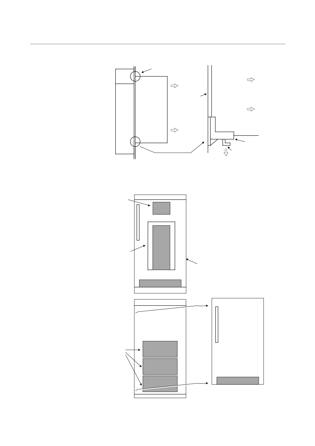
Remove the printed-circuit board.
PCB supports (two)
Fan
Wiring
Printed-circuit
board
board
Heat
sink
Printed-circuit
board
PCB support
Hook
While spreading the PCB support hooks, pull the printed-circuit
board off the flange surface to remove it.
Remove the IGBT.
TB1
<1> Remove terminal board TB1 (for SPM
only).
<2> Remove the electrolytic capacitor
board.
<3> Remove the wiring board.
<4> Remove the IGBT.
Capacitor board
Wiring
board
IGBT
- 181 -
4. HOW TO REPLACE THE FUSES
AND PRINTED CIRCUIT BOARDS
TROUBLESHOOTING
B-65165E/02
4.1.3
150 mm Width Module (with the Connector Module)
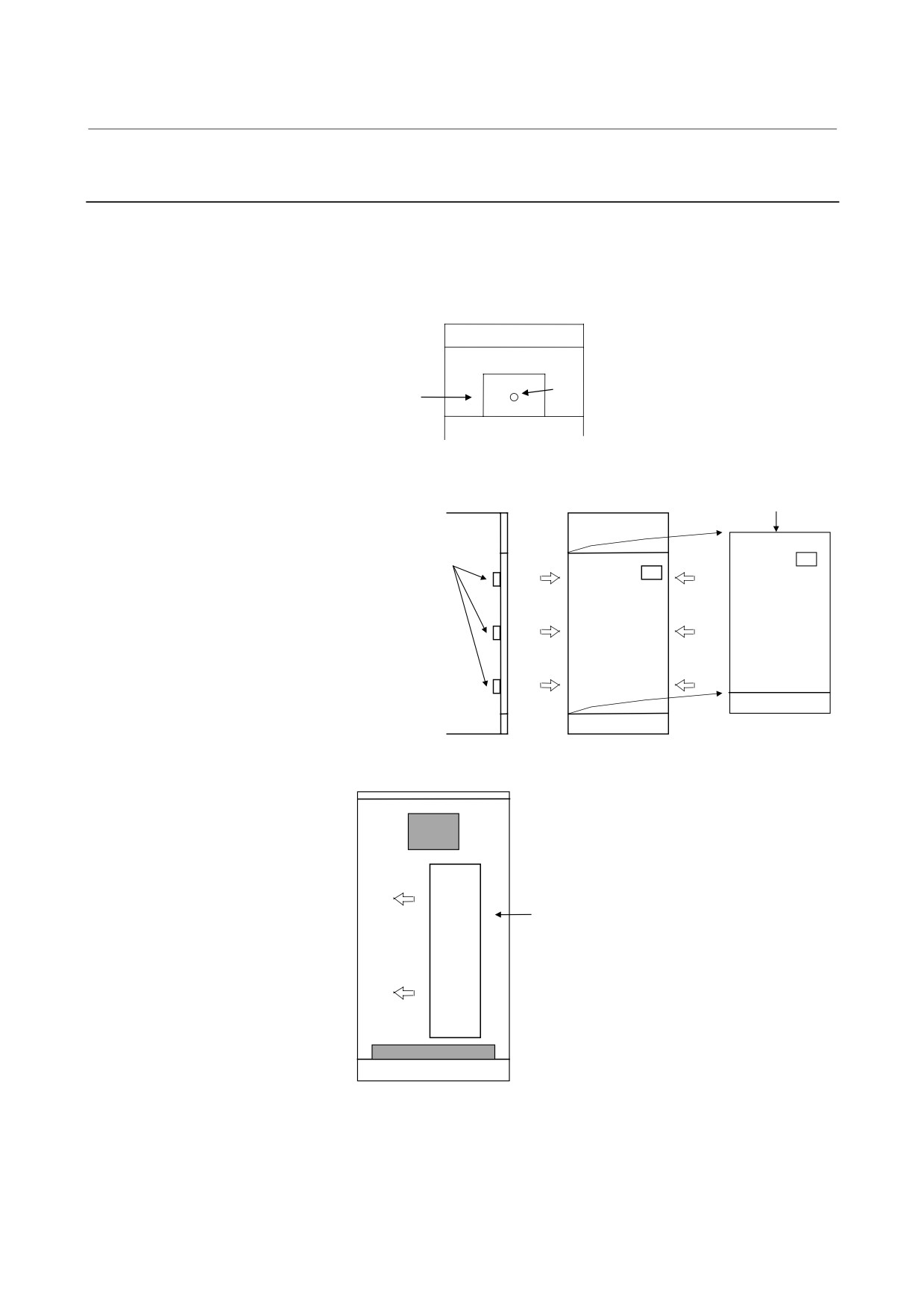
Make sure that the recharge-under-way LED (red) is off.
The recharge-under-way LED (red) is at the center of terminal board
TB1. Open the cover at the top of the module, and check the LED.
Recharge-under-way
Terminal
LED
board
Remove the face plate.
Face plate
Remove the face
plate by inserting
the tip of a flat-blade
screwdriver at the
hooks (six) on the
face plate.
Remove connector PCB.
Remove the self-tapping screws holding down
connector PCB, and shift it in the direction
indicated with an arrow (left) to remove the
printed-circuit board.
Connector PCB
- 182 -
4. HOW TO REPLACE THE FUSES
B-65165E/02
TROUBLESHOOTING
AND PRINTED CIRCUIT BOARDS
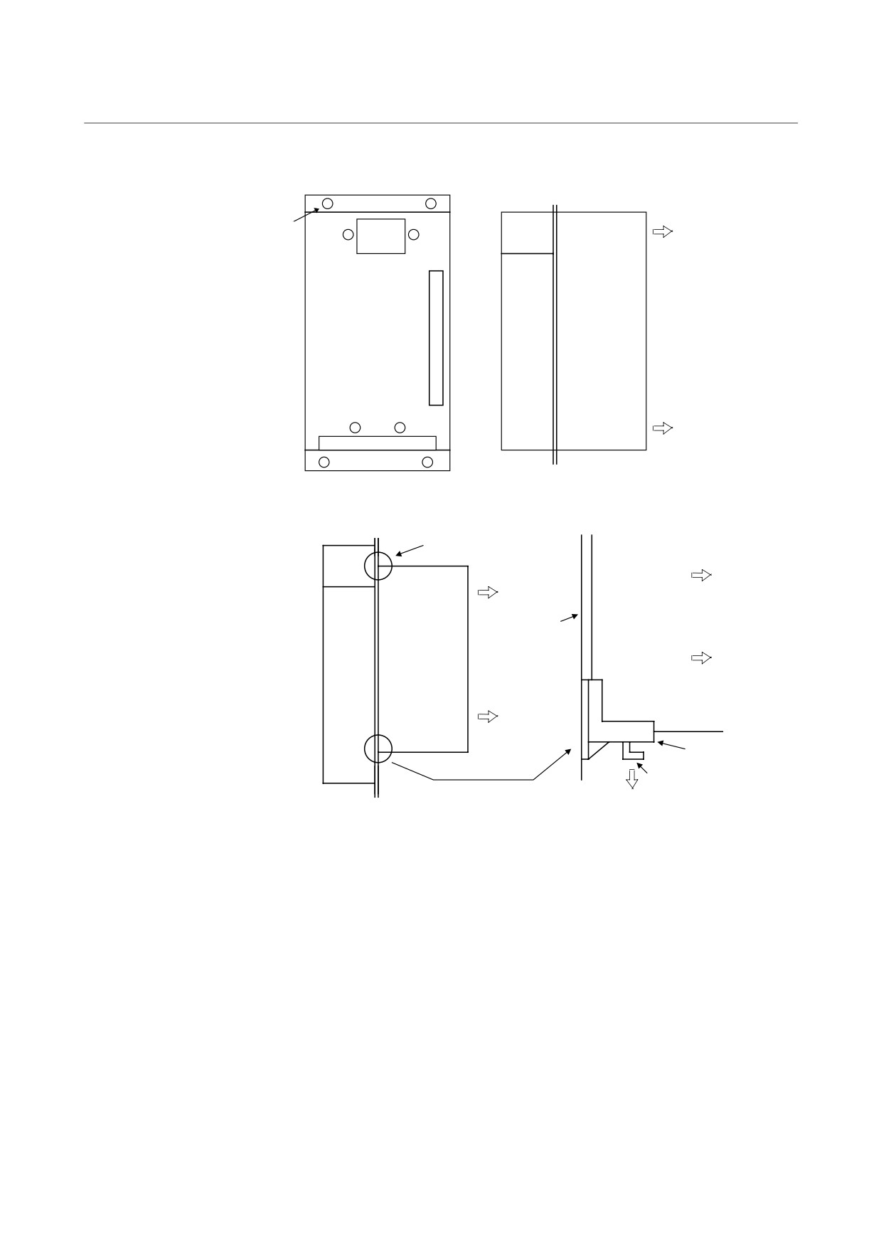
Remove the case.
Screws (eight)
Fan
Remove the screws
(eight) fastening the
cases, and remove
Heat
the case by pulling it
Case
off the flange
sink
surface.
Remove the printed-circuit board.
PCB supports (two)
Fan
Printed-circuit
board
Wiring
board
Heat
sink
Printed-circuit
board
PCB support
Hook
While spreading the PCB support hooks, pull the printed-circuit
board off the flange surface to remove it.
- 183 -
4. HOW TO REPLACE THE FUSES
AND PRINTED CIRCUIT BOARDS
TROUBLESHOOTING
B-65165E/02
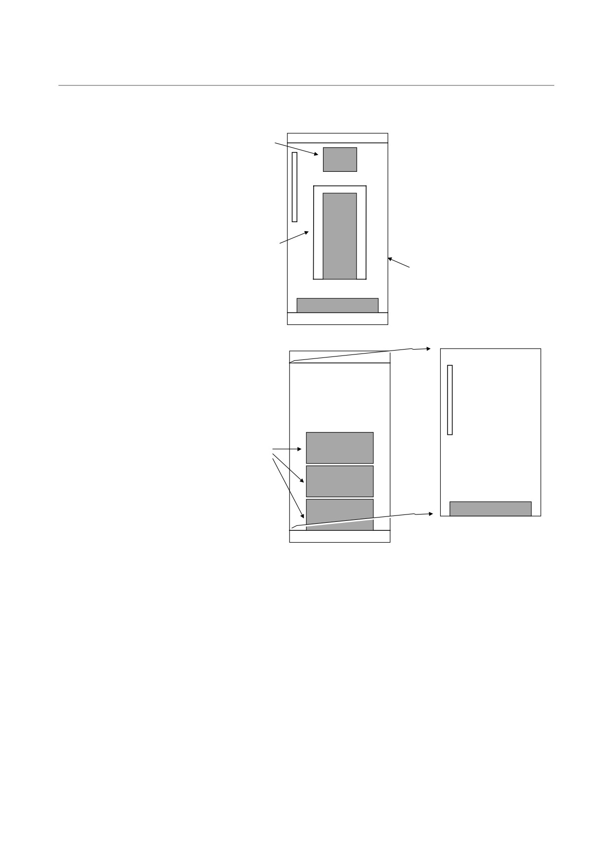
Remove the IGBT.
TB1
<1> Remove terminal board TB1
(for SPM only).
<2> Remove the electrolytic
capacitor board.
<3> Remove the wiring board.
<4> Remove the IGBT.
Capacitor board
Wiring
board
IGBT
Wiring
board
- 184 -
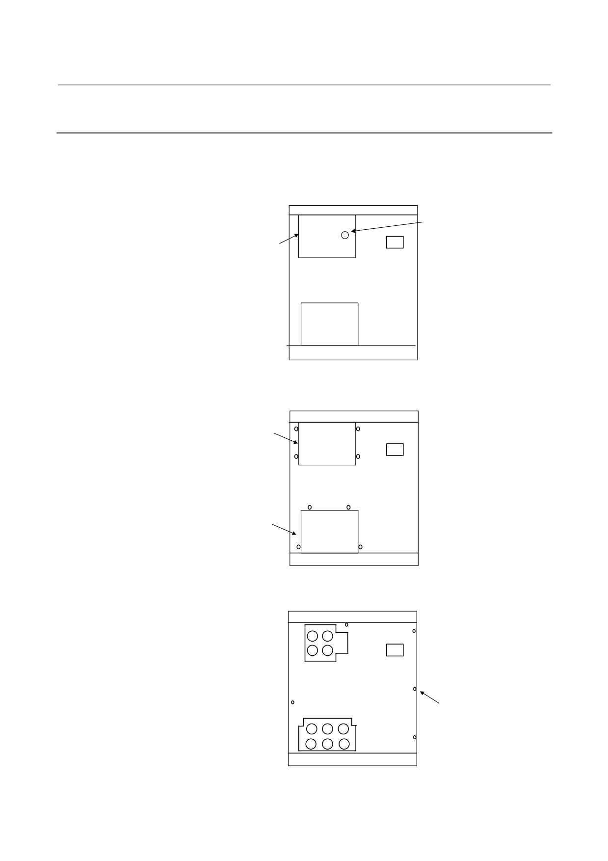
4. HOW TO REPLACE THE FUSES
B-65165E/02
TROUBLESHOOTING
AND PRINTED CIRCUIT BOARDS
4.1.4
300-mm Wide Module (without the Connector Module)
Make sure that the recharge-under-way LED (red) is off. View the
recharge-under-way LED (red) from the upper part of the DC link
cover.
LED
Cover
Remove the DC link cover and motor power line cover.
DC link
cover
Remove the self-tapping
screws (8 × M4) from
the DC link cover and
motor power line cover.
Motor power
line cover
Remove the face plate.
Remove the screws
(5 × M4) from the
face plate.
Screw (× 5)
- 185 -
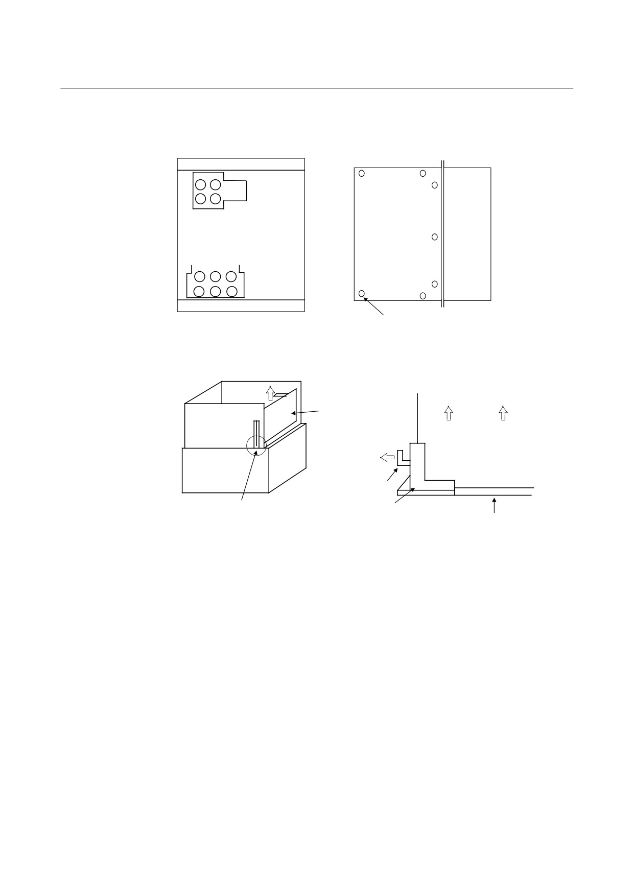
4. HOW TO REPLACE THE FUSES
AND PRINTED CIRCUIT BOARDS
TROUBLESHOOTING
B-65165E/02
Remove the right side plate.
Remove the
screws (7 × M4)
from the right side
Right side plate
plate.
Heat sink
Screw (7 × M4)
Remove the control printed circuit board.
Control printed circuit
board
Bottom plate
Control printed circuit
board
Heat sink
Hook
PCB support
PCB support
Wiring board
Insert the tip of a screwdriver into the opening on the bottom
plate, and while spreading the hook of the PCB support, pull
the printed circuit board off the flange surface toward you.
- 186 -
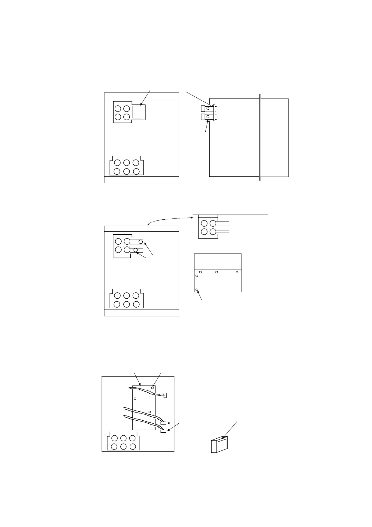
4. HOW TO REPLACE THE FUSES
B-65165E/02
TROUBLESHOOTING
AND PRINTED CIRCUIT BOARDS
Remove the LED board for the recharge indicator.
LED board for the recharge indicator
Remove the
screws (2 × M4)
from the LED
board, and remove
the board.
Heat sink
Screw (× 2)
Remove the top plate.
<1> Remove the screws (2 × M5)
from the DC link jumper.
<2> Remove the screws (5 × M4)
from the top plate.
<3> Remove the top plate. (The top
plate comes off together with
the terminal block TB1.)
Screw (2 × M5)
Heat sink
Top plate
Screw (5 × M4)
Remove the driver printed circuit board.
<1> From the two connectors,
detach the cables of the current
Driver printed circuit board
sensor.
Screw × 3
<2> Remove the screws (3 × M4)
from the driver printed circuit
board.
<3> Pull up the driver printed circuit
board to remove it.
Carefully insert the tip of a screwdriver
and pull out the cable. (Be careful not
to force the screwdriver into the
Connector × 2
connector; otherwise, the claw may
break.)
- 187 -