FANUC Alpha Series Motors and Modular Drives. Maintenance Manual (GFZ-65165E/02) - page 6
3. TROUBLESHOOTING
AND ACTION
TROUBLESHOOTING
B-65165E/02
3.2
SERVO AMPLIFIER MODULE
3.2.1
Abnormal Current Alarms (8, 9, A, b, C, d, and E in the LED
display)
(1) Make sure that the following parameters are set to the standard
values. If they are not, abnormal current control is performed.
No. 1809
No. 1884
No. 1954(15-A),1955(15-B)
No. 2004
No. 8X04
No. 2006
No. 8X06
No. 2011
No. 8X10
No. 1852
No. 1853
No. 1967
No. 1991
No. 2040
No. 8X40
No. 2041
No. 8X41
No. 2074
No. 8X74
No. 2098
No. 8X98
(2)
Remove the power line wires from the amplifier terminals, and
release an emergency stop state.
→ If an abnormal current alarm is issued, the servo amplifier
module needs to be replaced.
→ If not, go to (3).
(3)
Check for insulation between PE and each of the removed power
wires U, V, and W. If insulation is perfect, go to (4). If not,
disconnect the power wires from the motor connector. Then
check for insulation between PE and each of the U, V, and W
terminals on the motor.
→ If there is a short-circuit between PE and U, V, or W of the
motor, replace the motor.
→ If insulation is perfect, replace the power wires.
(4)
Connect the power wires. Attach the check board (A06B-6071-
K290) to connector JX5 to measure the waveform of the actual
current (IR and IS) in the servo amplifier module. Accelerate or
decelerate the motor, and measure the actual current (IR and IS) of
the amplifier.
→ If an abnormal current alarm occurs right after an emergency
stop state is released, go to (5).
Release an emergency stop state, and start the motor.
Check whether the waveform of the actual current (IR and IS) is a
normal sine wave.
→ If normal, go to (5).
→ If not, replace the amplifier.
(5)
Check whether there is noise on the actual current (IR and IS)
waveform.
→ If there is no noise, replace the amplifier.
→ If there is noise, use a shielding wire, and ground the
shielding, or take other countermeasures as required.
- 128 -
3. TROUBLESHOOTING
B-65165E/02
TROUBLESHOOTING
AND ACTION
(6) If still there is noise, a probable cause is a defective command
cable or a hardware failure in the CNC.
- 129 -
3. TROUBLESHOOTING
AND ACTION
TROUBLESHOOTING
B-65165E/02
3.2.2
IPM Alarms (8., 9., A., b., C., d., and E in the LED display; note
these codes are displayed simultaneously with a period.)
(1)
Wait for about 10 minutes. Then release the emergency stop state.
If an IPM alarm still occurs, go to (2).
If the cause is IPM overheat, the IPM alarm will not recur. IPM
overheat can occur if the ambient temperature is high or the motor
is overloaded. Check the operating condition.
(2)
Remove the power wires from the amplifier terminals, and release
an emergency stop state.
If the IPM alarm does not recur, go to (3).
If the IPM alarm recurs, the probable cause is the operation of the
IPM protective function
(for overcurrent or power failure).
Replace the amplifier and see.
→ If the IPM does not recur, go to (3).
(3)
Check for insulation between PE and each of the removed power
wires U, V, and W. If insulation is perfect, go to (4). If not,
disconnect the power wires from the motor connector. Then
check for insulation between PE and each of the U, V, and W
terminals on the motor.
→ If there is a short-circuit between PE and U, V, or W of the
motor, replace the motor.
→ If insulation is perfect, replace the power wires.
(4)
Connect the power wires. Attach the check board (A06B-6071-
K290) to connector JX5 to measure the waveform of the actual
current (IR and IS) in the servo amplifier module. Accelerate or
decelerate the motor, and measure the actual current (IR and IS) of
the amplifier.
If an overcurrent alarm occurs right after an emergency stop state
is released, go to (5).
Release an emergency stop state, and start the motor.
Check whether the waveform of the actual current (IR and IS) is a
normal sine wave.
→ If normal, go to (5).
→ If not, replace the amplifier.
(5)
Check whether there is noise on the actual current (IR and IS)
waveform.
→ If there is no noise, replace the amplifier.
→ If there is noise, use a shielding wire, and ground the
shielding, or take other countermeasures as required.
(6)
If still there is noise, a probable cause is a defective command
cable or a hardware failure in the CNC.
- 130 -
3. TROUBLESHOOTING
B-65165E/02
TROUBLESHOOTING
AND ACTION
3.2.3
Control Power Supply Undervoltage Alarm (2 in the LED
display)
(1) Check the three-phase input voltage to the amplifier.
→ If the voltage is below 0.85 times the rating, adjust it to the
rated value.
(2) Replace the servo amplifier.
3.2.4
DC Link Undervoltage Alarm (5 in the LED display)
(1) Check the three-phase input voltage to the power supply module.
→ If the voltage is below 0.85 times the rating, adjust it to the
rated value.
(2) Replace the servo amplifier module.
3.2.5
Fan Stopped Alarm (1 in the LED display)
(1) Make sure that the fan is not clogged up.
(2) Replace the servo amplifier module. Alternatively, replace the
cooling fan inside the servo amplifier module according to
Chapter 4.
3.2.6
Current Conversion Error Alarm
(1) Exchange the command cable with the cable for the axis on which
no alarm has occurred.
→ If the alarm occurs on the same axis, go to (3).
→ If the alarm occurs on the new axis, go to (2).
(2) The command cable is defective. Replace it.
- 131 -

3. TROUBLESHOOTING
AND ACTION
TROUBLESHOOTING
B-65165E/02
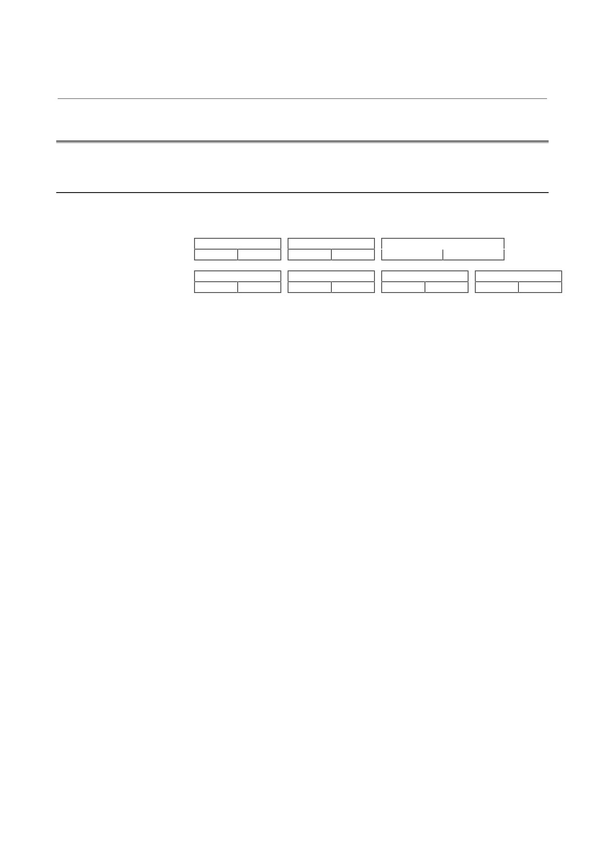
(3) Exchange the command cables according to the diagram here.
When switching the CNC on, do so in an emergency stop state.
→ If the alarm recurs on the same axis, go to (5).
→ If the alarm occurs on the other axis, go to (4).
CNC
Servo amplifier
Alarmed axis
L-axis
(L-axis)
Normal axis
(M-axis)
M-axis
Command cable
(4) The servo amplifier is defective.
(5) The module for current conversion in the CNC is defective.
- 132 -
3. TROUBLESHOOTING
B-65165E/02
TROUBLESHOOTING
AND ACTION
3.3
SERVO SOFTWARE
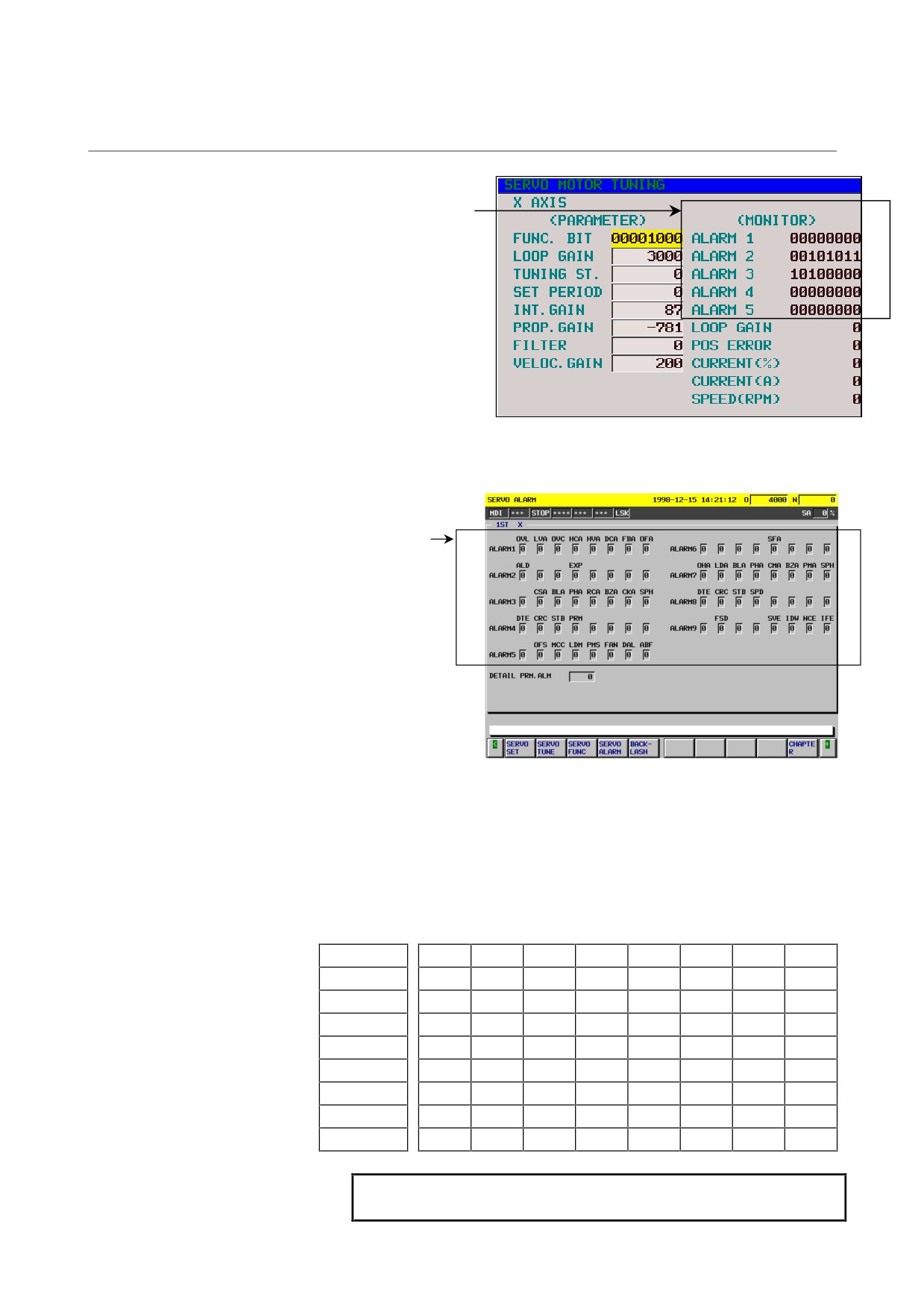
If a servo alarm is issued, an alarm message is output, and details of the
alarm are also displayed on the servo adjustment screen or the
diagnosis screen. Using the alarm identification table given in this
section, determine the alarm, and take a proper action. With a CNC of
the i series, detailed alarm messages are displayed. So, from the
information in the alarm identification table, select a proper action.
3.3.1
Servo Adjustment Screen
Series 0-C
PARAM
Press the
key several times to display the servo setting screen.
PAGE
Pressing the
keys displays the servo screen.
PAGE
If the servo setting screen does not appear, specify the following
parameter, then switch the CNC off and on again:
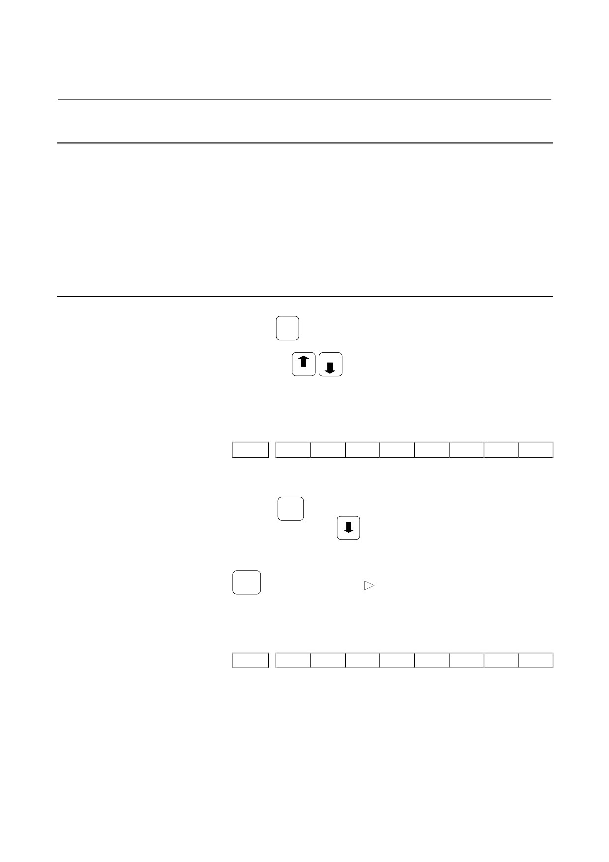
#7
#6
#5
#4
#3
#2
#1
#0
0389
SVS
SVS (#0)=0 (to display the servo setting screen)
Series 15-A/B, 15i
Press the
SERVICE
key several times to cause the servo setting screen to
appear. Then press the
key, and the servo adjustment screen will
appear.
Series 16, 18, 20, 21
SYSTEM
→ [SYSTEM] → [
]
→ [SV-PRM] → [SV-TUN]
If the servo setting screen does not appear, specify the following
parameter, then switch the CNC off and on again.
#7
#6
#5
#4
#3
#2
#1
#0
3111
SVS
SVS (#0)=1 (to display the servo setting screen)
- 133 -
3. TROUBLESHOOTING
AND ACTION
TROUBLESHOOTING
B-65165E/02
Alarm detail
information
<1>
<2>
<3>
<4>
<5>
Fig. 3.3.1(a) Servo adjustment screen
Alarm detail
information
<1>
<6>
<2>
<7>
<3>
<8>
<4>
<9>
<5>
Fig. 3.3.1(b) Series 15i servo alarm screen
The table below indicates the names of the alarm bits.
Table 3.3.1 List of alarm bit names
#7
#6
#5
#4
#3
#2
#1
#0
<1> Alarm 1
OVL
LVA
OVC
HCA
HVA
DCA
FBA
OFA
<2> Alarm 2
ALD
EXP
<3> Alarm 3
CSA
BLA
PHA
RCA
BZA
CKA
SPH
<4> Alarm 4
DTE
CRC
STB
PRM
<5> Alarm 5
OFS
MCC
LDM
PMS
FAN
DAL
ABF
<6> Alarm 6
SFA
<7> Alarm 7
OHA
LDA
BLA
PHA
CMA
BZA
PMA
SPH
<8> Alarm 8
DTE
CRC
STB
SPD
<9> Alarm 9
FSD
SVE
IDW
NCE
IFE
NOTE
The empty fields do not represent alarm codes.
- 134 -
3. TROUBLESHOOTING
B-65165E/02
TROUBLESHOOTING
AND ACTION
3.3.2
Diagnosis Screen
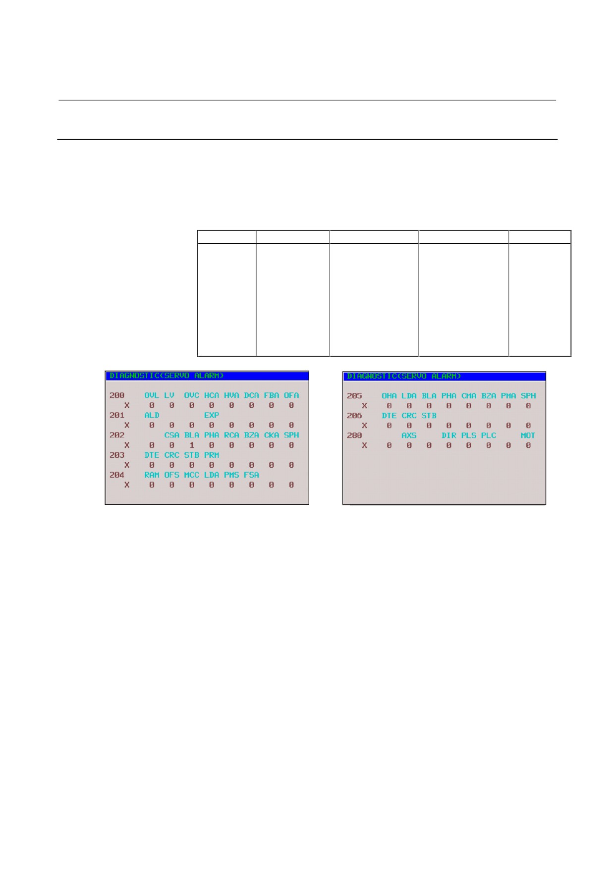
The alarm items of the servo adjustment screen correspond to the
diagnosis screen numbers indicated in the table below.
Table 3.3.2
Correspondence between the servo adjustment screen and
diagnosis screen
Alarm No.
Series 0-C
Series 15-A, B, 15i
Series 16, 18, 20, 21
PowerMate-E
<1> Alarm 1
No 720 to 723
No 3014 + 20(X-1)
No
200
No 2711
<2> Alarm 2
730 to 733
3015 + 20(X-1)
201
2710
<3> Alarm 3
760 to 763
3016 + 20(X-1)
202
2713
<4> Alarm 4
770 to 773
3017 + 20(X-1)
203
2712
<5> Alarm 5
204
2714
<6> Alarm 6
<7> Alarm 7
205
<8> Alarm 8
206
<9> Alarm 9
<1>
<7>
<2>
<8>
<3>
<4>
<5>
Fig. 3.3.2 Series 16i diagnosis screen
- 135 -
3. TROUBLESHOOTING
AND ACTION
TROUBLESHOOTING
B-65165E/02
3.3.3
Overload Alarm (Soft Thermal, OVC)
(Alarm identification method)
#7
#6
#5
#4
#3
#2
#1
#0
<1> Alarm 1
OVL LVA OVC HCA HVA DCA FBA OFA
(Action)
(1) Make sure that the motor is not vibrating.
⇒ If a motor vibrates, the current flowing in it becomes more
than necessary, resulting in an alarm.
(2) Make sure that the power line to the motor is connected correctly.
⇒ If the connection is incorrect, an abnormal current flows in
the motor, resulting in an alarm.
(3) Make sure that the following parameters are set correctly.
⇒ An overload alarm is issued based on the result of calculation
of these parameters. Be sure to set them to the standard values.
For details of the standard values, refer to the parameter
manual (B-65150E).
1877
8x62
Overload protection coefficient (OVC1)
2062
1062
1878
8x63
Overload protection coefficient (OVC2)
2063
1063
1893
8x65
Overload protection coefficient (OVCLMT)
2065
1065
(4) Attach the check board (A06B-6071-K290) to connector JX5 to
measure the waveform of the actual current (IR and IS) of the
servo amplifier module. Start the motor and measure the actual
current (IR and IS).
⇒ If the actual current exceeds 1.4 times the rated current, the
constant for the acceleration/deceleration duration is too
small, or the load on the machine is too heavy for the capacity
of the motor.
⇒ If the actual current exceeds 1.4 times the rated current during
normal operation, the load on the machine is too heavy for the
capacity of the motor.
- 136 -
3. TROUBLESHOOTING
B-65165E/02
TROUBLESHOOTING
AND ACTION
3.3.4
Feedback Disconnected Alarm
(Alarm identification method)
#7
#6
#5
#4
#3
#2
#1
#0
<1> Alarm 1
OVL LVA OVC HCA HVA DCA FBA OFA
<2> Alarm 2
ALD
EXP
<6> Alarm 6
SFA
FBA ALD EXP SFA
Alarm description
Action
1
1
1
0
Hard disconnection (separate phase A/B)
1
1
0
0
0
Soft disconnection (closed loop)
2
1
0
0
1
Soft disconnection (α pulse coder)
3
(Action)
Action 1:
This alarm is issued when a separate phase A/B scale is
used. Check if the phase A/B detector is connected
correctly.
Action 2:
This alarm is issued when the position feedback pulse
variation is small relative to the velocity feedback pulse
variation. This means that this alarm is not issued when a
semi-full is used. Check if the separate detector outputs
position feedback pulses correctly. If position feedback
pulses are output correctly, it is considered that the motor
alone is rotating in the reverse direction at the start of
machine operation because of a large backlash between the
motor position and scale position.
#7
#6
#5
#4
#3
#2
#1
#0
1808
8X03
TGAL
2003
1003
TGAL (#1)
1: Uses the parameter for the soft disconnection alarm
detection level.
1892
8X64
Soft disconnection alarm level
2064
1064
Standard setting
4: Alarm issued for a 1/8 rotation of the motor.
Increase this value.
Action 3:
This alarm is issued when synchronization between the
absolute position data sent from the built-in pulse coder and
phase data is lost. Turn off the power to the CNC, then
detach the pulse coder cable then attach it again. If this
alarm is still issued, replace the pulse coder.
- 137 -
3. TROUBLESHOOTING
AND ACTION
TROUBLESHOOTING
B-65165E/02
3.3.5
Overheat Alarm
(Alarm identification method)
#7
#6
#5
#4
#3
#2
#1
#0
<1> Alarm 1
OVL LVA OVC HCA HVA DCA FBA OFA
<2> Alarm 2
ALD
EXP
OVL
ALD
EXP
Alarm description
Action
1
1
0
Motor overheat
1
1
0
0
Amplifier overheat
1
(Action)
Action 1: If this alarm is issued after a long-time of continuous
operation, it is considered that the motor and amplifier are
overheated. Stop operation for a while, then make a check.
If this alarm is still issued after the power is off for about 10
minutes then is turned on again, the thermostat is
considered to be faulty. If this alarm is issued intermittently,
increase the time constant or increase stop time in the
program to suppress the rise in temperature.
3.3.6
Invalid Servo Parameter Setting Alarm
The invalid servo parameter setting alarm is issued when a setting out
of the specifiable range is specified, or an overflow has occurred in an
internal calculation. When an invalid parameter is detected on the
servo side, alarm 4 #4 (PRM) = 1 results.
(Alarm identification method)
#7
#6
#5
#4
#3
#2
#1
#0
<4> Alarm 4
DTE CRC STB PRM
For details and action required when the invalid servo parameter setting
alarm is issued on the servo side, refer to the parameter manual (B-
65150E) edition 4 and up.
(Reference information)
Method of checking details of an invalid parameter detected on the
servo side
(For Series 15i)
A number is indicated in the item "Details of invalid parameter" on
the servo alarm screen (Fig. 3.3.1(b)).
(For Series 16i, 18i, 21i, and Power Mate i)
A number is indicated in No. 352 of the diagnosis screen.
- 138 -
3. TROUBLESHOOTING
B-65165E/02
TROUBLESHOOTING
AND ACTION
3.3.7
Alarms Related to Pulse Coder and Separate Serial Detector
(Bits for alarm identification)
#7
#6
#5
#4
#3
#2
#1
#0
<1> Alarm 1
OVL LVA OVC HCA HVA DCA FBA OFA
<2> Alarm 2
ALD
EXP
<3> Alarm 3
CSA BLA PHA RCA BZA CKA SPH
<4> Alarm 4
DTE CRC STB PRM
<5> Alarm 5
OFS MCC LDM PMS FAN DAL ABF
<6> Alarm 6
SFA
<7> Alarm 7
OHA LDA BLA PHA CMA BZA PMA SPH
<8> Alarm 8
DTE CRC STB SPD
<9> Alarm 9
FSD
SVE IDW NCE
IFE
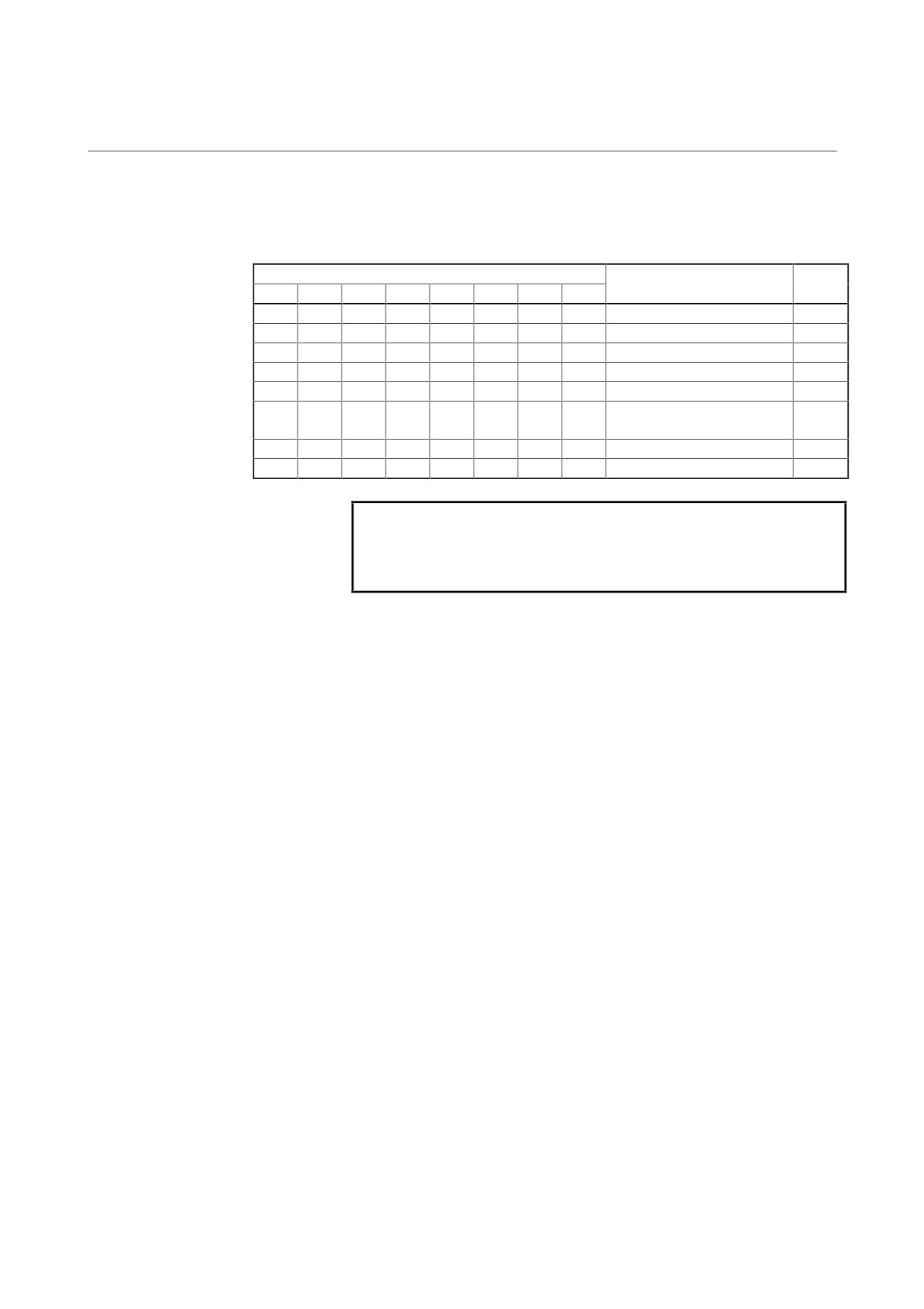
(1) For a built-in pulse coder
An alarm is determined from the bits of alarms 1, 2, 3, and 5. The
table below indicates the meaning of each bit.
Alarm 3
Alarm 5
1
Alarm 2
Alarm description
Action
CSA
BLA
PHA RCA BZA
CKA SPH LDM PMA FBA ALD EXP
1
Soft phase alarm
2
1
Clock alarm (serial A)
1
Zero battery voltage
1
1
0
0
0
Speed error (serial A)
1
1
1
0
Count error alarm (α pulse coder)
2
1
Phase alarm (serial A)
2
1
Battery voltage decrease (warning)
1
1
Checksum alarm (serial A)
1
Pulse error alarm (α pulse coder)
1
LED error alarm (α pulse coder)
NOTE
An alarm for which no action number is given is
considered to be caused by a pulse coder failure.
Replace the pulse coder.
- 139 -
3. TROUBLESHOOTING
AND ACTION
TROUBLESHOOTING
B-65165E/02
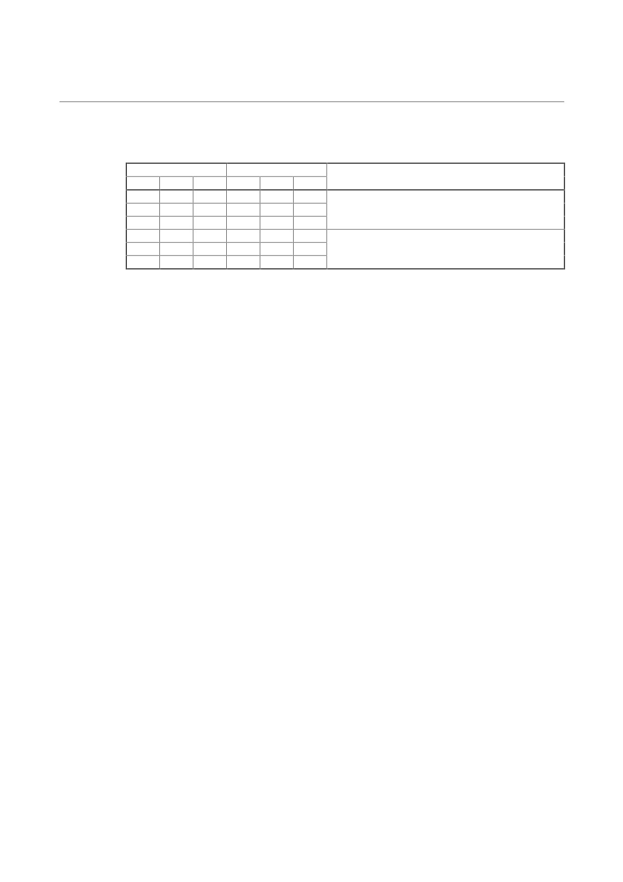
(2) For a separate serial detector
An alarm is determined from the bits of alarm 7. The table below
indicates the meaning of each bit.
Alarm 7
Alarm description
Action
OHA
LDA
BLA
PHA
CMA
BZA
PMA
SPH
1
Soft phase alarm
2
1
Pulse error alarm
1
Zero battery voltage
1
1
Count error alarm
2
1
Phase alarm
2
Battery voltage decrease
1
1
(warning)
1
LED error alarm
1
Separate detector alarm
NOTE
An alarm for which no action number is given is
considered to be caused by a detector failure.
Replace the detector.
(Action)
Action 1: Battery-related alarms
Check if a battery is connected. When the power is turned
on for the first time after a battery is connected, the zero
battery voltage alarm is issued. In such a case, turn off the
power, then turn on the power again. If the alarm is still
issued, check the battery voltage. If the battery voltage
decrease alarm is issued, check the voltage, and replace the
battery as required.
Action 2: Alarms that may be issued for noise
If an alarm is issued intermittently or after emergency stop
cancellation, noise is probably the cause. So, provide noise
protection. If the same alarm is still issued after noise
protection is provided, replace the detector.
- 140 -
3. TROUBLESHOOTING
B-65165E/02
TROUBLESHOOTING
AND ACTION
(3) Alarms related to serial communication
An alarm is determined from the bits of alarms 4 and 8.
Alarm 4
Alarm 8
Alarm description
DTE
CRC
STB
DTE
CRC
STB
1
1
Serial pulse coder communication alarm
1
1
1
Separate serial pulse coder communication alarm
1
Action: Serial communication is not performed correctly. Check if
the cable is connected correctly and is not broken. If CRC
or STB is issued, noise may be the cause. So, provide noise
protection. If CRC or STB is always issued after the power
is turned on, the pulse coder or amplifier control board (i
series) or the pulse module (i series) may be faulty.
- 141 -
3. TROUBLESHOOTING
AND ACTION
TROUBLESHOOTING
B-65165E/02
3.3.8
Other Alarms
(Alarm identification method)
#7
#6
#5
#4
#3
#2
#1
#0
<5> Alarm 5
OFS
MCC
LDM
PMS
FAN
DAL
ABF
OFS
DAL
ABF
Alarm description
Action
1
Feedback mismatch alarm
1
1
Excessive semi-full error alarm
2
1
Current offset error alarm
3
(Action)
Action 1: This alarm is issued when the move direction of the position
detector is opposite to the move direction of the speed
detector. Check the rotation direction of the separate
detector. If the rotation direction of the separate detector is
opposite to the rotation direction of the motor, take the
following action:
For a phase A/B detector: Reverse the connections of A and
A.
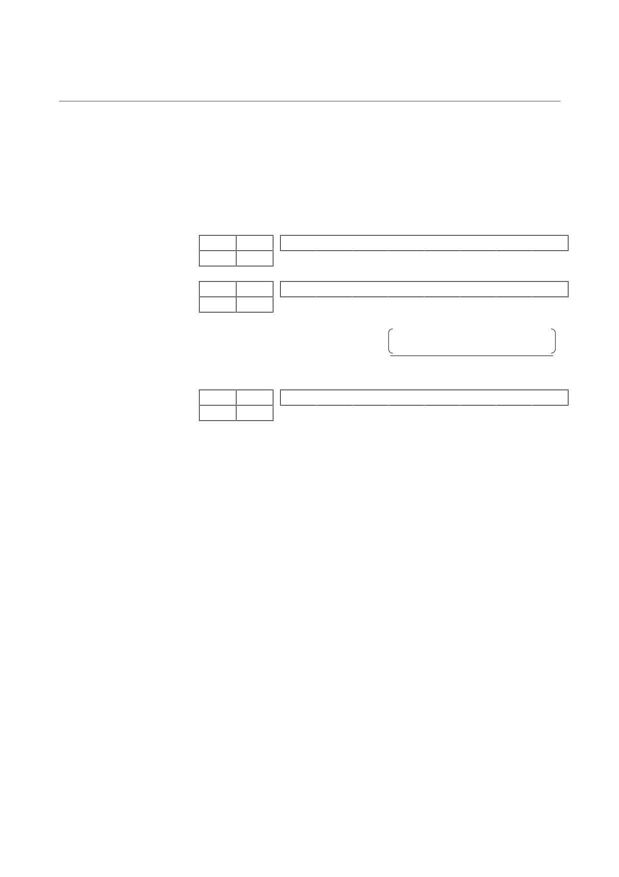
For a serial detector: Reverse the setting of the signal
direction of the separate detector.
#7
#6
#5
#4
#3
#2
#1
#0
1960
-
RVRSE
2018
-
RVRSE (#0)
Reverses the signal direction of the separate detector.
0: Does not reverse the signal direction of the separate detector.
1: Reverses the signal direction of the separate detector.
If a large distortion exists between the motor and separate detector, this
alarm may be issued in the case of abrupt acceleration/ deceleration. In
such a case, modify the detection level.
#7
#6
#5
#4
#3
#2
#1
#0
1741
-
RNLV
2201
-
RNLV (#1)
Modifies the feedback mismatch alarm detection level.
1: Detected with 1000 min-1 or more
0: Detected with 600 min-1 or more
- 142 -
3. TROUBLESHOOTING
B-65165E/02
TROUBLESHOOTING
AND ACTION
Action 2: This alarm is issued when the difference between the motor
position and separate detector position exceeds the
excessive semi-full error level. Check if the conversion
efficient for dual position feedback is set correctly. If the
conversion efficient is set correctly, increase the alarm level.
If this alarm is still issued after the level is modified, check
the connection direction of the scale.
1971
-
Dual position feedback conversion coefficient (numerator)
2078
-
1972
-
Dual position feedback conversion coefficient (denominator)
2079
-
Number of feedback pulses per motor
revolution (detection unit)
Conversion coefficient =
1,000,000
1729
-
Dual position feedback semi-full error level
2118
-
[Setting]
Detection unit. When 0 is set, no detection is made.
Action 3: The current offset value of the current detector (equivalent
to the current value in the emergency stop state) is
abnormally high. If this alarm is still issued after the power
is turned off then back on, the current detector is faulty. For
the i series, replace the control board of the amplifier. For
series other than the i series, replace the servo-related
modules on the CNC.
- 143 -
3. TROUBLESHOOTING
AND ACTION
TROUBLESHOOTING
B-65165E/02
3.4
SPINDLE AMPLIFIER MODULE
This section uses the following format for describing parameter
numbers:
FS0
FS15i
FS16i/16, PM-D/F
Description
6582
3082
4082
Setting of acceleration/deceleration
time
The items of FS15i cover FS15. For a parameter number of FS15
different from FS15i, the item is described separately.
FS18i, 20i, 21i, PMi-D, 18, 20, and 21 are covered by the items of
FS16i/16.
3.4.1
α Series and α (HV) Series Spindle Amplifier Module
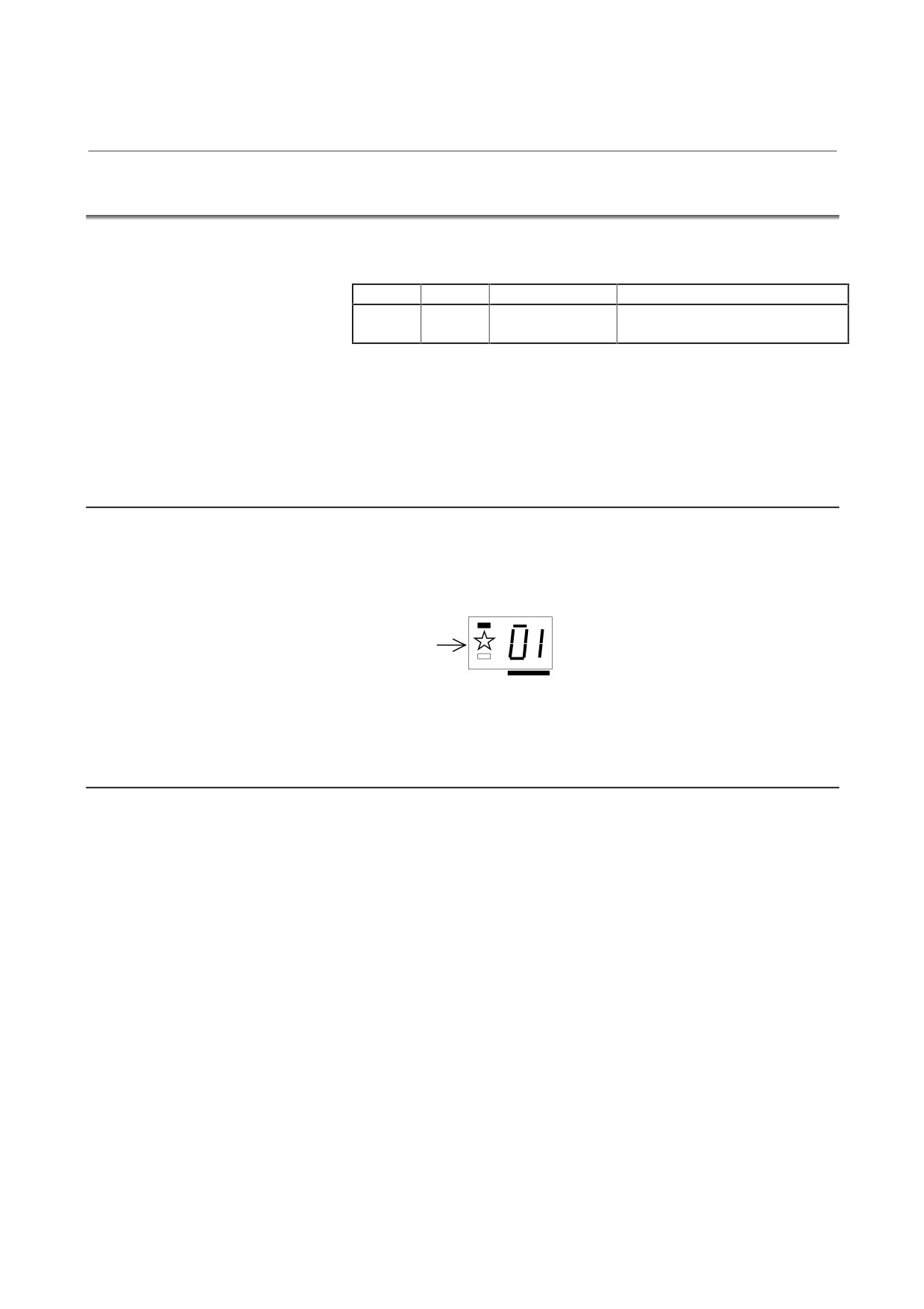
If an alarm occurs in the spindle amplifier module, the ALM LED
lights red in the STATUS display, and the two-digit 7-segment LEDs
indicate the alarm code.
status
The ALM LED
lights red.
Alarm code A0, A1, 01 or above is indicated.
3.4.1.1 Alarm codes A, A0 to A4, and other Ax (x for representing an
arbitrary number)
A, A0
: The SPM control program is not operating.
A1, A2, Ax : An error was detected in SPM control program
processing.
A3
: An error was detected in the clock of the SPM control
printed circuit board.
A4
: A parity error was detected in the SRAM on the SPM
control printed circuit board.
(1) If an alarm is issued when the power to the PSM is turned on
(a) The ROM is not installed correctly, no ROM is installed, or
the ROM specification is incorrect
If the ROM on the SPM control printed circuit board is once
replaced, check the following:
<1> Installation direction
<2> Occurrence of a bent lead and so forth
<3> Matching of the ROM series with the unit. Check
Subsection 2.2.3 of Part I.
(b) Printed circuit board failure
Replace the SPM or SPM control printed circuit board.
- 144 -
3. TROUBLESHOOTING
B-65165E/02
TROUBLESHOOTING
AND ACTION
(2) If an alarm is issued during motor activation
(a) Influence of noise
Referring to Chapter 5, "Installation," of "FANUC SERVO
AMPLIFIER α series Descriptions (B-65162E)," check the
GND-related wiring. If the signal cable of the spindle sensor
is bundled with the power line of the servo motor, separate
them from each other.
3.4.1.2
Alarm code 01
The inside temperature of the motor is higher than the specified
temperature.
(1)
If this alarm is issued during cutting (the motor temperature is
high)
(a) Check the cooling state of the motor.
<1> If the cooling fan of the spindle motor is stopped, check
the power supply of the cooling fan. If the cooling fan
is still inoperative, replace it with a new one.
<2> When a liquid-cooled motor is used, check the cooling
system.
<3> When the ambient temperature of the spindle motor is
higher than the specified temperature, lower the
ambient temperature to satisfy the specification.
(b) If this alarm is issued even when the load meter fluctuates in
a limited range, check the short-period rating. If the
specified value is exceeded, reduce the load.
(2)
If this alarm is issued under a light load (the motor temperature is
high)
(a) When the frequency of acceleration/deceleration is too high
Set such a use condition that the average including output at
acceleration/deceleration does not exceed the continuous
rating.
(b) The parameters specific to the motor are not set correctly.
Refer to "FANUC AC SPINDLE MOTOR α series
Parameter Manual (B-65160E)."
(3)
If this alarm is issued when the motor temperature is low
(a) The spindle sensor feedback cable is faulty.
Replace the cable.
(b) The SPM control printed circuit board is faulty.
Replace the SPM control printed circuit board or SPM.
(c) The motor (internal thermostat) is faulty.
Replace the motor.
- 145 -
3. TROUBLESHOOTING
AND ACTION
TROUBLESHOOTING
B-65165E/02
3.4.1.3
Alarm code 02
The actual motor speed is largely deviated from the commanded speed.
(1) If this alarm is issued during motor acceleration
(a) The parameter setting of acceleration/deceleration time is
incorrect.
In the following parameter, set the value equivalent to the
spindle inertia plus some margin:
FS0
FS15i
FS16i/16, PM-D/F
Description
6582
3082
4082
Setting of acceleration/deceleration
time
(b) The parameter for the speed detector is not set correctly.
Referring to "FANUC AC SPINDLE MOTOR α series
Parameter Manual (B-65160E)," set a correct value.
(2) If this alarm is issued during cutting
(a) The cutting load has exceeded the motor output power.
Check the load meter indication, and review the use
condition.
(b) The parameters for output restriction are not set correctly.
Check that the settings of the following parameters satisfy
the machine and motor specifications:
FS0
FS15i
FS16i/16, PM-D/F
Description
6528
3028
4028
Output restriction pattern setting
6529
3029
4029
Output restriction value
(c) The parameters specific to the motor are not correctly.
Refer to "FANUC AC SPINDLE MOTOR α series
Parameter Manual (B-65160E)."
- 146 -
3. TROUBLESHOOTING
B-65165E/02
TROUBLESHOOTING
AND ACTION
3.4.1.4
Alarm code 03
The fuse of the DC link has blown.
(The voltage at the DC link is
insufficient.) This alarm is checked when emergency stop is cancelled.
(1) If this alarm is issued during spindle operation (rotation)
The fuse of the DC link inside the SPM has probably blown. So,
replace the SPM. This alarm may be caused by the following:
<1> Power line short-circuited to ground
<2> Motor winding short-circuited to ground
<3> IGBT or IPM module failure
(2) If the PSM input magnetic contactor is once turned on and is
turned off with this alarm when emergency stop is cancelled or the
CNC is started (When two spindles are connected, the magnetic
contactor may not be turned off.)
(a) The DC link wire is not connected.
Check the DC link (TB1) wiring for errors.
(b) A cable is faulty.
Pin 9 of the interface cable (JX1B-JX1A) between the PSM
and SPM may be short-circuited to 0V. Replace the cable.
(c) The fuse of the DC link inside the SPM has blown.
Replace the SPM.
3.4.1.5 Alarm code 04
It is detected that the 3-phase input to the main circuit of the PSM has
an open phase.
(1) If the PSM indicates alarm code 6
Troubleshoot according to the description of alarm code
6
provided in Section 3.1 of Part II.
(2) If the PSM indicates no alarm
(a) A cable is faulty.
The connection cable between the PSM (JX1B) and SPM
(JX1A) is faulty. Replace the cable.
(b) The SPM is faulty.
Replace the SPM or SPM control printed circuit board.
- 147 -
3. TROUBLESHOOTING
AND ACTION
TROUBLESHOOTING
B-65165E/02
3.4.1.6 Alarm code 07
The motor rotates at a speed exceeding 115% (standard setting) of the
maximum allowable speed.
(1) If this alarm is issued during spindle synchronization
If the activation (SFR, SRV) of the motor on one side is turned off
then back on in the spindle synchronization mode, the spindle
motor is accelerated to correct a position error built up during the
period, thus causing this alarm. Modify the ladder so that SFR
and SRV are not turned off in the spindle synchronization mode.
(2) If this alarm is issued while the motor is stopped
(a) The connection cable of the spindle sensor is faulty.
Check if the cable of the spindle sensor built into the motor
(BZ sensor when a built-in motor is used) is disconnected,
and replace the cable as required.
(b) The spindle sensor built into the motor is not adjusted
correctly.
Adjust the sensor according to Subsection 4.3.4 of Part I.
3.4.1.7 Alarm code 09
The temperature of the heat sink of the SPM main circuit has risen to
the set value. This alarm is issued for SPM-15 and up or SPM-15HV
and later. With SPM-2.2 to SPM-11 and SPM-11HV, however, alarm
code 12 is issued for the same cause.
(1) If this alarm is issued during cutting (the heat sink temperature is
high)
(a) If this alarm is issued when the load meter reads a value
below the continuous rating of the amplifier, check the
cooling state of the heat sink.
<1> If the cooling fan is stopped, check the power supply
(connector CX1A/B). If the cooling fan is still
inoperative, replace the SPM with a new one.
<2> When the ambient temperature is higher than the
specified temperature, lower the ambient temperature
to satisfy the specification.
(b) When this alarm is issued because the load meter reads a
value above the continuous rating of the amplifier, improve
the use method.
- 148 -
3. TROUBLESHOOTING
B-65165E/02
TROUBLESHOOTING
AND ACTION
(c) When the heat sink on the back of the amplifier is too dirty,
clean the heat sink, for example, by blowing air. Consider
the use of a structure that prevents the heat sink from being
directly exposed to coolant.
(2) If this alarm is issued under a light load (the heat sink temperature
is high)
(a) When the frequency of acceleration/deceleration is too high
Set such a use condition that the average including output at
acceleration/deceleration does not exceed the continuous
rating.
(b) The parameters specific to the motor are not set correctly.
Refer to "FANUC AC SPINDLE MOTOR α series
Parameter Manual (B-65160E)."
(3) If this alarm is issued when the heat sink temperature is low
Replace the SPM.
3.4.1.8 Alarm code 11
The PSM detected that the DC link voltage was excessively high.
(1) If the PSM indicates alarm code 7
Troubleshoot according to the description of alarm code
7
provided in Section 3.1 of Part II.
(2) If the PSM indicates no alarm
(a) A cable is faulty.
The connection cable between the PSM (JX1B) and SPM
(JX1A) is faulty. Replace the cable.
(b) The SPM is faulty.
Replace the SPM or SPM control printed circuit board.
- 149 -
3. TROUBLESHOOTING
AND ACTION
TROUBLESHOOTING
B-65165E/02
3.4.1.9
Alarm code 12
An excessively large current flowed into the DC link of the main
circuit.
With SPM-2.2 to SPM-11 and SPM-11HV, this alarm indicates that the
power module (IPM) of the main circuit detected an error such as an
excessive load, overcurrent, or low control supply voltage.
(1)
If this alarm is issued on SPM-2.2 to SPM-11 and SPM-11HV
Check alarm code 09 as well.
(2)
If this alarm is issued immediately after a spindle rotation
command is specified
(a) The motor power line is faulty.
Check for a short circuit between motor power lines and
short-circuit to ground, and replace the power line as
required.
(b) The motor winding has an insulation failure.
If the motor is short-circuited to ground, replace the motor.
(c) The parameters specific to the motor are not set correctly.
Refer to "FANUC AC SPINDLE MOTOR α series
Parameter Manual (B-65160E)."
(d) The SPM is faulty.
A power element (IGBT, IPM) may be destroyed. Replace
the SPM.
(3)
If this alarm is issued during spindle rotation
(a) A power element is destroyed.
A power element (IGBT, IPM) may be destroyed. Replace
the SPM.
If the amplifier setting condition is not satisfied, or cooling is
insufficient because the heat sink is dirty, the power
elements may be destroyed.
When the heat sink on the back of the amplifier is too dirty,
clean the heat sink, for example, by blowing air. Consider
the use of a structure that prevents the heat sink from being
directly exposed to coolant.
For the setting condition, refer to "FANUC SERVO
AMPLIFIER α series Descriptions (B-65162E)."
(b) The parameters specific to the motor are not set correctly.
Referring to "FANUC AC SPINDLE MOTOR α series
Parameter Manual
(B-65160E)," check the parameters
specific to the motor.
(c) Speed sensor signal error
Check the spindle sensor signal waveform according to
Subsection 4.3.4 of Part I. If an error is found, make an
adjustment or replace the detector as required.
- 150 -
3. TROUBLESHOOTING
B-65165E/02
TROUBLESHOOTING
AND ACTION
3.4.1.10 Alarm code 13
The memory inside the CPU is faulty. A check is made when the power
is turned on.
If this alarm is issued, replace the SPM or SPM control printed circuit
board.
3.4.1.11
Alarm code 15
In output switching control or spindle switching control, the switching
operation sequence was not executed correctly.
This alarm is issued if one second or more elapses from the transition of
a switch request signal (SPSL or RSL) until a power line state check
signal (MCFN, MFNHG, RCH, or RCHHG) makes a transition.
Troubleshooting when this alarm is issued
(a) The magnetic contactor
(switch unit) for power line
switching is faulty.
If the contact is inoperative, check the power supply of the
magnetic contactor. If the magnetic contactor is still
inoperative, replace the magnetic contactor.
(b) The I/O unit or wiring for checking the contact of the
magnetic contactor is faulty.
If a defect is found in the I/O unit or wiring, replace the I/O
unit or wiring.
(c) The sequence (ladder) is incorrect.
Modify the sequence so that switching is completed within 1
second. For details of the signals, refer to Chapter 10,
"Interface Signals," in "FANUC SERVO AMPLIFIER α series
Descriptions (B-65162E)."
3.4.1.12 Alarm code 16
The memory (RAM) is faulty. A check is made when the power is
turned on.
If this alarm is issued, replace the SPM or SPM control printed circuit
board.
- 151 -
3. TROUBLESHOOTING
AND ACTION
TROUBLESHOOTING
B-65165E/02
3.4.1.13 Alarm codes 19 and 20
The offset voltage of the phase U (alarm code 19) or phase V (alarm
code 20) current detection circuit is excessively high. A check is made
when the power is turned on.
If this alarm is issued, replace the SPM. If this alarm is issued
immediately after the SPM control printed circuit board is replaced,
check the plugging of the connectors (CN1, CN3, and CN4) between
the power unit and SPM control printed circuit board.
3.4.1.14
Alarm code 24
The power to the CNC is turned off. (This symptom does not represent
an error.) Serial communication data transferred between the CNC and
spindle amplifier module contains an error.
Troubleshooting when this alarm is issued
(a) Noise occurring between the CNC and spindle amplifier
module (connected via an electric cable) caused an error in
communication data.
Check the condition for maximum wiring length.
Referring to Chapter 9, "Connection," in "FANUC SERVO
AMPLIFIER α series Descriptions (B-65162E)," check the
condition of electric cable connection.
(b) Noise exercises an influence because a communication cable
is bundled with the power line.
If a communication cable is bundled with the power line for
the motor, separate them from each other.
(c) A cable is faulty.
Replace the cable.
If an optical I/O link adapter is used, the optical link adapter
or optical cable may be faulty.
(d) The SPM is faulty.
Replace the SPM or SPM control printed circuit board.
(e) The CNC is faulty.
Replace the board or module related to the serial spindle.
3.4.1.15 Alarm code 25
Serial communication between the CNC and spindle amplifier module
stopped.
Troubleshoot as in the case of alarm code 24.
- 152 -
3. TROUBLESHOOTING
B-65165E/02
TROUBLESHOOTING
AND ACTION
3.4.1.16
Alarm code 26
The sensor signal (for speed control) for Cs contour control has an
error.
<1> When a high-resolution magnetic pulse coder is used with SPM
TYPE2 (using both of the JY2 and JY5 connectors), the amplitude
of the sensor signal on the high-resolution side (1000 λ) of the
high-resolution magnetic pulse coder built into the motor on the
JY2 side is excessively small.
<2> When a built-in motor is used with SPM TYPE2 (using only the
JY5 connector), the amplitude of the sensor signal on the high-
resolution side (1000 to 3000 λ) of the high-resolution magnetic
pulse coder is excessively small.
<3> When SPM TYPE4 is used, the amplitude of the spindle sensor
(MZ sensor) built into the motor connected to JY2 is excessively
small.
(1)
If this alarm is issued when the motor is deactivated
(a) The setting of a parameter is incorrect.
Referring to "FANUC AC SPINDLE MOTOR α series
Parameter Manual (B-65160E)," check the parameter for
sensor setting.
(b) The sensor is not adjusted correctly, or the cable is
disconnected.
Adjust the sensor signal according to Subsection 4.3.4 of
Part I of this manual. If the signal is not observed, replace
the cable and sensor.
(c) The printed circuit board is faulty.
Replace the SPM or SPM control printed circuit board.
(2)
If this alarm is issued when the cable is moved (as in the case
where the spindle moves)
(a) The connector has a bad contact, or the cable is
disconnected.
The conductor may be broken. Replace the cable. If coolant
has penetrated into the connector, clean the connector.
- 153 -
3. TROUBLESHOOTING
AND ACTION
TROUBLESHOOTING
B-65165E/02
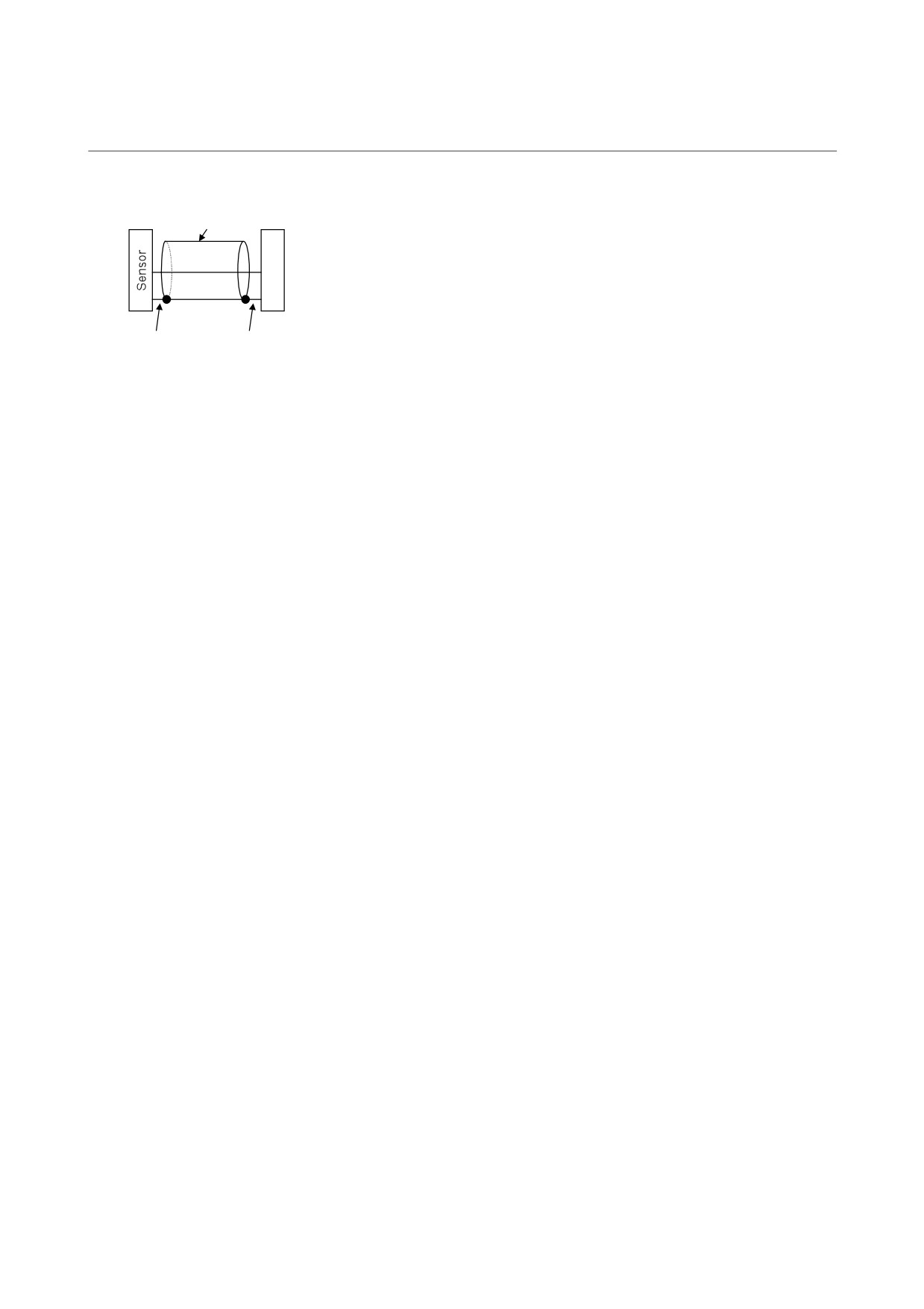
(3) If this alarm is issued when the motor rotates
Shielded cable
(a) The shielding of the cable between the preamplifier or MZ
sensor (for TYPE4) and the SPM is faulty.
S
Referring to Chapter 9, "Connection," in "FANUC SERVO
P
M
AMPLIFIER α series Descriptions (B-65162E)," check the
shielding of the cable.
(b) The signal cable is bundled with the servo motor power line.
The cable is
The cable is
If the cable between the preamplifier or MZ sensor (for
connected to the
connected to
TYPE4) and the SPM is bundled with the servo motor power
pin specified in the
pin 10 on the
specifications on
SPM side.
line, separate them from each other.
the sensor side.
(c) Improve the cable routing between the motor and
preamplifier.
If the cables
(including those within a terminal box)
extending from the motor to the preamplifier are close to the
power line, separate the cables from the power line.
- 154 -
3. TROUBLESHOOTING
B-65165E/02
TROUBLESHOOTING
AND ACTION
3.4.1.17 Alarm code 27
The sensor signal
(position coder signal) for position control is
abnormal.
<1> The signal of the α position coder is disconnected (for all types).
<2> When an MZ or BZ sensor is used with SPM TYPE1 (using the
JY2 connector), the amplitude of the sensor signal is excessively
small.
<3> When a separate built-in sensor is used with SPM TYPE2 (using
the JY2 and JY5 connectors), the amplitude of the spindle sensor
signal on the JY2 side is excessively small.
<4> When a high-resolution magnetic pulse coder is used with SPM
TYPE2 (using the JY2 and JY5 connectors), the amplitude of the
sensor signal on the low-resolution side (128 to 384 λ) on the JY5
side is excessively small.
<5> When SPM TYPE4 is used, the amplitude of the spindle sensor
signal connected to JY5 is excessively small.
(1)
If this alarm is issued when the motor is deactivated
(a) The setting of a parameter is incorrect.
Referring to Chapter 2 of "FANUC AC SPINDLE MOTOR
α series Parameter Manual
(B-65160E)," check the
parameter for sensor setting.
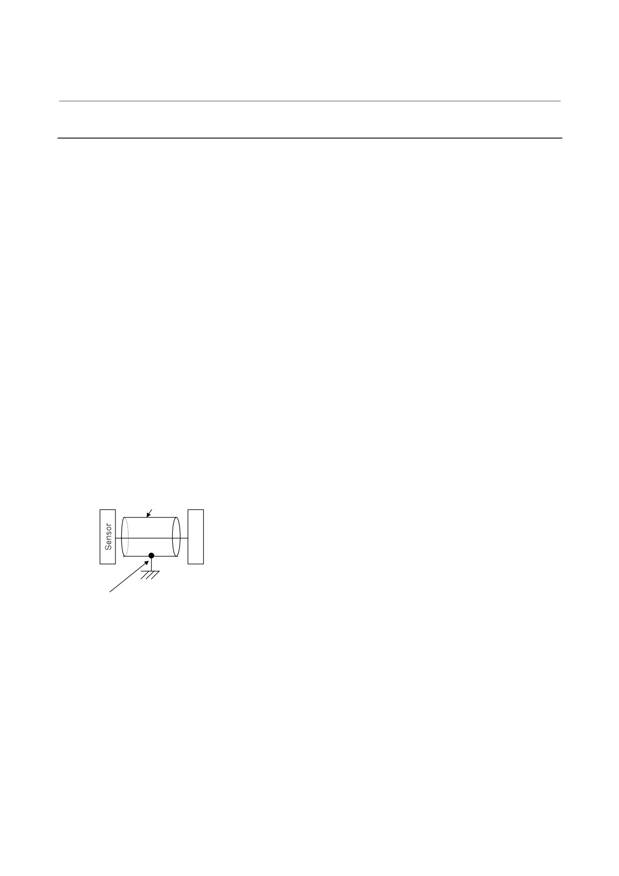
(b) The cable connected to JY4 is disconnected.
(α position
α position coder
coder)
Shielded cable
When the α position coder is used, adjustment is impossible.
Replace the cable.
S
(c) The sensor is not adjusted correctly.
P
M
Adjust the sensor signal according to Subsection 4.3.4 of
Part I of this manual. If the sensor signal cannot be adjusted
correctly, or the sensor signal is not observed, replace the
connection cable and sensor.
Connected to the
frame
(d) The SPM is faulty.
ground via a cable clamp.
Replace the SPM or SPM control printed circuit board.
(2)
If this alarm is issued when the cable is moved (as in the case
where the spindle moves)
(a) The connector has a bad contact, or the cable is
disconnected.
The conductor may be broken. Replace the cable. If coolant
has penetrated into the connector, clean the connector.
- 155 -
3. TROUBLESHOOTING
AND ACTION
TROUBLESHOOTING
B-65165E/02
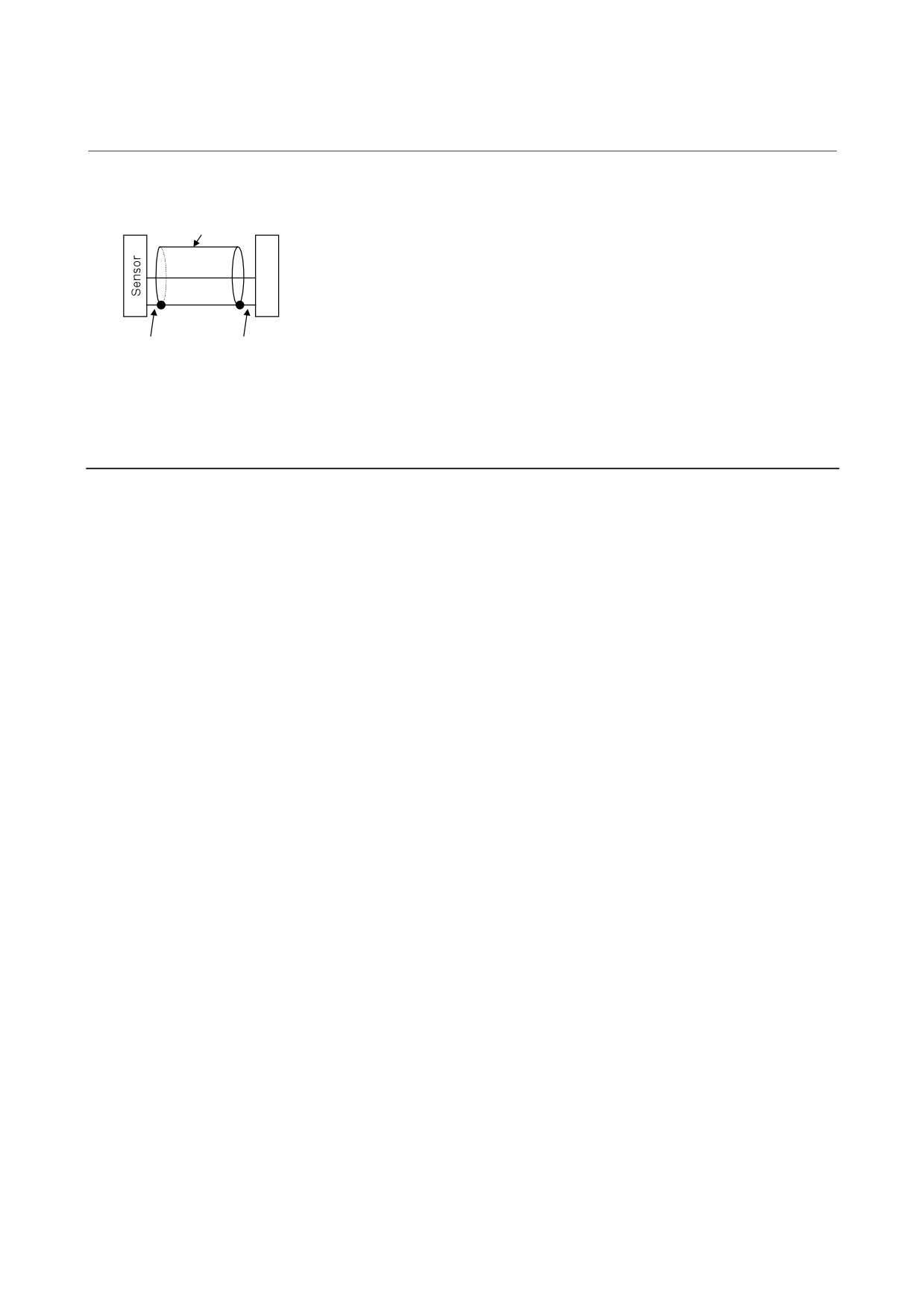
Other sensors
(3) If this alarm is issued when the motor rotates
(a) The shielding of the cable between the sensor and the SPM is
Shielded cable
faulty.
S
Referring to Chapter 9, "Connection," in "FANUC SERVO
P
AMPLIFIER α series Descriptions (B-65162E)," check the
M
shielding of the cable.
(b) The signal cable is bundled with the servo motor power line.
If the cable between the sensor and the SPM is bundled with
The cable is
The cable is
connected to the
connected to
the servo motor power line, separate them from each other.
pin specified in the
pin 10 on the
specifications on
SPM side.
the sensor side.
3.4.1.18 Alarm code 28
The sensor signal (for position control) for Cs contour control is
abnormal.
<1> When a high-resolution magnetic pulse coder is used with SPM
TYPE2 (using both of the JY2 and JY5 connectors), the amplitude
of the sensor signal on the high-resolution side (1000 to 3000 λ) of
the high-resolution magnetic pulse coder on the JY5 side is
excessively small.
<2> When SPM TYPE4 is used, the amplitude of the spindle sensor
(MZ sensor) built into the motor connected to JY5 is excessively
small.
Troubleshoot as in the case of alarm code 26.
- 156 -
3. TROUBLESHOOTING
B-65165E/02
TROUBLESHOOTING
AND ACTION
3.4.1.19
Alarm code 29
An excessive load (standard setting: load meter reading of 9 V) has
been applied continuously for a certain period (standard setting: 30
seconds).
(1)
If this alarm is issued during cutting
Check the load meter, and review the cutting condition.
(2)
If this alarm is issued during a stop
(a) The spindle is locked.
Check the sequence to see if the spindle is locked when a
command for very slow movement is specified or orientation
is specified for the spindle.
(3)
If the spindle does not rotate as specified (the spindle rotates at a
very low speed) and this alarm is issued
(a) The setting of a parameter is incorrect.
Referring to "FANUC AC SPINDLE MOTOR α series
Parameter Manual (B-65160E)," check the parameter for
sensor setting.
(b) The phase sequence of the motor power line is incorrect.
(c) The feedback cable of the motor has a problem.
Check if the phase A/B signals are connected correctly.
(d) The feedback cable of the motor is faulty.
Rotate the motor manually to see if a speed is indicated in the
item of motor speed on the CNC diagnosis screen or on the
spindle check board. If no speed indication is provided,
replace the cable or spindle sensor (or motor).
(4)
If the spindle does not rotate as specified (the spindle does not
rotate at all) and this alarm is issued
(a) The power line is abnormal.
Check if the motor power line is connected normally. If
spindle switching or output switching is performed, check if
the magnetic contactor is on.
(b) The SPM is faulty.
Replace the SPM.
- 157 -