FANUC Alpha Series Motors and Modular Drives. Maintenance Manual (GFZ-65165E/02) - page 4

4. CONFIRMATION OF
THE OPERATION
START-UP PROCEDURE
B-65165E/02
For the SPM type 2
Measurement item
Specification
Measurement method
Adjustment method
Vpp
0.86 to 1.20 Vp-p
Adjust potentiometers A3G and B3G
on the preamplifier.
Vpp2
1.20 to 1.51 Vp-p
Adjust potentiometers A1G and B1G
on the preamplifier.
Voffs
2.5 V ±24 mV
Use the DC range of a digital
Adjust potentiometers A3O and B3O
voltmeter.
on the preamplifier.
Voffs2
2.5 V ±15 mV
Use the DC range of a digital
Adjust potentiometers A1O and B1O
voltmeter.
on the preamplifier.
NOTE
Adjust the one-rotation signal while checking the
waveform on the preamplifier.
- 66 -

4. CONFIRMATION OF
B-65165E/02
START-UP PROCEDURE
THE OPERATION
4.3.5
Spindle Check Board
When connecting the check board, you can:
<1> Observe signal waveforms.
<2> Observe internal data.
4.3.5.1
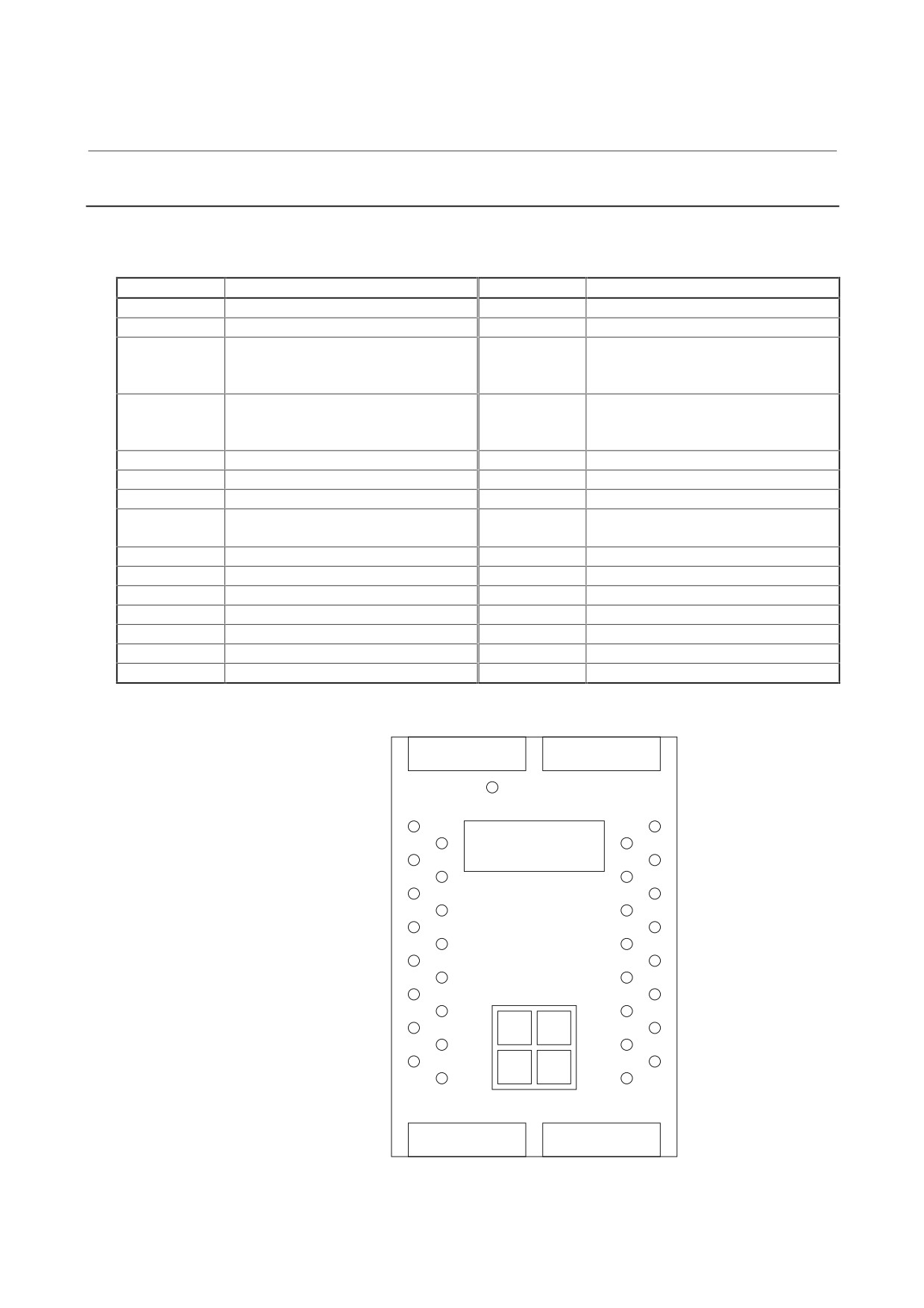
Spindle check board specifications
There are two types of spindle check boards: Check boards for the α
series and for the D series. These types of check boards are not
compatible. Select a spindle check board according to the drawing
number of the SPM used.
Items that vary depending on the type of check board are described
separately by indicating the printed circuit board drawing numbers of
check boards.
Table 4.3.5.1 Spindle check board specifications
Drawing No. of
Specification
Applicable SPM
printed circuit board
A06B-6078-H001
A20B-2001-0830
α series (all series after CE-marked products, and part
of series before CE-marked products)
TYPE1, TYPE4
A06B-6078-H102#H500, -H106#H500, -H111#H500
A06B-6078-H202#H500, -H206#H500, -H211#H500
A06B-6088-H2**#H500, H1**#H500
A06B-6092-H2**#H500, H1**#H500
A06B-6102-H2**#H520, H1**#H520
A06B-6104-H2**#H520, H1**#H520
TYPE2
A06B-6078-H302#H500, -H306#H500, -H311#H500
A06B-6088-H3**#H500
A06B-6092-H3**#H500
TYPE3
A06B-6088-H4**#H500
αC series
A06B-6082-Hxxx#H510, 511, 512
A06B-6072-H051
A20B-1005-0740
α series (part of series before CE-marked products)
TYPE1
A06B-6078-H215#H500, -H222#H500, -H226#H500,
-H230#H500
TYPE2
A06B-6078-H315#H500, -H322#H500, -H326#H500,
-H330#H500
TYPE3
A06B-6078-H411#H500, -H415#H500, -H422#H500,
-H426#H500, -H430#H500
D series (all series)
- 67 -
4. CONFIRMATION OF
THE OPERATION
START-UP PROCEDURE
B-65165E/02
4.3.5.2
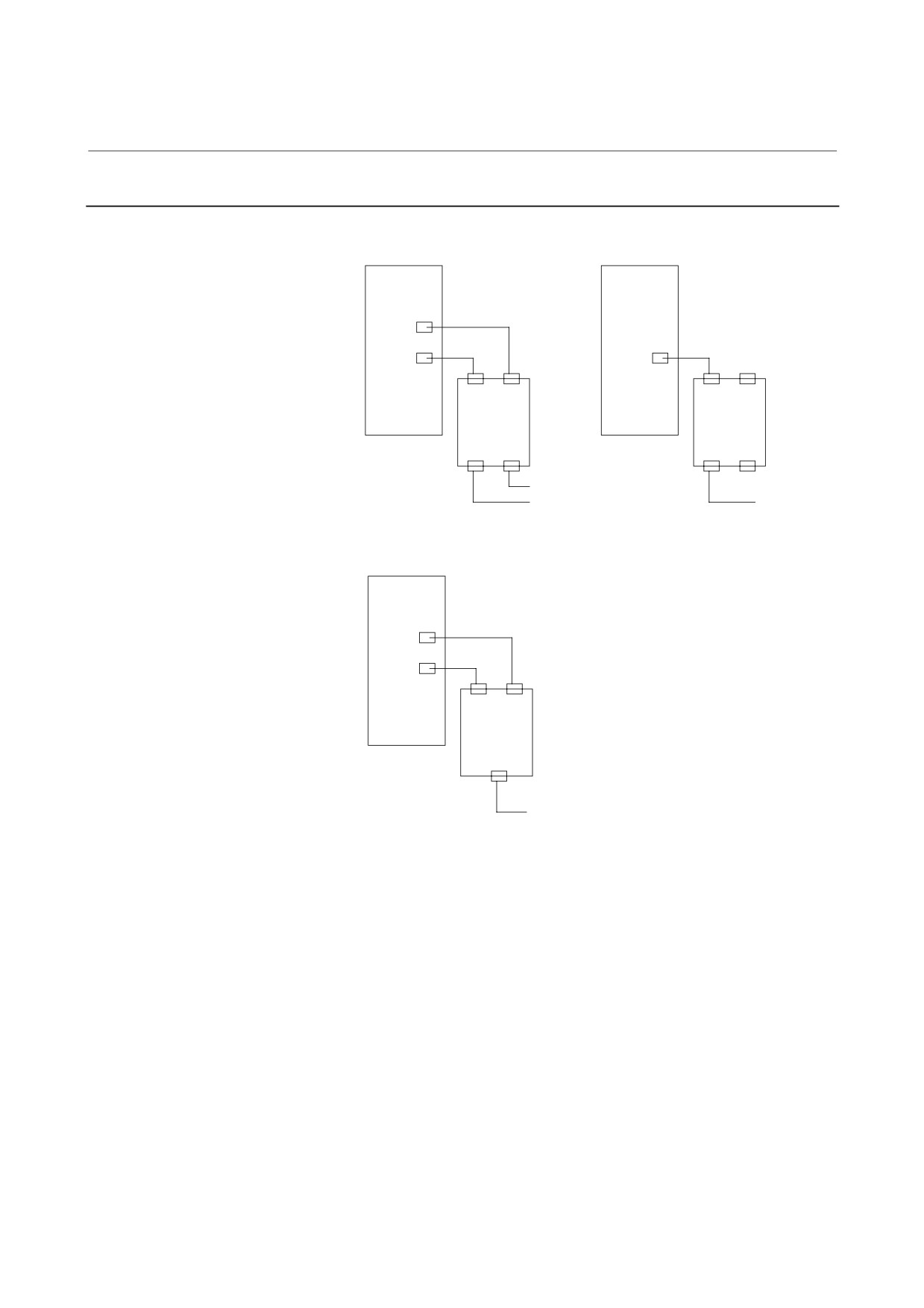
Check board connection
(1) A06B-6078-H001 (A20B-2001-0830)
SPM
SPMC
SPM-HV
JX4
JY1
JY1
Spindle check
Spindle check
JY1A JX4A
JY1A JX4A
board
board
A20B-2001-0830
A20B-2001-0830
JY1B JX4B
JY1B JX4B
Output equivalent to JX4
Output equivalent
Output equivalent to JY1
to JY1
(2) A06B-6072-H051 (A20B-1005-0740)
SPM
JX4
JY1
Spindle check
JY1A JX4A
board
A20B-1005-0740
JY1B
Output equivalent
to JY1
- 68 -
4. CONFIRMATION OF
B-65165E/02
START-UP PROCEDURE
THE OPERATION
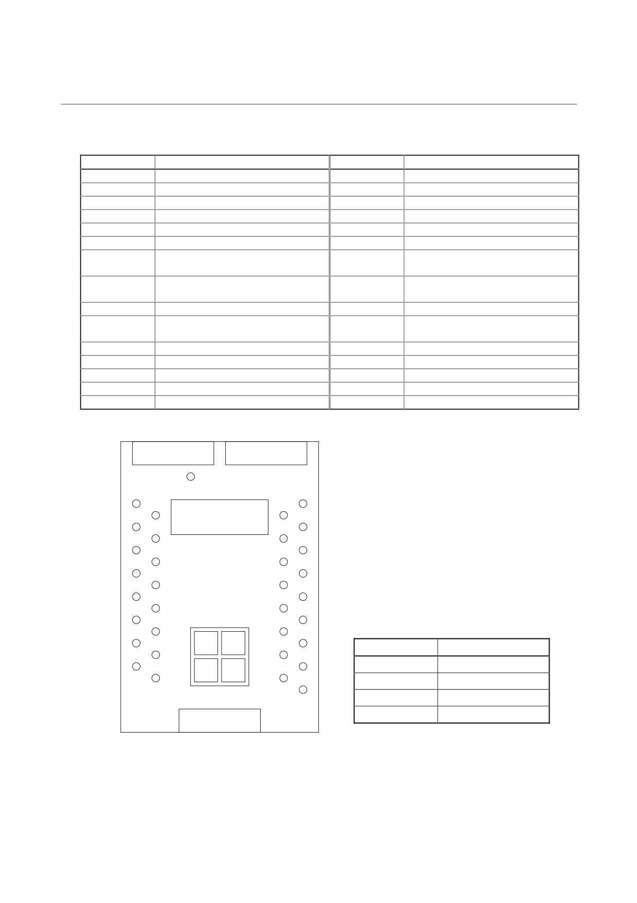
4.3.5.3 Check terminal output signals
(1) A06B-6078-H001
(A20B-2001-0830) check terminal
output
signals
Check terminal
Signal name
Check terminal
Signal name
LM
Load meter signal
PA1
Phase A sine wave signal 1
SM
Speed meter signal
PB1
Phase B sine wave signal 1
CH1
Analog output for internal data
PS1
Phase Z sine wave signal 1
observation
(Phase U current: IU. See 4.3.6.8 (3).)
CH2
Analog output for internal data
PA2
Phase A sine wave signal 2
observation
(Motor speed TSA: 1638 min-1/V)
CH1D
Output for internal data bit observation
PB2
Phase B sine wave signal 2
CH2D
Output for internal data bit observation
PS2
Phase Z sine wave signal 2
VRM
Sensor reference voltage
PA3
Phase A sine wave signal 3
LSA1
Magnetic sensor output LSA signal
PB3
Phase B sine wave signal 3
(main)
EXTSC1
External one-rotation signal (main)
PA4
Phase A sine wave signal 4
LSA2
Magnetic sensor output LSA signal (sub)
PB4
Phase B sine wave signal 4
EXTSC2
External one-rotation signal (sub)
OVR2
Analog override command
PAD
Phase A of position coder signal output
15V
+15 VDC power check
PBD
Phase B of position coder signal output
5V
+5 VDC power check
PSD
Phase Z of position coder signal output
-15V
-15 VDC power check
GND
0 V
Check terminal arrangement
PIL
LM
CH1
Display
LSA2
LSA1
SM
CH1D
EXTSC2
EXTSC1
VRM
CH2
PAD
CH2D
0V
0V
PBD
PA3
PA2
Operation
PA1
PSD
buttons
PB3
PB2
PB1
5V
MODE
UP
PA4
PS2
PS1
15V
DATA
PB4
SET
DOWN
0V
0V
-15V
OVR2
- 69 -
4. CONFIRMATION OF
THE OPERATION
START-UP PROCEDURE
B-65165E/02
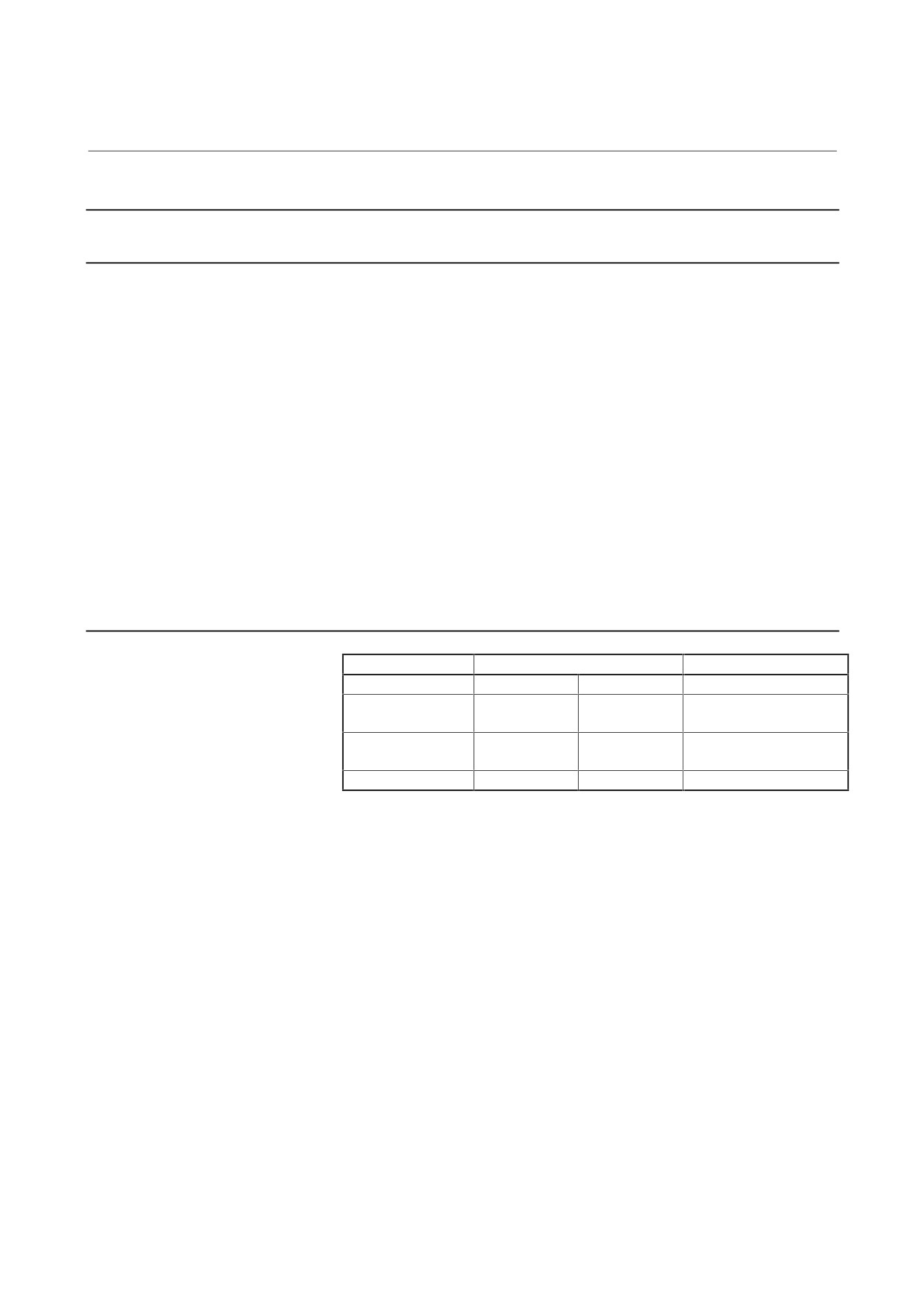
(2) A06B-6072-H051
(A20B-1005-0740) check terminal output
signals
Check terminal
Signal name
Check terminal
Signal name
LM
Load meter signal
PA1
Phase A sine wave signal 1
SM
Speed meter signal
PB1
Phase B sine wave signal 1
IU
Phase U current(*1)
PS1
Phase Z sine wave signal 1
IV
Phase V current(*1)
PA2
Phase A sine wave signal 2
VDC
DC link voltage
PB2
Phase B sine wave signal 2
VRM
Sensor reference voltage
PS2
Phase Z sine wave signal 2
MSA1
Magnetic sensor output MSA signal
PA3
Phase A sine wave signal 3
(main)
LSA1
Magnetic sensor output LSA signal
PB3
Phase B sine wave signal 3
(main)
EXTSC1
External one-rotation signal (main)
PA4
Phase A sine wave signal 4
MSA2
Magnetic sensor output MSA signal
PB4
Phase B sine wave signal 4
(sub)
LSA2
Magnetic sensor output LSA signal (sub)
OVR2
Analog override command
EXTSC2
External one-rotation signal (sub)
24V
+24 VDC power check
PAD
Phase A of position coder signal output
15V
+15 VDC power check
PBD
Phase B of position coder signal output
5V
5 VDC power check
PSD
Phase Z of position coder signal output
GND
0 V
Check terminal arrangement
PIL
LM
IU
Display
LSA2
LSA1
SM
IV
MSA2
MSA1
VRM
VDC
EXTSC2
EXTSC1
0V
0V
PBA
PA3
PA2
Operation
PA1
PBB
buttons
PB3
*1
The value measured on the IU pin
PB2
PB1
corresponds to the actual current as follows:
PSB
MODE
UP
5V
PS2
PS1
Model
Conversion value (A/V)
PA4
DATA
15V
SET
DOWN
SPM-15
50
0V
0V
PB4
24V
SPM-22
66.7
OVR2
SPM-26
100
SPM-30
133
- 70 -
4. CONFIRMATION OF
B-65165E/02
START-UP PROCEDURE
THE OPERATION
4.3.6
Observing Data Using the Spindle Check Board
4.3.6.1
Overview
By using the check board, you can convert digital signals used for
control in the spindle amplifier module to analog voltage, and observe
the conversion result with an oscilloscope. The internal data can be
indicated also with the five-digit display.
• A20B-2001-0830
This model has two analog output channels (CH1 and CH2) at
which the internal data (with output of -5 V to +5 V) can be
observed. It also has CH1D and CH2D at which specific bits such
as data bits can be observed.
• A20B-1005-0740
This model outputs internal data (output of 0 to 11 V) at terminals
LM and SM using the analog output circuit for the load meter (LM)
and speedometer (SM).
4.3.6.2
Major characteristics
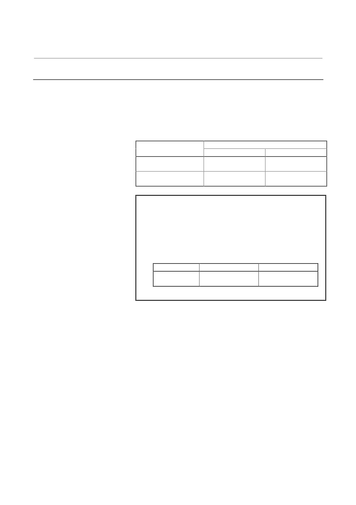
Item
A20B-2001-0830
A20B-1005-0740
Measurement point
CH1, CH2
CH1D, CH2D
LM, SM
Output voltage
-5 to +5 V
H: 2 Vmin
0 to 11 V
range
L:
0.8 Vmax
Resolution
About 39 mV
-
About 43 mV(11 V/256)
(10 V/256)
Output impedance
10 kΩmax
10 kΩmax
10 kΩmax
- 71 -
4. CONFIRMATION OF
THE OPERATION
START-UP PROCEDURE
B-65165E/02
4.3.6.3
Observation method
By setting data using four DIP switches on the check board, you can
output internal data to the five-digit display, analog voltage output
circuit, channels 1 and 2 (LM and SM or CH1 and CH2).
Data on channels 1 and 2 is the one from an 8-bit D/A convertor.
The correspondence between channel 1/2 and the check terminal is
listed below.
Check terminal
Measurement point
A20B-2001-0830
A20B-1005-0740
Channel 1
CH1
LM
CH1D, data bit 0
Channel 2
CH2
SM
CH2D, data bit 0
NOTE
When using printed-circuit board A20B-1005-0740,
set DIP switches S2 and S3 on the spindle amplifier
module front panel to OFF. After observation, set
them to ON.
This operation is not necessary when you use
printed-circuit board A20B-2001-0830.
DIP switch
ON position
OFF position
S2, S3
Output voltage is
Output voltage is not
filtered out.
filtered out.
- 72 -

4. CONFIRMATION OF
B-65165E/02
START-UP PROCEDURE
THE OPERATION
4.3.6.4
Specifying data to be monitored
<1> Press the four setting switches at the same time for at least a
second ."FFFFF" will be displayed on the indicator.
<2> Turn off the switches and press the "MODE" switch. "d-00" will
be displayed on the indicator and the system will enter the mode
for monitoring internal data.
In this mode, the motor can be operated normally.
<3> Press the "UP" or "DOWN" switch while holding down the
"MODE" switch. The indicator display will change in the range
of "d-00" to "d-12".
<4> The following shows the correspondence between the
destinations of the internal data of the serial spindle and addresses
d-01 to d-12.
d-01 to d-04: Specifies the amount of data to be output to the
indicator, data shift, and output format (decimal
or hexadecimal).
d-05 to d-08: Specifies the amount of data to be output to the
LM terminal, data shift, and whether an offset is
provided.
d-09 to d-12: Specifies the amount of data to be output to the
SM terminal, data shift, and whether an offset is
provided.
<5> Select address d-xx in the procedure for setting data described in
<3>.
<6> Turn off the "MODE" switch. "d-xx" will disappear 0.5 second
later, and the data will be displayed for a second.
Change the set data using the "UP" or "DOWN" switch within the
second the data is displayed.
<7> When more than a second elapses without pressing the "UP" or
"DOWN" switch, data cannot be changed.
If the "MODE" switch is turned on or off, however, setting can be
started from the beginning of the step in item <6>.
- 73 -
4. CONFIRMATION OF
THE OPERATION
START-UP PROCEDURE
B-65165E/02
4.3.6.5
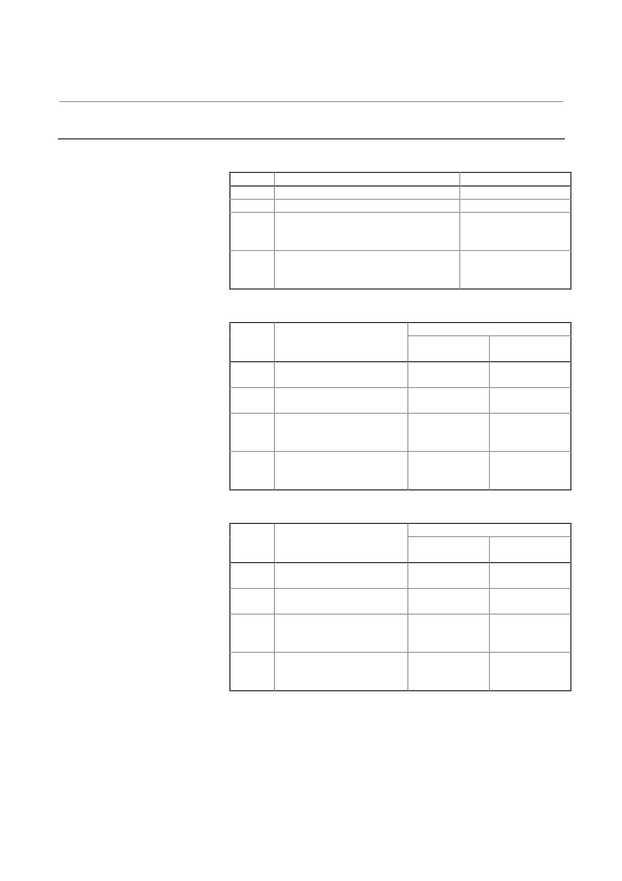
Address descriptions and initial values (SPM)
[Output to the indicator]
Address
Description
Initial value
d-01
Specifies a data number.
0
d-02
Shift at data output (0 to 31 bits)
0
d-03
Data shift direction
0
0 : Data is shifted right.
1 : Data is shifted left.
d-04
Display format
0
0 : Decimal notation
1 : Hexadecimal notation(0 to F)
[Output to the channel 1]
Initial value
Address
Description
A20B-2001-0830
A20B-1005-0740
(CH1)
(LM)
d-05
Specifies a data number
218
132
(U-phase current)
d-06
Shift at data output
8
0
(0 to 31 bits)
d-07
Data shift direction
0
0
0: Data is shifted right
1: Data is shifted left
d-08
Offset
1
0
0: Not provided
1: Provided
[Output to the channel 2]
Initial value
Address
Description
A20B-2001-0830
A20B-1005-0740
(CH1)
(SM)
d-09
Specifies a data number
19
131
(Motor velocity)
d-10
Shift at data output
18
0
(0 to 31 bits)
d-11
Data shift direction
0
0
0: Data is shifted right
1: Data is shifted left
d-12
Offset
1
0
0: Not provided
1: Provided
- 74 -
4. CONFIRMATION OF
B-65165E/02
START-UP PROCEDURE
THE OPERATION
4.3.6.6
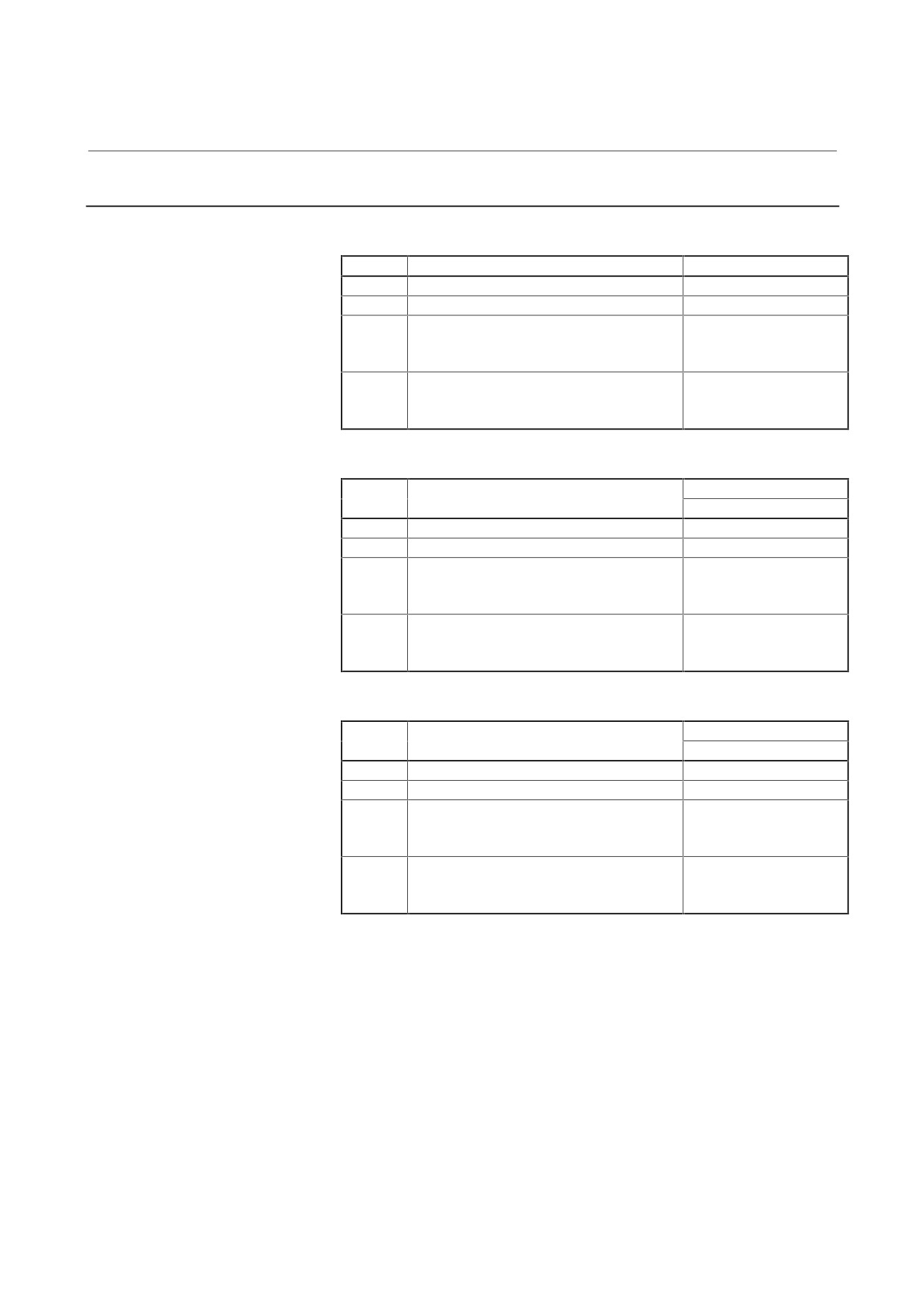
Address descriptions and initial values (SPMC)
[Output to the indicator]
Address
Description
Initial value
d-01
Specifies a data number.
0
d-02
Shift at data output (0 to 31 bits)
0
d-03
Data shift direction
0
0 : Data is shifted right.
1 : Data is shifted left.
d-04
Display format
0
0 : Decimal notation
1 : Hexadecimal notation(0 to F)
[Output to the channel 1]
Initial value
Address
Description
A20B-2001-0830 (CH1)
d-05
Specifies a data number
54 (Spindle load level)
d-06
Shift at data output (0 to 31 bits)
6
d-07
Data shift direction
0
0: Data is shifted right
1: Data is shifted left
d-08
Offset
0
0: Not provided
1: Provided
[Output to the channel 2]
Initial value
Address
Description
A20B-2001-0830 (CH1)
d-09
Specifies a data number
34 (U-phase current)
d-10
Shift at data output (0 to 31 bits)
8
d-11
Data shift direction
0
0: Data is shifted right
1: Data is shifted left
d-12
Offset
1
0: Not provided
1: Provided
- 75 -
4. CONFIRMATION OF
THE OPERATION
START-UP PROCEDURE
B-65165E/02
4.3.6.7
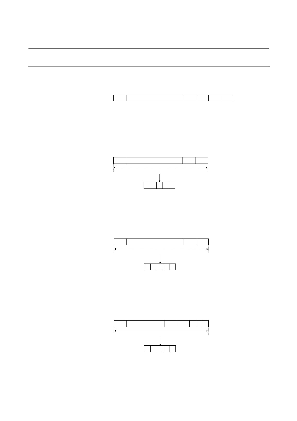
Principles in outputting the internal data of the serial spindle
The length of data is 32 bits (BIT31 TO BIT00) unless it is described as
16 bits.
BIT31
……
BIT03
BIT02
BIT01
BIT00
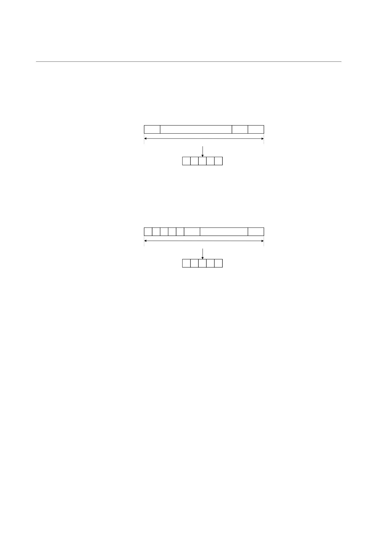
<1> Example of output to the indicator
Example1
Displaying data in decimal
When the number of digits to shift data (d-02)=0 and display format
(d-04)=0 (decimal notation): The last 16 bits of data (BIT15 to BIT00)
are converted into decimal (0 to 65535 max.) and displayed.
BIT15
……
BIT01
BIT00
16 bits
Converted into decimal
data and displayed
Indicator
X
X
X
X
X
Example2
Displaying data in hexadecimal
When the number of digits to shift data (d-02)=0 and display format
(d-04)=1 (hexadecimal notation): The last 16 bits of data (BIT15 to
BIT00) are converted into hexadecimal
(0 to FFFFF max.) and
displayed.
BIT15
……
BIT01
BIT00
16 bits
Converted into hexadecimal
data and displayed
Indicator
X
X
X
X
(The fifth digit is blank.)
Example3
Shifting data left
When the number of digits to shift data (d-02)=3, the shift direction is
left
(d-03=1), and display format (d-04)=1 (hexadecimal notation):
Data in BIT12 to BIT00 and the last three bits of data (=0) are
converted into hexadecimal (0 to FFFFF max.) and displayed.
BIT12
……
BIT01
BIT00
0
0
0
16 bits
Converted into hexadecimal
data and displayed
Indicator
X
X
X
X
(The fifth digit is blank.)
- 76 -
4. CONFIRMATION OF
B-65165E/02
START-UP PROCEDURE
THE OPERATION
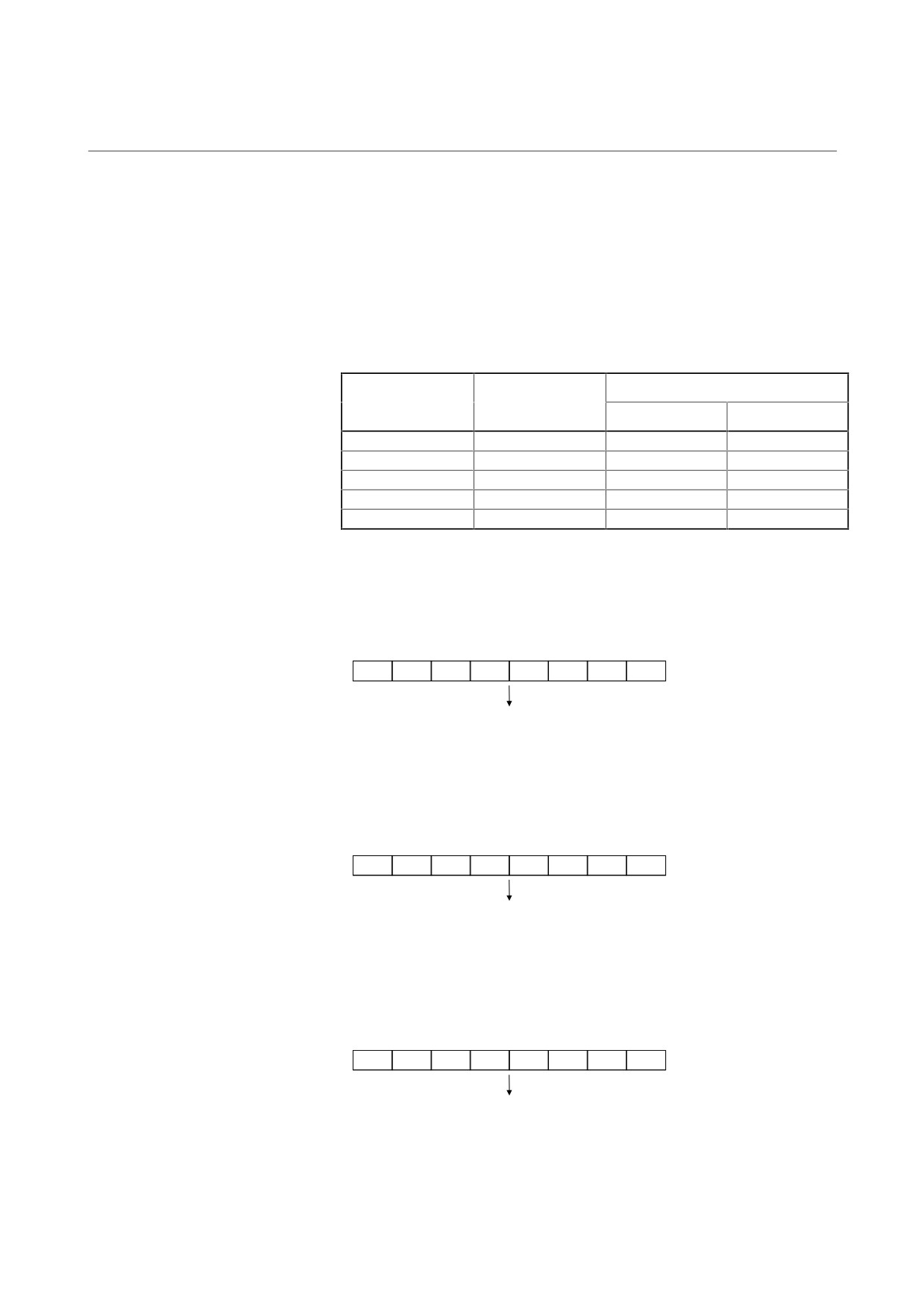
Example4
Shifting data right
When the number of digits to shift data (d-02)=5, shift direction is right
(d-03=0), and display format (d-04)=0 (decimal notation): Data in
BIT20 to BIT05 is converted into decimal (0 to 65535 max.) and
displayed.
BIT20
……
BIT06
BIT05
16 bits
Converted into decimal
data and displayed
Indicator
X
X
X
X
X
Example5
Shifting data right when the data length is 16 bits
When the data length is 16 bits, data shift (d-02)=5, shift direction is
right (d-03=0), and display format is decimal notation (d-04=0): The
first five bits of data and data in BIT15 to BIT05 are converted into
decimal and displayed.
0
0
0
0
0
BIT15
……
BIT05
16 bits
Converted into decimal
data and displayed
Indicator
X
X
X
X
X
- 77 -
4. CONFIRMATION OF
THE OPERATION
START-UP PROCEDURE
B-65165E/02
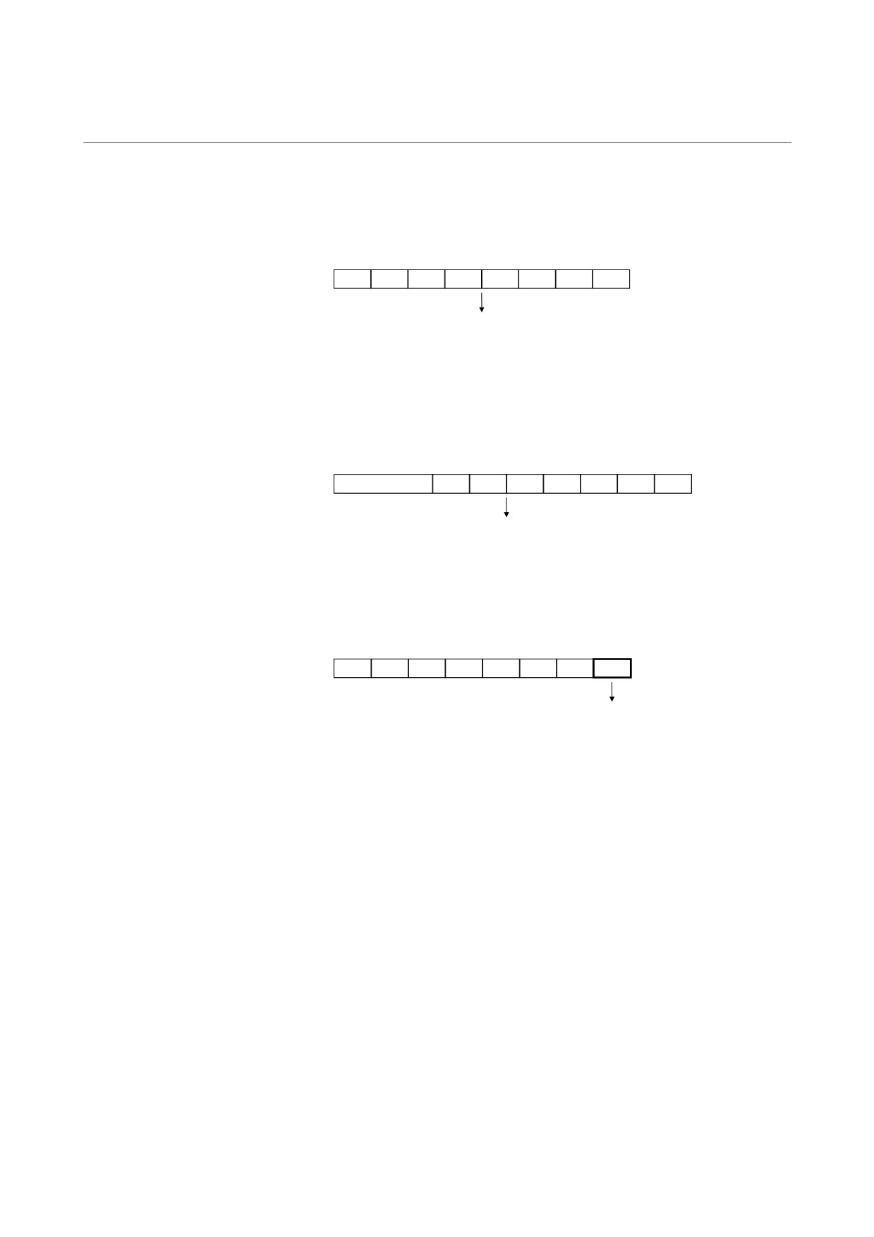
<2> Example of output to the channel 1
Internal data is output to channel 1 by setting it in an 8-bit D/A
convertor.
The output range of the D/A convertor varies from one printed-
circuit board to another. The output ranges from -5 V to +5 V
(printed-circuit board A20B-2001-0830) or from 0 V to +11 V
(printed-circuit board A20B-1005-0740) according to the internal
data that is set. See the table below.
Setting d-08
Output on channel 1
Internal data in
(whether there is
binary (decimal)
A20B-2001-0830
A20B-1005-0740
offset)
00000000(
0)
0
-5V
0V
11111111( 255)
0
+4.96V
+11V
10000000(-128)
1
-5V
0V
00000000(
0)
1
0V
+5.5V
01111111( 127)
1
+4.96V
+11V
Example1
Data set
When the number of digits to shift data (d-06)=0 and when no offset is
provided (d-08=0): The last eight bits of data (BIT07 to BIT00) is set
in the D/A converter of the LM terminal.
BIT07
BIT06
BIT05
BIT04
BIT03
BIT02
BIT01
BIT00
Set in the D/A converter for channel 1 output
Example2
Shifting data left
When the number of digits to shift data (d-06)=3, shift direction is right
(d-07=1), and no offset is provided (d-08=0): Data in BIT14 to BIT00
and the last three bits of data (=0) are set in the D/A converter.
BIT04
BIT03
BIT02
BIT01
BIT00
0
0
0
Set in the D/A converter for channel 1 output
Example3
Shifting data right
When the number of digits to shift data (d-06)=10, shift direction is
right (d-07=1), and no offset is provided (d-08=0): Data in BIT17 to
BIT10 is set in the D/A converter.
BIT17
BIT16
BIT15
BIT14
BIT13
BIT12
BIT11
BIT10
Set in the D/A converter for channel 1 output
- 78 -
4. CONFIRMATION OF
B-65165E/02
START-UP PROCEDURE
THE OPERATION
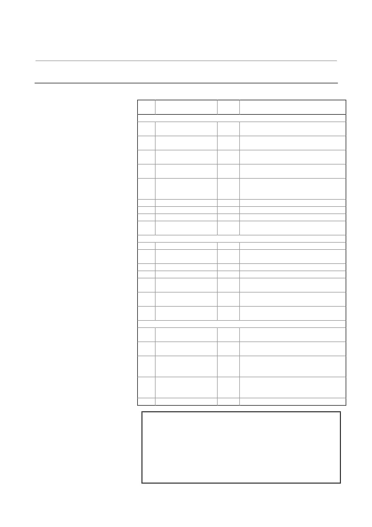
Example4
Shifting data right when the data length is 16 bits
When the data length is 16 bits, data shift (d-06)=10, shift direction is
right (d-07=0), and no offset is provided (d-08=0): The first two bits of
data (=0) and data in BIT15 to BIT10 are set in the D/A converter.
0
0
BIT15
BIT14
BIT13
BIT12
BIT11
BIT10
Set in the D/A converter for channel 1 output
Example5
If an offset is provided
When the number of digits to shift data (d-06)=10, shift direction is
right
(d-07=0), and an offset is provided (d-08=1): Data in most
significant bit BIT17 (to which 1 is added) and data in BIT16 to BIT10
are set in the D/A converter.
BIT17 Data +1
BIT16
BIT15
BIT14
BIT13
BIT12
BIT11
BIT10
Set in the D/A converter for channel 1 output
Example6
Data bit observation
(for printed-circuit board A20B-2001-0830 only)
For data shift (d-06) = 0 with no offset (d-08 = 0), the lowest data bit
(BIT00) can be observed as a high/low level at check terminal CH1D.
BIT07
BIT06
BIT05
BIT04
BIT03
BIT02
BIT01
BIT00
Output to check terminal CH1D
<3> Example of output to the channel 2
Output to the channel 2 is the same as that to the channel 1.
However, the addresses for setting data
(d-09 to d-12) are
different from those for output to the channel 1.
Setting velocity information in the channel 1 and the number of
errors in the channel 2 enables simultaneous monitoring of the
change in each data item using the two channels.
- 79 -
4. CONFIRMATION OF
THE OPERATION
START-UP PROCEDURE
B-65165E/02
4.3.6.8
Data numbers
(1) SPM
Data
Data
Description
Remarks
No.
length
Main data
16
Motor speed command
32
The 12th bit (BIT12) indicates a units in
rpm.
19
Motor speed
32
The 12th bit (BIT12) indicates a units in
rpm.
25
Motor speed deviation
32
(Speed command - motor speed) The
12th bit (BIT12) indicates a units in rpm.
4
Move command
32
Number of command pulses for ITP
(usually 8 ms)
9
Positioning error
32
Number of erroneous pulses (Spindle
synchronous control Cs contour control
Rigid mode)
90
Torque command
16
0 to ±16384
131
Speedometer data
16
SM terminal
132
Load meter data
16
LM terminal
136
Position error
32
Number of erroneous pulses (Position
coder orientation)
Data between the spindle and CNC
5
Speed command data
16
±16384 for the maximum speed command
6
Spindle control signal 1
16
See the command signal from the PMC to
spindle in (4).
10
Load meter data
16
±16384 for maximum output
11
Motor speed data
16
±16384 for maximum speed
12
Spindle status signal 1
16
See the status signal from the spindle to
PMC in (4).
66
Spindle control signal 2
16
See the command signal from the PMC to
spindle in (4).
182
Spindle status signal 2
16
See the status signal from the spindle to
PMC in (4).
Other data
218
Phase U current (A/D
16
10 V/FS by shifting 8 bits left(Note)
conversion data)
219
Phase V current (A/D
16
conversion data)
121
Magnetic sensor signal
16
15.4 V/FS by shifting 8 bits left(Note)
(MS signal on the main
side)
125
Magnetic sensor signal
16
(MS signal on the sub
side)
162
DC link voltage
16
1000 V/FS by shifting 8 bits left(Note)
NOTE
Printed-circuit board A20B-2001-0830 has no check
pin for IU, IV, VDC, MSA1 or MSA2. To observe
signals such as phase U current, output the
corresponding internal data to channels 1 and 2.
Shift the data to be observed by 8 bits left with an
offset. The table (3) lists the internal data
conversion.
- 80 -
4. CONFIRMATION OF
B-65165E/02
START-UP PROCEDURE
THE OPERATION
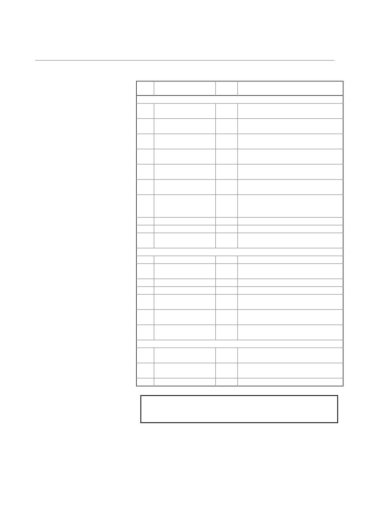
(2) SPMC
Data
Data
Description
Remarks
No.
length
Main data
19
Motor speed command
32
The 12th bit (bit 12) indicates the unit of
min-1.
8
Motor speed
32
The 12th bit (bit 12) indicates the unit of
min-1 (only when a position coder is used)
13
Estimated motor speed
32
The 12th bit (bit 12) indicates the unit of
min-1.
18
Spindle speed
32
The 12th bit (bit 12) indicates the unit of
min-1 (only when a position coder is used)
7
Motor speed deviation
32
(Speed command - motor speed). The
12th bit (bit 12) indicates the unit of min-1.
4
Move command
32
Number of command pulses for ITP
(usually 8 ms)
9
Position error
32
Number of erroneous pulses (spindle
synchronization, Cs contour control, rigid
mode)
90
Torque command
16
0 to ±16384
131
Load meter data
16
LM pin
117
Position error
32
Number of erroneous pulses (position
coder orientation)
Data between the spindle and CNC
74
Speed command data
16
±16384 for the maximum speed command
77
Spindle control signal 1
16
See the command signal from the PMC to
spindle in (4).
54
Load meter data
16
±16384 for maximum output
55
Motor speed data
16
±16384 for maximum speed
61
Spindle status signal 1
16
See the status signal from the spindle to
PMC in (4).
78
Spindle control signal 2
16
See the command signal from the PMC to
spindle in (4).
62
Spindle status signal 2
16
See the status signal from the spindle to
PMC in (4).
Other data
34
Phase U current (A/D
16
10 V/FS by shifting 8 bits left(Note)
conversion data)
35
Phase V current (A/D
16
conversion data)
39
DC link voltage
16
1000 V/FS by shifting 8 bits left(Note)
NOTE
Internal data conversion is performed as shown in
the Table in (3).
- 81 -
4. CONFIRMATION OF
THE OPERATION
START-UP PROCEDURE
B-65165E/02
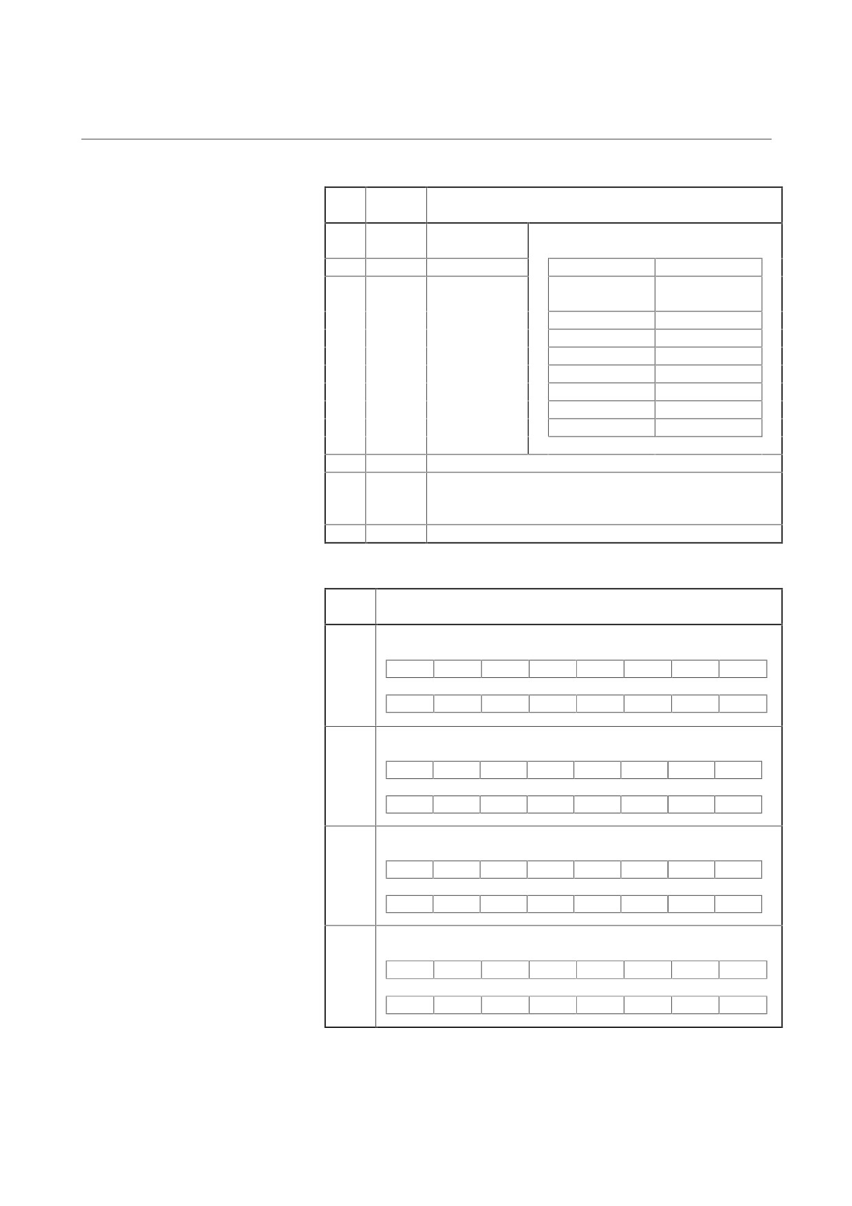
(3) Internal data conversion (A20B-2001-0830)
Data
Signal
Description (All are voltage values on check pins when
No.
name
the shift amount is 8.)
218
IU
Phase U current
The current is positive when it is input to the
amplifier.
219
IV
Phase V current
Model
Conversion result
SPM-2.2, 5.5
16.7 A/1 V
SPM-11HV
SPM-11, 15HV
33.3 A/1 V
SPM-15, 25HV
50.0 A/1 V
SPM-22, 45HV
66.7 A/1 V
SPM-26
100 A/1 V
SPM-30, 75HV
133 A/1 V
SPM-45
200 A/1 V
SPM-55
233 A/1 V
162
VDC
DC link voltage signal 100 V/1 V (200 V/1 V for SPM-HV)
121
MSA1
Magnetic sensor output MSA signal 1 1.54 V/1 V
(Adjustment value on check board: Single amplitude 2.0 V
min, offset ±300 mV max)
125
MSA2
Magnetic sensor output MSA signal 2 1.54 V/1 V
(4) Spindle control signals (PMC signals)
Data
Description
No.
6
Spindle control signal 1 (command signal from the PMC to spindle)
BIT15
BIT14
BIT13
BIT12
BIT11
BIT10
BIT09
BIT08
RCH
RSL
INTG
SOCN
MCFN
SPSL
*ESP
ARST
BIT07
BIT06
BIT05
BIT04
BIT03
BIT02
BIT01
BIT00
MRDY
ORCM
SFR
SRV
CTH1
CTH2
TLMH
TLML
66
Spindle control signal 2 (control signal from the PMC to spindle)
BIT15
BIT14
BIT13
BIT12
BIT11
BIT10
BIT09
BIT08
*DOPN
DSCN
SORSL
MPOF
SLV
MORCM
BIT07
BIT06
BIT05
BIT04
BIT03
BIT02
BIT01
BIT00
RCHHG
MFNHG
INCMD
OVR
DEFMD
NRRO
ROTA
INDX
Spindle status signal 1 (status signal from the spindle to PMC)
12
BIT15
BIT14
BIT13
BIT12
BIT11
BIT10
BIT09
BIT08
MOAR2
MOAR1
POAR2
SLVS
RCFN
RCHP
CFIN
CHP
BIT07
BIT06
BIT05
BIT04
BIT03
BIT02
BIT01
BIT00
ORAR
TLM
LDT2
LDT1
SAR
SDT
SST
ALM
182
Spindle status signal 2 (status signal from the spindle to PMC)
BIT15
BIT14
BIT13
BIT12
BIT11
BIT10
BIT09
BIT08
BIT07
BIT06
BIT05
BIT04
BIT03
BIT02
BIT01
BIT00
EXOF
SOREN
MSOVR
INCST
PC1DT
- 82 -
4. CONFIRMATION OF
B-65165E/02
START-UP PROCEDURE
THE OPERATION
4.3.6.9
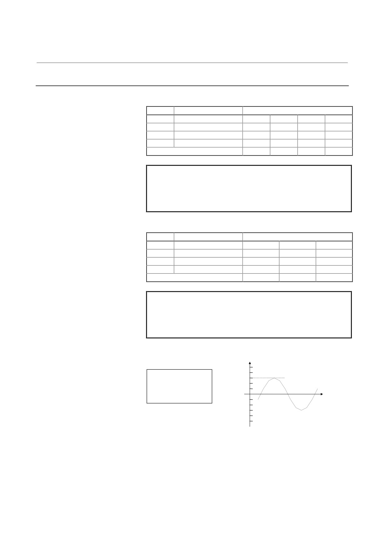
Example of monitoring data
<1> Example of monitoring a positioning error using the channel 1
Address
Description
Set Data
d-05
Data number
9
9
9
9
d-06
Data shift
0
1
1
2
d-07
Data shift direction
0
0
1
1
d-08
Offset
1
1
1
1
Data unit (NOTE)
256p/FS
512p/FS
128p/FS
64p/FS
NOTE
Printed-circuit board A20B-2001-0830:
FS=10V (-5V to 5V)
Printed-circuit board A20B-1005-0740:
FS=11V (0V to 11V)
<2> Example of monitoring a motor speed using the channel 2
Address
Description
Set Data
d-09
Data number
19
19
19
d-10
Data shift
12
13
11
d-11
Data shift direction
0
0
0
d-12
Offset
0
0
0
Data unit (NOTE)
256min-1/FS
512min-1/FS
128p/FS
NOTE
Printed-circuit board A20B-2001-0830:
FS=10V (-5V to 5V)
Printed-circuit board A20B-1005-0740:
FS=11V (0V to 11V)
<3> Observation of phase U current in the SPM-11
Setting of observation data
+5 V
Data No.
218
100 A
Shift amount
8
Shift direction
0 (shifted left)
Offset
1 (provided)
0 V
33.3 A/1 V
-5 V
- 83 -

5. PERIODIC MAINTENANCE
OF SERVO AMPLIFIER
START-UP PROCEDURE
B-65165E/02
5
PERIODIC MAINTENANCE OF SERVO
AMPLIFIER
- 84 -
5. PERIODIC MAINTENANCE
B-65165E/02
START-UP PROCEDURE
OF SERVO AMPLIFIER
5.1
BATTERY FOR THE ABSOLUTE PULSE CODER
When the interface with the CNC is type B or FSSB, the battery for the
absolute pulse coder is required for absolute-position detection.
The battery for the absolute pulse coder is installed in the following
two methods:
Method 1: Installing a special lithium battery in the SVM
• Use A06B-6073-K001.
Method 2: Using a battery case (A06B-6050-K060)
• Use A06B-6050-K061 or a commercially available
size-D battery.
• A connection cable (A06B-6093-K810) is required.
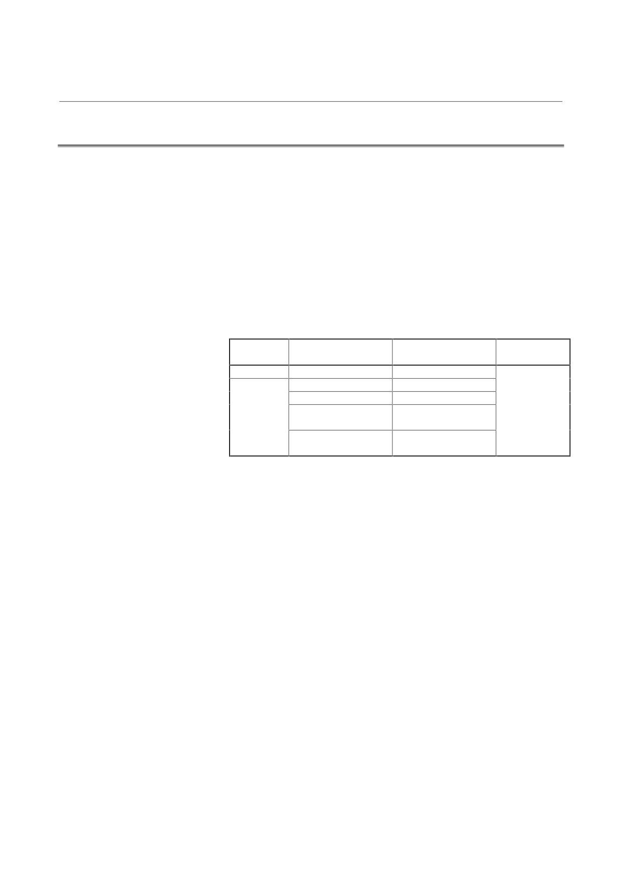
Order specification
Use
Name
Classification
drawing No.
Method 1
Battery
A06B-6073-K001
Option
Method 2
Battery
A06B-6050-K061
Battery case
A06B-6050-K060
Cable for battery
A06B-6093-K810
connection
Connector for battery
A06B-6093-K303
connection
- 85 -
5. PERIODIC MAINTENANCE
OF SERVO AMPLIFIER
START-UP PROCEDURE
B-65165E/02
5.1.1
Installing a Special Lithium Battery in the SVM (Method 1)
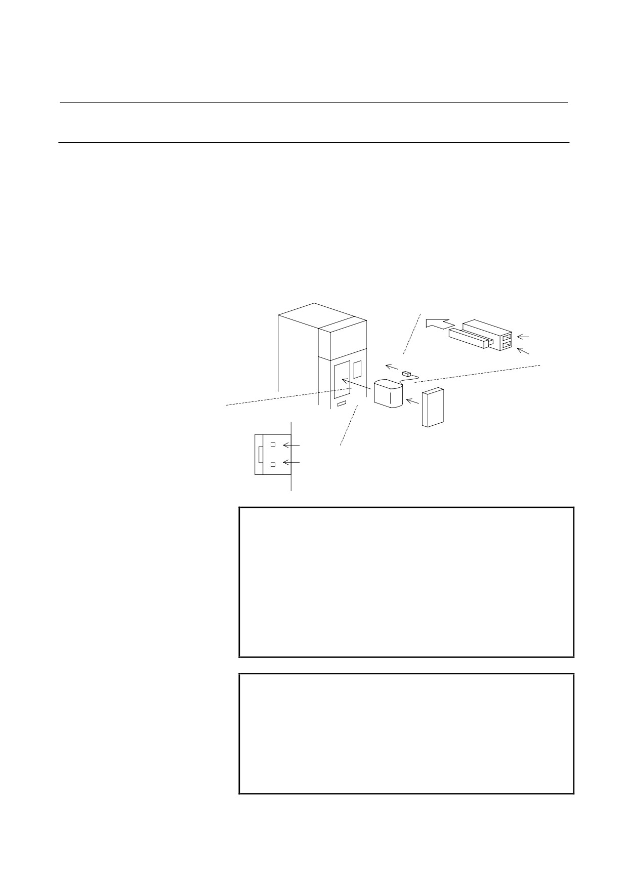
A special lithium battery (A06B-6073-K001) can be installed in the
SVM (see the figure below).
[Installation procedure]
(1) Remove the battery cover from the SVM.
(2) Install the battery in the SVM as shown in the figure below.
(3) Install the battery cover.
(4) Attach the battery connector to CX5X or CX5Y of the SVM.
SVM
Inserting direction
Cable side
Red: +6 V
Connector
Black: 0 V
Battery
CX5X, CX5Y
Battery cover
+6 V
0 V
WARNING
1
Install the battery with correct polarity. If the battery
is installed with incorrect polarity, it may overheat,
blow out, or catch fire.
2
When installing the battery with its connector
attached to connector CX5X or CX5Y, attach the
factory-installed protection socket to the unused
connector. When the +6-V and 0-V pins of CX5X or
CX5Y are short-circuited, the battery may overheat,
blow out, or catch fire.
CAUTION
1
You may attach the battery connector to either CX5X
or CX5Y.
2
When the battery is installed in the SVM from the
side from which the cable is drawn, the cable may be
stretched tight, which can lead to a poor contact
condition. Therefore, install the battery so that the
cable is not extended tightly.
- 86 -

5. PERIODIC MAINTENANCE
B-65165E/02
START-UP PROCEDURE
OF SERVO AMPLIFIER
5.1.2
Using a Battery Case (A06B-6050-K060) (Method 2)
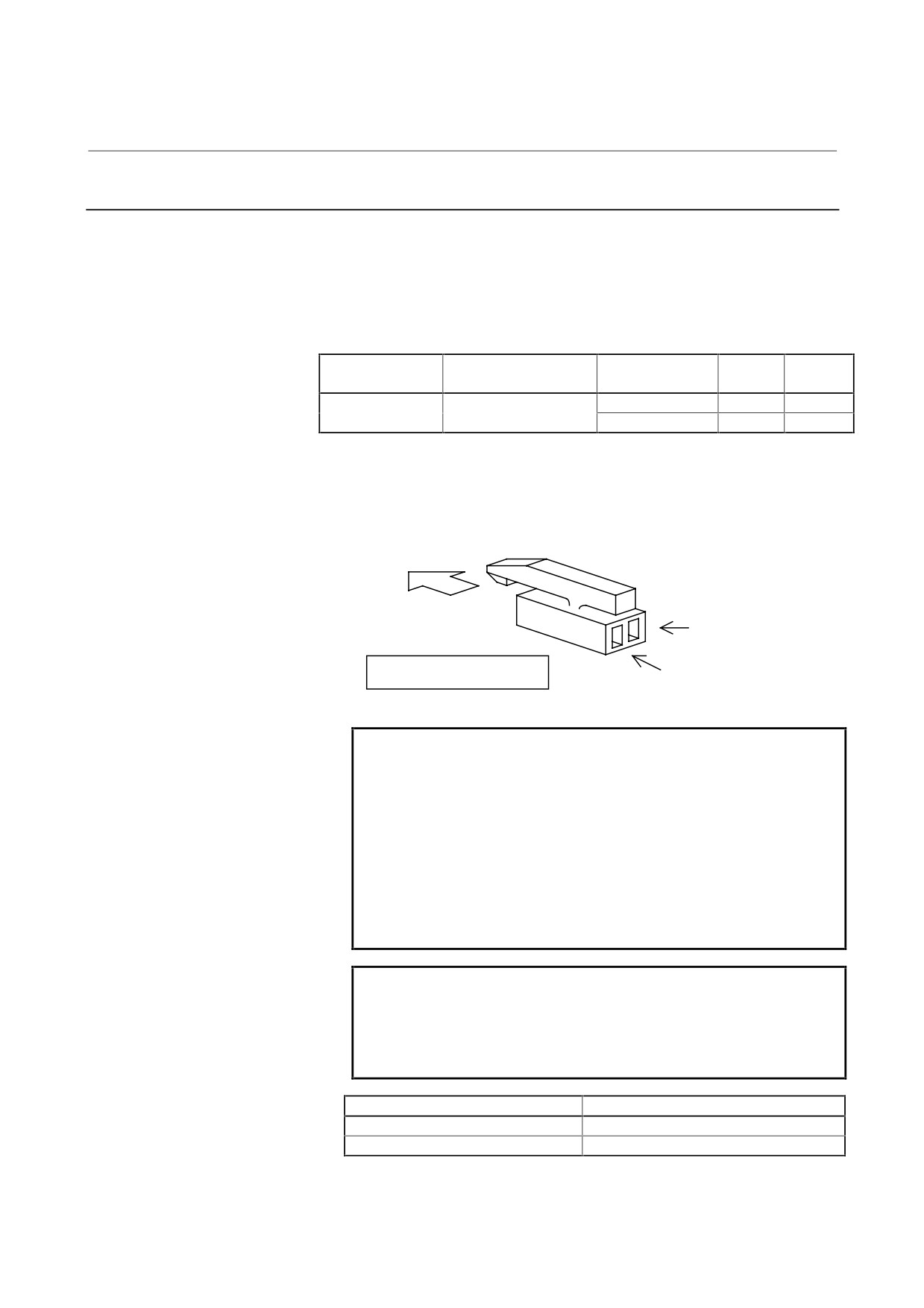
Details of connection of the battery unit to the SVM
Battery unit
SVM
+6 V
CX5X, CX5Y (2)
0 V
CX5X, CX5Y (1)
0.3 mm2 × 2
Screw terminal: M3
Housing
:
1L-L2S-S3L-B(N)
Crimp terminal: 1.25-4
Contact
:
1L-C2-1-00001
Manufacturer: Japan Aviation Electronics
Industry, Ltd.
Note) A special crimping tool is required to attach the contacts to a
cable. Contact the following:
Japan Aviation Electronics Industry, Ltd.
WARNING
1
Install the battery with correct polarity. If the battery
is installed with incorrect polarity, it may overheat,
blow out, or catch fire.
2
When installing the battery with its connector
attached to connector CX5X or CX5Y, attach the
factory-installed protection socket to the unused
connector. When the +6-V and 0-V pins of CX5X or
CX5Y are short-circuited, the battery may overheat,
blow out, or catch fire.
CAUTION
1
You may attach the battery connector to either CX5X
or CX5Y.
2
To an unused connector, attach the supplied
protection socket.
- 87 -
5. PERIODIC MAINTENANCE
OF SERVO AMPLIFIER
START-UP PROCEDURE
B-65165E/02
5.1.3
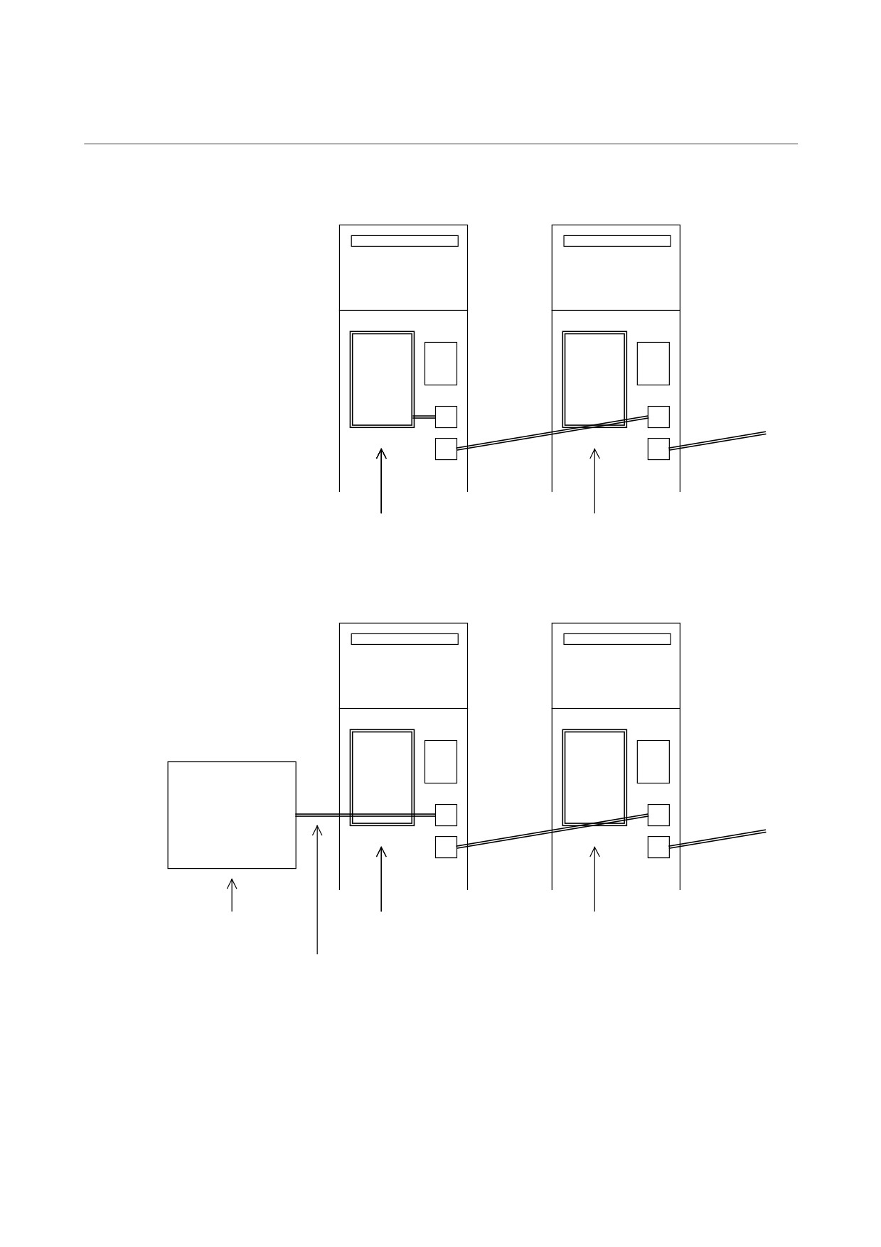
Connecting a Battery to Multiple SVMs
There are two methods for connecting a battery to more than one SVM.
(1) Connecting a battery installed in one SVM to other SVMs
(2) Connecting a separate battery unit to SVMs
The following connector kit is provided for preparing cables:
Part number of
Drawing No.
Manufacturer
Product
Quantity
manufacturer
A06B-6093-K303
Japan Aviation
1L-L2S-S3L-B(N)
Housing
2
Electronics Industry, Ltd.
1L-C2-1-00001
Contact
4
Note) A special crimping tool is required to attach contacts to a cable.
Contact the following:
Japan Aviation Electronics Industry, Ltd.
Inserting direction
+6 V
1L-L2S-S3L-B(N)
Cable side
0 V
WARNING
1
Install the battery with correct polarity. If the battery
is installed with incorrect polarity, it may overheat,
blow out, or catch fire.
2
When installing the battery with its connector
attached to connector CX5X or CX5Y, attach the
factory-installed protection socket to the unused
connector. When the +6-V and 0-V pins of CX5X or
CX5Y are short-circuited, the battery may overheat,
blow out, or catch fire.
CAUTION
Note that when a battery is shared among more than
one servo amplifier module (SVM), the battery life
will shorten. The following table shows general life
times of batteries.
Battery type
General life time
Lithium battery
One year for three axes
Alkaline size D battery
One year for six axes
- 88 -
5. PERIODIC MAINTENANCE
B-65165E/02
START-UP PROCEDURE
OF SERVO AMPLIFIER
(1) Connecting a battery installed in one SVM to other SVMs
SVM
SVM
CX5X
CX5X
CX5Y
CX5Y
Battery contained
No battery
(2) Connecting a separate battery unit to SVMs
SVM
SVM
Battery unit
A06B-6050-K060
CX5X
CX5X
CX5Y
CX5Y
Battery contained
No battery
No battery
Cable between the battery and amplifier
A06B-6093-K810 (Only a 5-m cable is available.)
- 89 -

5. PERIODIC MAINTENANCE
OF SERVO AMPLIFIER
START-UP PROCEDURE
B-65165E/02
Details of connection between SVMs
SVM
SVM
CX5X, CX5Y (2)
CX5X, CX5Y (2)
CX5X, CX5Y (1)
CX5X, CX5Y (1)
0.3 mm2 × 2
Housing
:
1L-L2S-S3L-B(N)
Housing
:
1L-L2S-S3L-B(N)
Contact
:
1L-C2-1-00001
Contact
:
1L-C2-1-00001
Manufacturer: Japan Aviation
Manufacturer: Japan Aviation
Electronics Industry, Ltd.
Electronics Industry, Ltd.
- 90 -

5. PERIODIC MAINTENANCE
B-65165E/02
START-UP PROCEDURE
OF SERVO AMPLIFIER
5.1.4
Replacing the Battery
To prevent absolute-position information of the absolute pulse coder
from being lost, replace the battery while the power for control is on.
Follow the procedure explained below.
1.
Make sure that the power to the SVM is on (the 7-segment LED
on the front of the SVM is on).
2.
Make sure that the emergency stop button of the system has been
pressed.
3.
Make sure that the motor is not activated.
4.
Make sure that the DC link charge LED of the SVM is off.
5.
Remove the old battery, and install a new battery.
6.
This completes the replacement. You can turn off the power to
the system.
WARNING
1
When replacing the battery, be careful not to touch
bare metal parts in the panel. In particular, be
careful not to touch any high-voltage circuits due to
the electric shock hazard.
2
Before replacing the battery, check that the DC link
charge confirmation LED on the front of the servo
amplifier is off. Neglecting this check creates an
electric shock hazard.
3
Install the battery with correct polarity. If the battery
is installed with incorrect polarity, it may overheat,
blow out, or catch fire.
4
When installing the battery with its connector
attached to connector CX5X or CX5Y, attach the
factory-installed protection socket to the unused
connector. When the +6-V and 0-V pins of CX5X or
CX5Y are short-circuited, the battery may overheat,
blow out, or catch fire.
- 91 -
5. PERIODIC MAINTENANCE
OF SERVO AMPLIFIER
START-UP PROCEDURE
B-65165E/02
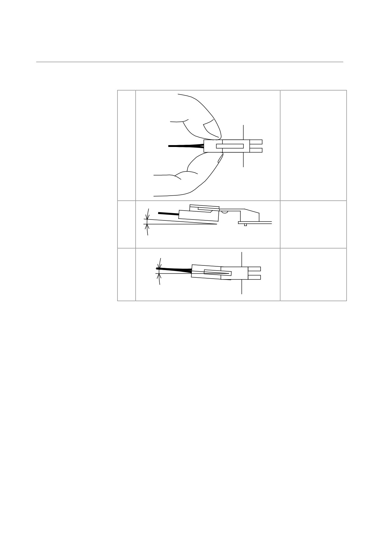
5.1.5
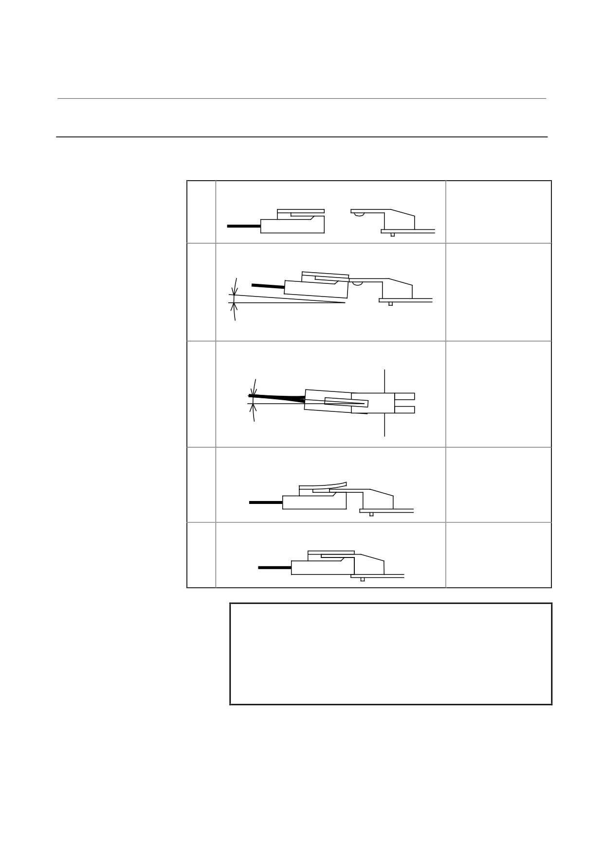
Attaching and Detaching Connectors
(1) Attaching connectors
<1>
Check the attachment
position.
<2>
Plug the cable
connector while raising
it slightly.
10 degrees or less
<5>
Here, the angle of the
cable connector to the
horizontal must be 5
degrees or less.
5 degrees or less
<3>
After passing the lock
pin, insert the
connector straight.
<4>
The attachment of the
connector is
completed.
CAUTION
When attaching or detaching the battery connector,
be careful not to apply excessive torsion to the
connector. When the connector is attached or
detached, applying excessive stress to the connector
can lead to a poor contact condition or other
problems.
- 92 -
5. PERIODIC MAINTENANCE
B-65165E/02
START-UP PROCEDURE
OF SERVO AMPLIFIER
(2) Detaching the connector
<1>
Hold both the sides of
the cable insulator and
the cable, and pull them
horizontally.
<2>
Pull out the cable side
while raising it slightly.
10 degrees or less
<3>
Here, the angle of the
cable to the horizontal
must be 5 degrees or
less.
5 degrees or less
- 93 -

II. TROUBLESHOOTING

B-65165E/02
TROUBLESHOOTING
1.OVERVIEW
1
OVERVIEW
This part describes the troubleshooting procedure for each module.
Read the section related to your current trouble to locate it and take an
appropriate action.
First, check the alarm number and STATUS display indicated on your
module with each list (alarm numbers in the list are those for the CNC)
in Chapter 2 to find the corresponding detailed information in Chapter
3.
Then take an appropriate action according to the detailed
information.
- 97 -