FANUC Alpha Series Motors and Modular Drives. Maintenance Manual (GFZ-65165E/02) - page 9
1. AC SERVO MOTOR
MAINTENANCE
TROUBLESHOOTING
B-65165E/02
(f) Replace the packing on the motor cover mounting surface.
Reusing old packing cannot provide sufficient sealing
performance. Whenever taking off the motor cover, be sure
to replace the packing.
(g) Connect the cable of the pulse coder.
(h) Install the motor cover. Be careful not to catch the lead wires
of the pulse coder. After installing the motor cover, fasten
the cover using the M4 hexagonal socket head bolts.
<2>-2 (Cable non-separation type)
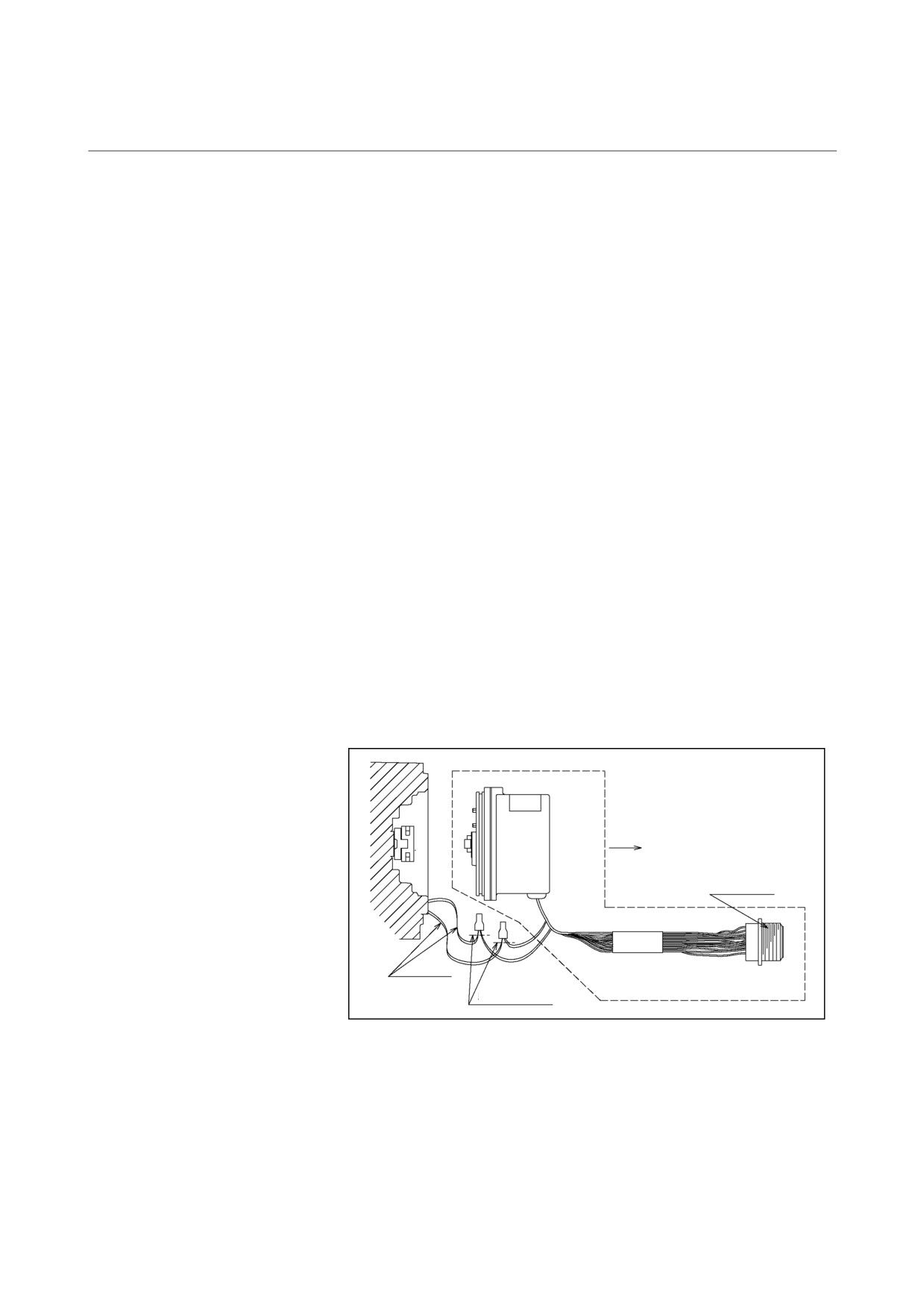
(a) Detach the cannon connector of the pulse coder from the red
motor cover.
(a)-1
Remove the M3 screw that retains the connector.
(a)-2
Shift the rubber packing, and remove the C-ring that
retains the insulator on the rear side (connection side)
of the connector to separate the connector housing
from the terminal section. Replace the rubber
packing with a new one.
(a)-3
Remove the connector terminal section from the
motor cover.
(a)-4
Set the housing in the removed pulse coder (the pulse
coder to be replaced with a new one) in place, and
hold the housing with the C-ring.
(b) Cut the lead wires of the thermal switch. The wires should
be cut at the root of the crimp terminals where possible.
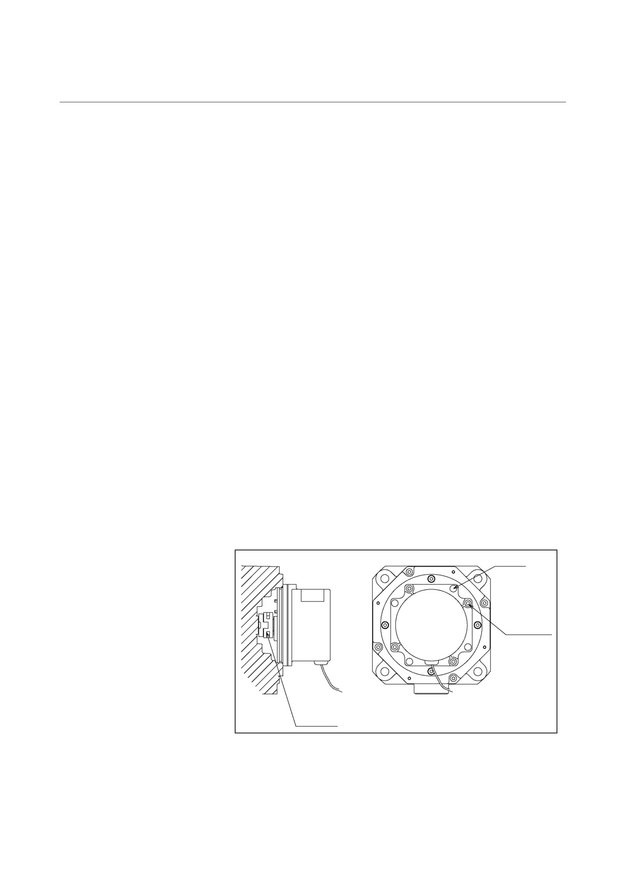
(c) Remove the four M4 hexagonal socket head bolts that retain
the pulse coder. Do not loosen the M3 bolts that retain the
pulse coder cover.
M4 × 10
Do not loosen
these bolts.
Oldham’s
coupling
(d) Remove the pulse coder and Oldham’s coupling.
- 220 -
1. AC SERVO MOTOR
B-65165E/02
MOTOR MAINTENANCE
MAINTENANCE
(e)
Set a new pulse coder and new Oldham’s coupling in the
motor. Although the mounting orientation is not specified in
particular, it is recommended that the pulse coder be set with
the same orientation as before the replacement. This is
because of the convenience of cabling. Place the Oldham’s
coupling with the correct orientation, and engage the teeth.
(f)
Fasten the pulse coder with the four M4 hexagonal socket
head bolts.
(g)
Replace the packing on the motor cover mounting surface.
Reusing old packing cannot provide sufficient sealing
performance. Whenever taking off the motor cover, be sure
to replace the packing.
(h)
Install the connector in the cover in the reverse order of step
(a). Keying is provided for the connector insulator (the
insulating material around the terminals). So, perform
keying (phase) alignment when installing the connector.
(i)
Connect the lead wires of the thermal switch. Peel off about
1 cm of the jacket from the cut end of each motor lead wire,
and tie the wire to the terminal of the pulse coder. Use of a
crimp terminal is recommended for connection.
(In case of
an emergency, insulate both connection portions with
insulating tape.)
(j)
Install the motor cover. Be careful not to catch the lead wires
of the pulse coder. After installing the motor cover, bolt the
cover.
Cannon connector
Thermal wire
Cut the wire at the root of
the crimp terminal.
- 221 -
1. AC SERVO MOTOR
MAINTENANCE
TROUBLESHOOTING
B-65165E/02
(3) Models α65 to α150
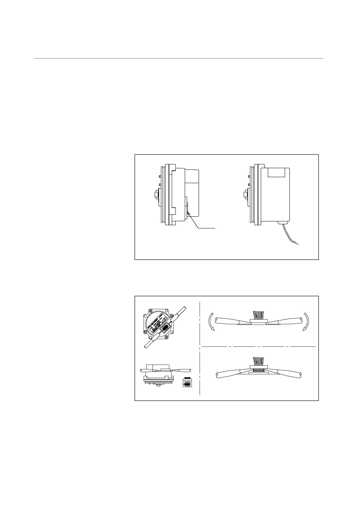
<1> Loosen the bolts that retain the red motor cover to remove
the cover. Check whether the pulse coder is of the cable
separation type (the pulse coder cable can be detached from
the red cover of the pulse coder) or of the cable non-
separation type
(the cable cannot be detached from the
cover). For the replacement of a cable separation type pulse
coder, see Item <2>-1. For the replacement of a cable non-
separation type pulse coder, see Item <2>-2.
Connector
Cable separation
Cable non-separation
type pulse coder
type pulse coder
<2>-1 (Cable separation type)
(a) Remove the cable of the pulse coder by using a screwdriver.
<1>
<2>
Cover
<3>
Cover
(b) Remove the four M4 hexagonal socket head bolts that retain
the pulse coder. Do not loosen the M3 bolts that retain the
pulse coder cover.
(c) Remove the pulse coder and Oldham’s coupling.
- 222 -
1. AC SERVO MOTOR
B-65165E/02
MOTOR MAINTENANCE
MAINTENANCE
(d) Set a new pulse coder and new Oldham’s coupling in the
motor. Although the mounting orientation is not specified in
particular, it is recommended that the pulse coder be set with
the same orientation as before the replacement. This is
because of the convenience of cabling. Place the Oldham’s
coupling with the correct orientation, and engage the teeth.
(e) Fasten the pulse coder with the four M4 hexagonal socket
head bolts.
(f) Replace the packing on the motor cover mounting surface.
Reusing old packing cannot provide sufficient sealing
performance. Whenever taking off the motor cover, be sure
to replace the packing.
(g) Connect the cable of the pulse coder.
(h) Install the motor cover. Be careful not to catch the lead wires
of the pulse coder. After installing the motor cover, bolt the
cover.
<2>-2 (Cable non-separation type)
(a)
Remove the cannon connector of the pulse coder from the
motor terminal box.
(a)-1
Remove the M3 screw that retains the connector.
(a)-2
Shift the rubber packing, and remove the C-ring that
retains the insulator on the rear side (connection side)
of the connector to separate the connector housing
from the terminal section. Replace the rubber packing
with a new one.
(a)-3
Pull out the connector terminal section from the
terminal box toward the pulse coder.
(a)-4 Set the housing in the removed pulse coder (the pulse
coder to be replaced with a new one) in place, and hold
the housing with the C-ring.
(b)
Cut the lead wires of the thermal switch. The wires should
be cut at the root of the crimp terminals where possible.
(c)
Remove the four M4 hexagonal socket head bolts that retain
the pulse coder. Do not loosen the M3 bolts that retain the
pulse coder cover.
(d)
Remove the pulse coder and Oldham’s coupling.
(e)
Set a new pulse coder and new Oldham’s coupling in the
motor. Although the mounting orientation is not specified in
particular, it is recommended that the pulse coder be set with
the same orientation as before the replacement. This is
because of the convenience of cabling. Place the Oldham’s
coupling with the correct orientation, and engage the teeth.
(f)
Fasten the pulse coder with the four M4 hexagonal socket
head bolts.
- 223 -
1. AC SERVO MOTOR
MAINTENANCE
TROUBLESHOOTING
B-65165E/02
(g) Replace the packing on the motor cover mounting surface.
Reusing old packing cannot provide sufficient sealing
performance. Whenever taking off the motor cover, be sure
to replace the packing.
(h) Install the connector in the cover in the reverse order of step
(a). Keying is provided for the connector insulator (the
insulating material around the terminals). So, perform
keying (phase) alignment when installing the connector.
(i) Connect the lead wires of the thermal switch. Peel off about
1 cm of the jacket from the cut end of each motor lead wire,
and tie the wire to the terminal of the pulse coder. Use of a
crimp terminal is recommended for connection.
(In case of
an emergency, insulate both connection portions with
insulating tape.)
(j) Install the motor cover. Be careful to keep the lead wires of
the pulse coder clear of the motor cover. After installing the
motor cover, bolt the cover.
- 224 -
1. AC SERVO MOTOR
B-65165E/02
MOTOR MAINTENANCE
MAINTENANCE
1.5
SPECIFICATION NUMBERS OF REPLACEMENT PARTS
The following lists the ordering specification numbers for
maintenance:
(1)
Ordering specifications of pulse coders
<1> Ordering specifications of pulse coders with no motor cover
Models α1 to α2, αM2 to αM2.5
A290-0371-T575 : αA64 (with Oldham’s coupling)
A290-0371-T577 : αI64 (with Oldham’s coupling)
A290-0371-T588 : αA1000 (with Oldham’s coupling)
Models α3 to α400, αM6 to αM40, αL, αC, α3HV to
α30HV, and αM6HV to αM30HV
• Cable separation type
A860-0360-V501: αA64
A860-0365-V501: αI64
A860-0370-V502: αA1000
A860-0360-V906: Cable assembly (common to αA64,
αI64, and αA1000)
A290-0501-V535: Oldham’s coupling (to be replaced
together with the pulse coder at a
time)
• Cable non-separation type (reference)
A860-0360-T201 : αA64
A860-0365-T101 : αI64
A860-0370-T201 : αA1000
A290-0501-V535: Oldham’s coupling (to be replaced
together with the pulse coder at a
time)
<2> Ordering specifications of pulse coders with a motor cover
Models α3 to α6, αM6 to αM9, αL6 to αL9, αC3 to αC6,
α3HV to α6HV, and αM6HV to αM9HV
A290-0121-T575 : αA64
A290-0121-T577 : αI64
A290-0121-T588 : αA1000
Models α12 to α40, αM22 to αM40, αL25 to αL50, αC12 to
αC22, α12HV to α30HV, and αM22HV to αM30HV
A290-0141-T575 : αA64
A290-0141-T577 : αI64
A290-0141-T588 : αA1000
- 225 -
1. AC SERVO MOTOR
MAINTENANCE
TROUBLESHOOTING
B-65165E/02
(2) Ordering specifications of motor covers
A290-0121-X035 : α3 to α6, αM6 to αM9, αL6 to αL9, αC3 to
αC6, α3HV to α6HV, αM6HV to αM9HV
A290-0141-X035 : α12 to α40, αM22 to αM40, αL25 to αL50,
αC12 to αC22, α12HV to α30HV, αM22HV
to αM30HV
(3) Oldham’s coupling
A290-0501-V535
(4) Packing
A290-0511-X043 : α3 to α6, αM6 to αM9, αL6 to αL9, αC3 to
αC6, α3HV to α6HV, αM6HV to αM9HV
A290-0501-X043 : α12 to α40, αM22 to αM40, αL25 to αL50,
αC12 to αC22, α12HV to α30HV, αM22HV
to αM30HV
A290-0301-X008 : α65 to α150
(5) Rubber packing and nylon band
A290-0651-X034 : Rubber packing
A6-NYB-T1
: Nylon band
- 226 -
2. SPINDLE MOTOR
B-65165E/02
MOTOR MAINTENANCE
MAINTENANCE
2
SPINDLE MOTOR MAINTENANCE
- 227 -
2. SPINDLE MOTOR
MAINTENANCE
TROUBLESHOOTING
B-65165E/02
2.1
PREVENTIVE MAINTENANCE
To maintain the original performance and reliability of the spindle
motor for a long time, it is necessary to inspect them as described
below.
(1) Visual inspection
WARNING
Be careful not to be struck by electric shocks or
caught in gears or other mechanisms during
inspection. When taking corrective actions, keep the
entire machine switched off.
Inspection item
Symptom
Action
Noise or abnormal
There is unusual noise
Check the following and take necessary actions:
vibration
or vibration.
• Base and installation
The vibration
• Centering accuracy of directly coupled section
acceleration of the
• Abnormal sound from motor shaft bearings (See "Motor shaft bearing"
motor exceeds 0.5 G at
below.)
the maximum speed.
• Vibration of or noise from the reducer or belts
• Amplifier failure
• Fan motor failure (See "Fan motor" below.)
Cooling air path
The cooling air path is
Clean the stator vents and fan motor on a regular basis.
clogged with dust.
Motor surface
Cutting fluid on the
• Clean the motor surface.
motor surface.
• If the motor is splashed excessively with coolant, place a cover or take a
similar action.
Fan motor
Not rotating.
If the fan motor can be rotated by the
Replace the fan motor.
hand,
If the fan motor cannot be rotated by the
Remove foreign materials, if
hand,
any. Adjust its mounting
position by loosening the bolts
and tightening them again.
If unusual noise still remains,
replace the fan motor.
Unusual sound
Remove foreign materials, if any. Adjust its mounting position by loosening
the bolts and tightening them again.
If unusual noise still remains, replace the fan motor.
Motor shaft
Unusual sound from
Replace the shaft bearing, and check the shaft for centering accuracy. Also
bearing
the motor shaft bearing
check on the radial load. Before replacing the shaft bearing, contact your
FANUC service staff.
Internal condition
Cutting fluid in the
Check the terminal box lid and conduit packing.
of the terminal box
terminal box
If there is lot of fluid on the terminal box surface, protect the terminal box by
installing a shelter over it.
Loosen screw in the
• Tighten the screw.
terminal block
• Check whether there is abnormal vibration during motor rotation.
- 228 -
2. SPINDLE MOTOR
B-65165E/02
MOTOR MAINTENANCE
MAINTENANCE
(2) Checking the insulation between the winding and frame
Use a megohmmeter to measure the insulation resistance on 500
VDC. From the measurement result, determine whether the
insulation is acceptable or not according to the following criteria:
• More than 100 MΩ: Acceptable
•
10 to 100 MΩ: Deterioration has started. Although there is no
performance problem, periodic check is required.
•
1 to 10 MΩ: Deterioration is in an advanced state. Special
care must be taken. Periodic check is required.
• Less than 1 MΩ: Unacceptable. Replace the motor.
CAUTION
1
Before measuring insulation resistance, disconnect
the connection to the spindle amplifier module. If
insulation resistance is measured with the spindle
amplifier module connected, the spindle amplifier
module may be damaged.
2
During the measurement of insulation resistance,
applying voltage to the motor for a long time may
further deteriorate the insulation of the motor.
Therefore, the measurement of insulation resistance
should be performed in a minimum amount of time
where possible.
- 229 -
2. SPINDLE MOTOR
MAINTENANCE
TROUBLESHOOTING
B-65165E/02
(3) Check items for the coolant through spindle motor αT series and
αL series
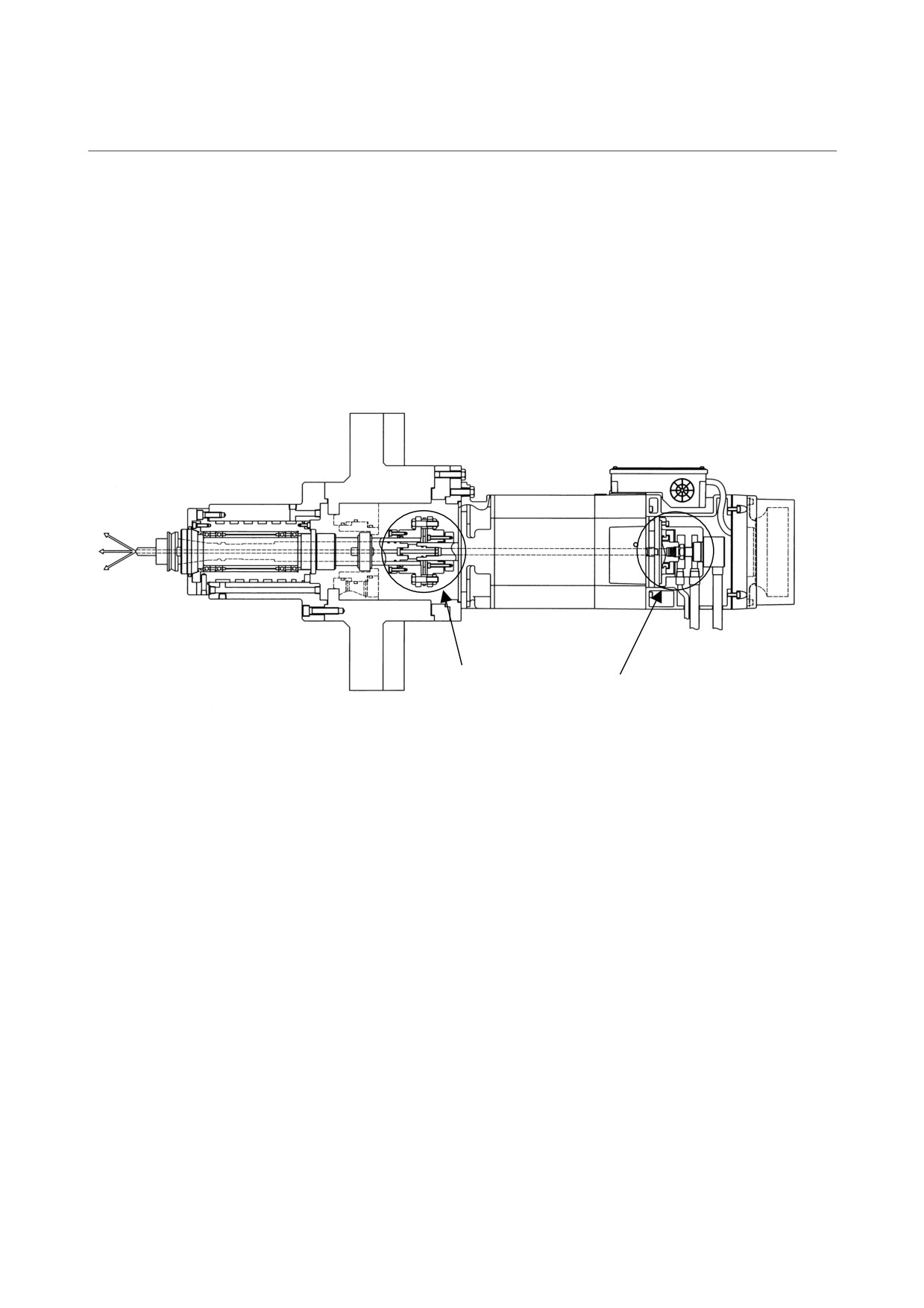
<1> Check whether coolant is always leaking out from the drains
or notch of the rotary joint support housing. (See Fig. 2.)
<2> Check whether the vibration acceleration of the motor
turning at the maximum speed exceeds 0.5 G. (See Fig. 3.)
<3> Check whether coolant leaks out from the coolant joint of the
coupling. (See Fig. 4.)
<4> Check for backlash in the coupling.
Coupling
Rotary joint support housing
Fig. 1 Example of using the coolant through spindle motor
- 230 -
2. SPINDLE MOTOR
B-65165E/02
MOTOR MAINTENANCE
MAINTENANCE
Motor body
Rotary joint support housing
Pickup
Drain
Vibrometer
Notch
Spare drain
Fig. 2 Rotary joint support housing
Fig. 3 Measuring vibration acceleration
Convex type
Concave type
Coolant joint
Fig. 4 Example of a coolant joint
- 231 -
2. SPINDLE MOTOR
MAINTENANCE
TROUBLESHOOTING
B-65165E/02
2.2
MAINTENANCE PARTS
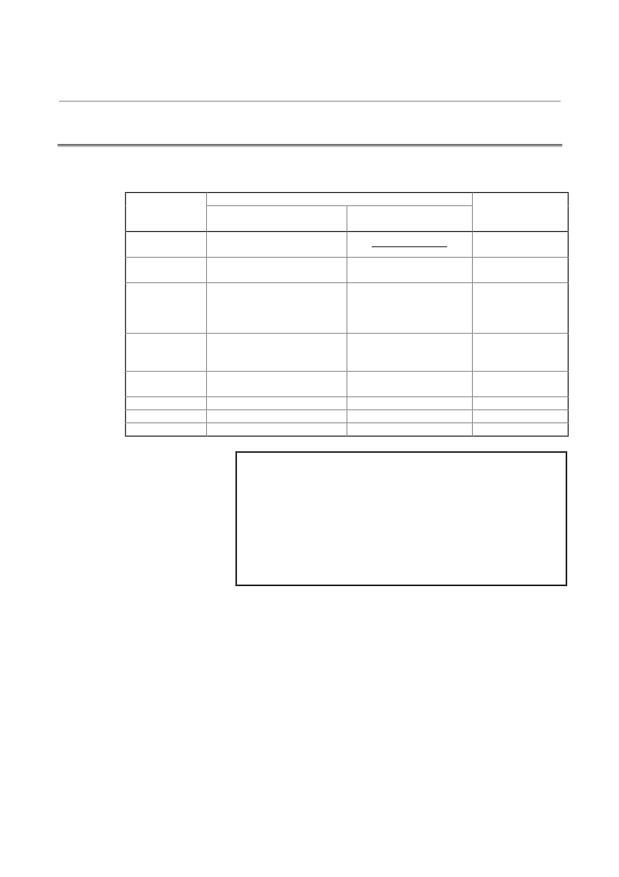
(1) Parts of the terminal box (α, αP, αC, and αHV series)
Terminal box assembly
Model
When the motor drawing No. ends
When the motor drawing No.
Lid of terminal box
with B
0
or B
9
(Note 1)
ends with B
3
(Note 1)
α1, α1.5,
A290-0850-T400
A290-0853-V410
αC1, αC1.5
α2, α3,
A290-0853-T400
A290-0853-T401
A290-0853-V410
αC2, αC3
α6 to α15
αP8 to αP22
A290-0854-T400
A290-0854-T401
A290-0854-V410
α6HV to α15HV
αC6 to αC15
α18, α22
α18HV, α22HV
A290-0731-T420
A290-0731-T421
A290-0731-V410
αC18, αC22
α30, α40
A290-0860-T400
A290-0860-T401
A290-1040-X402
α30HV, α40HV
αP30 to αP50
A290-0731-T455
A290-0731-T456
A290-0731-V410
αP60
A290-0833-T400
A290-0833-T401
A290-1040-X402
α60HV
A290-0860-T403
A290-0860-T404
A290-1040-X402
NOTE
1
For example, drawing number A06B-0856-B100
ends with B
0
, and A06B-0856-B130 ends with
B
3
2
The above table may not apply to motors of which
motor drawing number ends with B9
. Contact
your FANUC service representative.
3
The above table may not apply to maintenance parts
of high-speed models.
- 232 -
2. SPINDLE MOTOR
B-65165E/02
MOTOR MAINTENANCE
MAINTENANCE
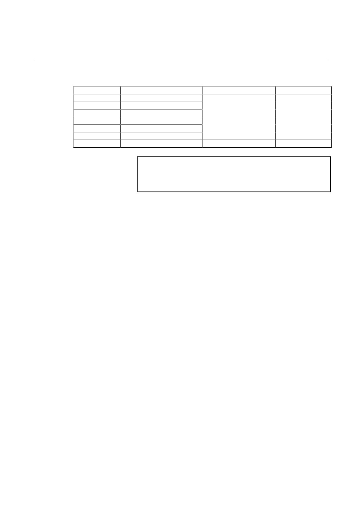
(2) Terminal box drawing numbers (αT series)
Model name
Motor drawing No.(Note 4)
Terminal box assembly
Lid of terminal box
αT1.5/15000
A06B-0871-B927
αT2/15000
A06B-0869-B927
A290-0853-T408
A290-0853-V410
αT3/12000
A06B-0853-B927
αT6/12000
A06B-0854-B927
αT8/12000
A06B-0855-B927
A290-0854-T408
A290-0854-V410
αT15/10000
A06B-0857-B927, B928
αT22/10000
A06B-0859-B927, B928
A290-0731-T457
A290-0731-V410
NOTE
4
The above table may not apply to the motors other
than the drawing numbers listed in the above table.
Contact your FANUC service representative.
- 233 -
2. SPINDLE MOTOR
MAINTENANCE
TROUBLESHOOTING
B-65165E/02
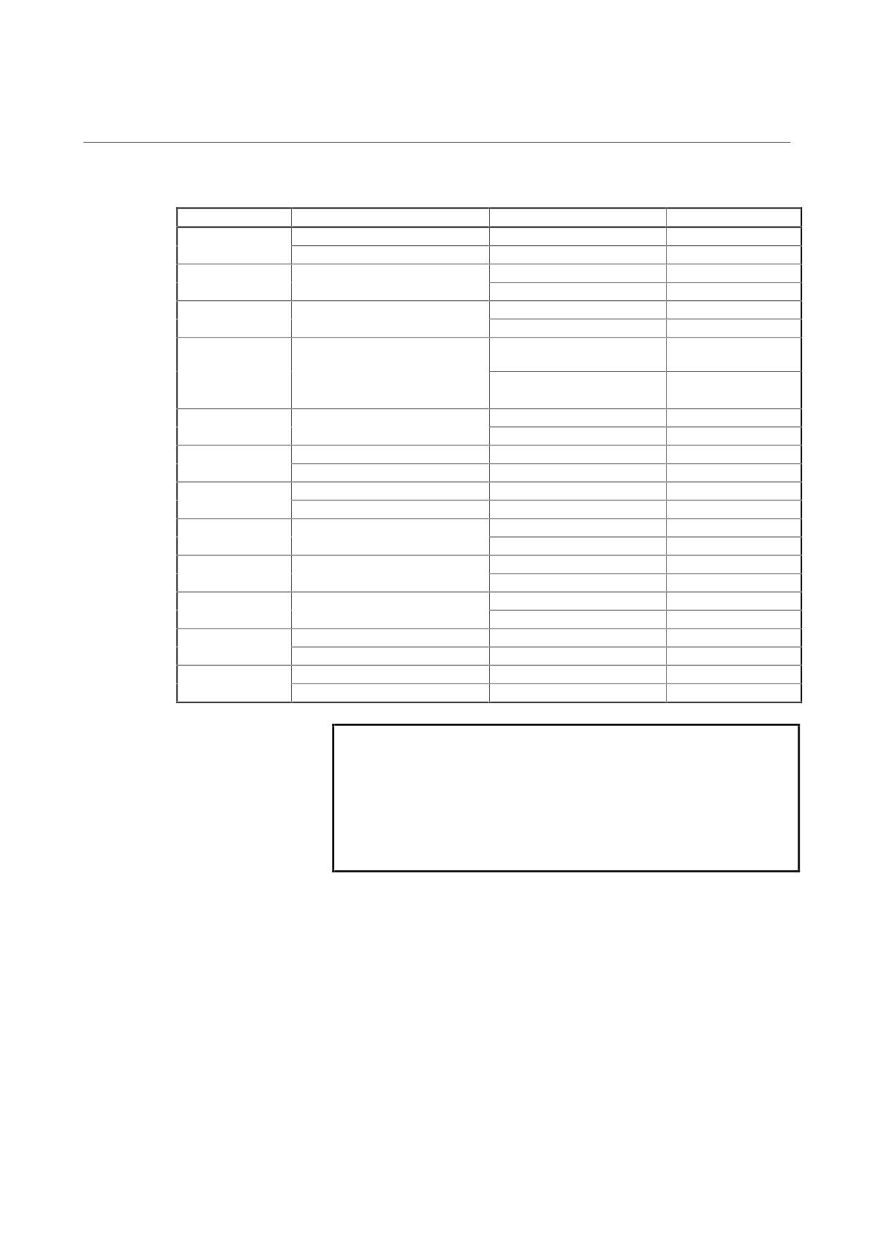
(3) Fan motor parts (α, αP, αC, and αHV series)
Model
Fan cover
Fan motor
Air flow direction
α1, α1.5
A290-0850-T500(Note 5)
A90L-0001-0491/R
Backward
αC1, αC1.5
A290-0850-T501(Note 5)
A90L-0001-0491/F
Forward
α2, α3
A90L-0001-0442/R
Backward
A290-0853-X501
αC2, αC3
A90L-0001-0442/F
Forward
α6, α8, αP8
A90L-0001-0443/R
Backward
A290-0854-X501
αC6, αC8
A90L-0001-0443/F
Forward
α12, α15, αP12,
A90L-0001-0444/RS
Backward
αP15
A290-0856-X501
αC12, αC15,
A90L-0001-0444/FS
Forward
αP18, αP22
α18, α22
A90L-0001-0444/R
Backward
A290-0856-X501
αC18, αC22
A90L-0001-0444/F
Forward
α30, α40
A290-0731-T510(Note 5)
A90L-0001-0318/R
Backward
αP30, αP40
A290-0731-T511(Note 5)
A90L-0001-0318/F
Forward
A290-0832-T500(Note 5)
A90L-0001-0319/R
Backward
αP50, αP60
A290-0832-T501(Note 5)
A90L-0001-0319/F
Forward
A90L-0001-0457/R
Backward
α6HV, α8HV
A290-0854-X501
A90L-0001-0457/F
Forward
A90L-0001-0458/RS
Backward
α12HV, α15HV
A290-0856-X501
A90L-0001-0458/FS
Forward
A90L-0001-0458/R
Backward
α18HV, α22HV
A290-0856-X501
A90L-0001-0458/F
Forward
A290-0780-T510(Note 4)
A90L-0001-0399/R
Backward
α30HV, α40HV
A290-0780-T511(Note 4)
A90L-0001-0399/F
Forward
A290-0883-T500(Note 4)
A90L-0001-0400/R
Backward
α60HV
A290-0883-T501(Note 4)
A90L-0001-0400/F
Forward
NOTE
5
These drawing numbers include fan motors.
6
The above table may not apply to motors of which
motor drawing number ends with B9
. Contact
your FANUC service representative.
7
The above table may not apply to maintenance parts
of high-speed models.
- 234 -
2. SPINDLE MOTOR
B-65165E/02
MOTOR MAINTENANCE
MAINTENANCE
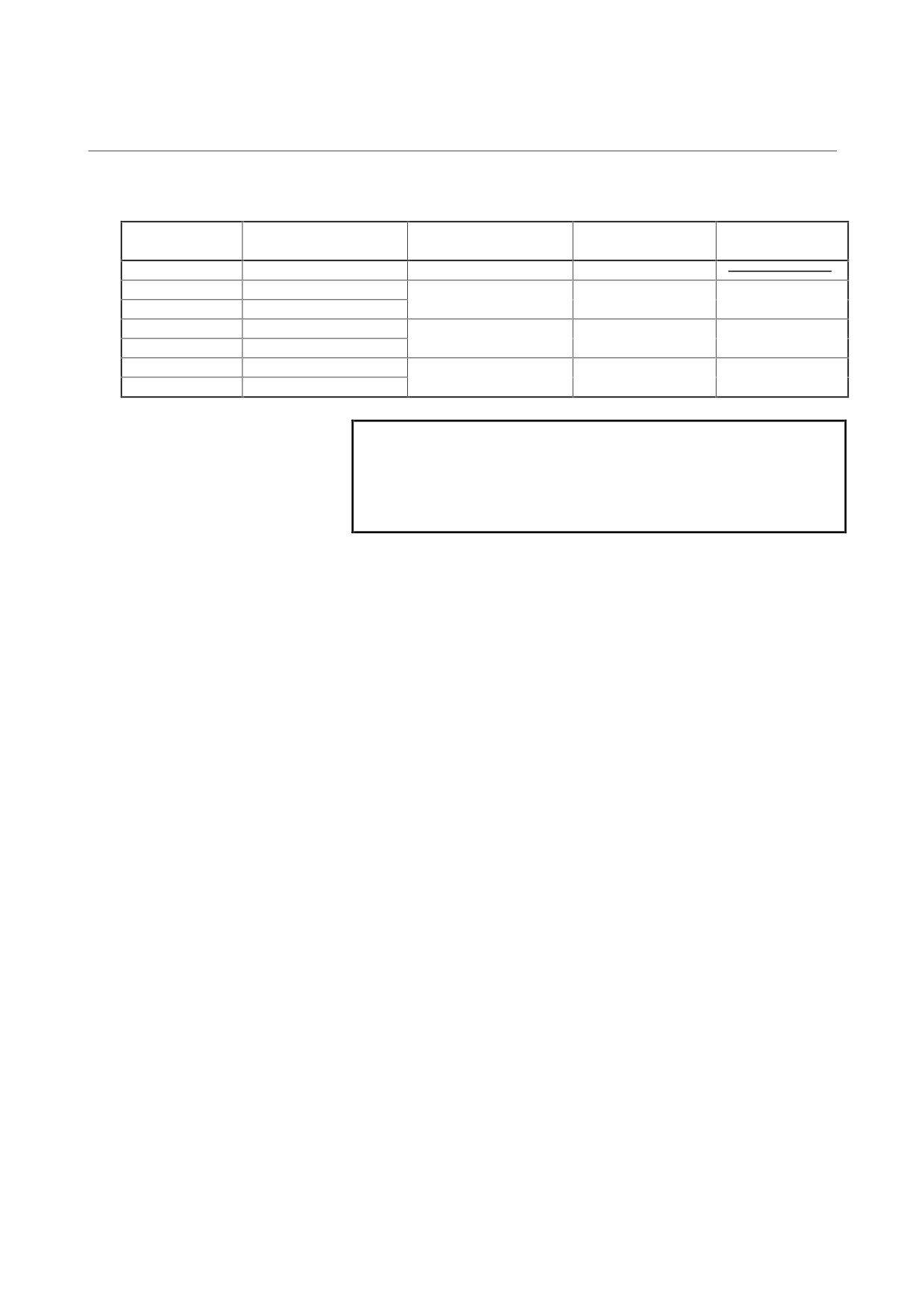
(4) Fan motor parts (αT series)
Motor drawing
Model name
Fan cover
Fan motor
Fan base
No.(Note 9)
αT1.5/15000
A06B-0871-B927
A290-0850-T504(Note 8)
A90L-0001-0491/RL
αT2/15000
A06B-0869-B927
A290-0853-X501
A90L-0001-0442/RL
A290-0853-X507
αT3/12000
A06B-0853-B927
αT6/12000
A06B-0854-B927
A290-0854-X501
A90L-0001-0443/RL
A290-0854-X507
αT8/12000
A06B-0855-B927
αT15/10000
A06B-0857-B927, B928
A290-0856-X501
A90L-0001-0444/RL
A290-0856-X504
αT22/10000
A06B-0859-B927, B928
NOTE
8
These drawing numbers include fan motors.
9
The above table may not apply to the motors other
than the drawing numbers listed in the above table.
Contact your FANUC service representative.
- 235 -
2. SPINDLE MOTOR
MAINTENANCE
TROUBLESHOOTING
B-65165E/02
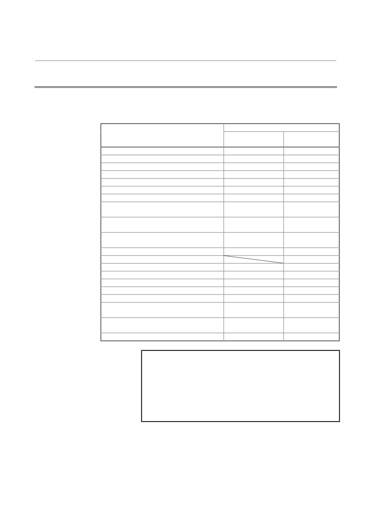
2.3
PERMISSIBLE RADIAL LOAD
Use motor output axes under the permissible radial load listed below or
less:
Permissible radial load
Model
Center of output
Output axis end
axis
〈0.5
294 N (30 kgf)
323 N (33 kgf)
α1, αC1
392 N (40 kgf)
441 N (45 kgf)
α1.5, αC1.5
882 N (90 kgf)
980 N (100 kgf)
α2, αC2
882 N (90 kgf)
999 N (102 kgf)
α3, αC3
1470 N (150 kgf)
1607 N (164 kgf)
α6, α6HV, αC6
1960 N (200 kgf)
2205 N (225 kgf)
α8, αP8, α8HV, αC8
2940 N (300 kgf)
3371 N (344 kgf)
α12, α15, αP12, αP15
2940 N (300 kgf)
3410 N (348 kgf)
α12HV, α15HV, αC12, αC15
α18, α22, αP18, αP22
4410 N (450 kgf)
4988 N (509 kgf)
α18HV, α22HV, αC18, αC22
α30, α40, αP30, αP40
5390 N (550 kgf)
6134 N (626 kgf)
α30HV, α40HV
αP50
10780 N (1100 kgf)
12299 N (1255 kgf)
αP60, α60HV
19600 N (2000 kgf)
α1/15000
392 N (40 kgf)
441 N (45 kgf)
α2/15000
490 N (50 kgf)
558 N (57 kgf)
α3/12000
980 N (100 kgf)
1068 N (109 kgf)
α6/12000
1470 N (150 kgf)
1656 N (169 kgf)
α8/8000, αP8/8000
1960 N (200 kgf)
2244 N (229 kgf)
α12/8000, α15/8000
2450 N (250 kgf)
2842 N (290 kgf)
αP12/8000, αP15/8000
α18/8000, α22/8000
2940 N (300 kgf)
3332 N (340 kgf)
αP18/8000, αP22/8000
α30/8000, αP30/8000, αP40/8000
5390 N (550 kgf)
6134 N (626 kgf)
NOTE
1
When using a belt, adjust the tension of the belt so
that the permissible value listed above is not
exceeded.
2
When the belt tension center is positioned beyond
the end of an output axis, the permissible load
becomes smaller than that at the end of the output
axis.
- 236 -