FANUC AC SERVO MOTOR ai series, AC SPINDLE MOTOR ai series, SERVO AMPLIFIER ai series. MAINTENANCE MANUAL - page 3
4.CONFIRMATION OF THE
OPERATION
START-UP PROCEDURE
B-65285EN/04
(3) Observation of phase U current in the αiSP 11
Setting of observation data
+5 V
Data No.
218
100 A
Shift amount
8
Shift direction
0 (shifted left)
Offset
1 (provided)
0 V
33.3 A/1 V
-5 V
4.3.7
Checking Parameters Using the Spindle Check Board
4.3.7.1 Overview
By using the check board, you can check parameter values transferred to the Spindle Amplifier. Specify
parameter numbers using the four setting switches on the check board, and check parameter values on the
five-digit indicator.
4.3.7.2 Checking parameters
<1> Press the four setting switches at the same time for at least one second. "FFFFF" will be displayed on
the indicator.
<2> Turn off the switches and press the "MODE" switch. "d-00" will be displayed on the indicator and the
system will enter the mode for measuring internal data.
<3> With "0" set for "d-00", press the "MODE" and "DATA SET" switches at the same time for at least one
second. "CCCCC" will be displayed on the indicator.
<4> Turn off the switches and press the "MODE" switch. "F-xxx" will be displayed on the indicator and the
system will enter the mode for checking spindle parameters (F-mode). (Even in this mode, the motor
can be operated normally.)
<5> Press the "UP" or "DOWN" switch while holding down the "MODE" switch (with "F-xxx" displayed).
The number of "F-xxx" increases or decreases. Set the internal number of a parameter you want to
check. For correspondences between the parameter internal numbers and NC parameter numbers, see
the parameter list in the appendix to the parameter manual.
<6> Turn off the switches. The parameter value corresponding to the set internal number is displayed for
about one second. (Bit parameter values are displayed in hexadecimal.)
4.3.8
Observing Data Using the SERVO GUIDE
4.3.8.1 Overview
Using the servo adjustment tool, SERVO GUIDE, enables you to observe internal data for the spindle.
This subsection describes the spindle data that can be observed using the SERVO GUIDE. It also presents
examples of observed data. Refer to online help for detailed explanations about how to use the SERVO
GUIDE.
4.3.8.2 Usable series and editions
Series 9D50/B(02) and subsequent editions
Series 9D53/A(01) and subsequent editions
Series 9D70/A(01) and subsequent editions
Series 9D80/A(01) and subsequent editions
Series 9D90/A(01) and subsequent editions
Series 9DA0/A(01) and subsequent editions
- 42 -
4.CONFIRMATION OF THE
B-65285EN/04
START-UP PROCEDURE
OPERATION
4.3.8.3 List of spindle data that can be observed using the SERVO
GUIDE
The following table lists the spindle data that can be observed using the SERVO GUIDE.
Data type
Description
SPEED
Motor speed
INORM
Motor current amplitude
TCMD
Torque command
VCMD
Motor speed command
VERR
Speed deviation
ERR
Position error
(9D50/11 and subsequent editions *1)
ERRC
Position error (CNC)
ORERR
Position error at orientation
WMDAT
Move command for an individual position loop
SYNC
Synchronization error
(9D50/11 and subsequent editions *1)
PCPOS
Cumulative position feedback value
MCMD
Move command for an individual communication cycle
ERR2
Position error 2
ERR2C
Position error 2(CNC)
(9D50/11 and subsequent editions *1)
CSPOS
Cumulative position feedback value
SPCMD
Speed command data from the CNC
SPSPD
Spindle speed
(9D50/11 and subsequent editions *1)
SPCT1
Spindle control signal 1
SPCT2
Spindle control signal 2
SPCT3
Spindle control signal 3
(9D50/11 and subsequent editions *1)
SPST1
Spindle status signal 1
SPST2
Spindle status signal 2
ORSEQ
Orientation sequence data
SFLG1
Spindle flag 1
(9D50/11 and subsequent editions *1)
SPPOS
Spindle position data
(9D50/12 and subsequent editions *2)
LMDAT
Load meter data 1
(9D50/11 and subsequent editions *1)
DTRQ
Spindle load torque (Unexpected disturbance torque detection function) 1
(9D50/11 and subsequent editions *1)
FREQ
Frequency of disturbance torque (Disturbance input function) 1
(9D50/11 and subsequent editions *1)
GAIN
Gain data (Disturbance input function) 1
(9D50/11 and subsequent editions *1)
MTTMP
Motor winding temperature 1
(9D50/11 and subsequent editions *1)
MFBDF
Motor sensor feedback incremental data 1
(9D50/11 and subsequent editions *1)
(For amplitude ratio and phase difference compensation)
SFBDF
Spindle sensor feedback incremental data 1
(9D50/11 and subsequent editions *1)
(For amplitude ratio and phase difference compensation)
PA1
AD data 1 of A phase of motor sensor
(9D50/11 and subsequent editions *1)
PB1
AD data 1 of B phase of motor sensor
(9D50/11 and subsequent editions *1)
PA2
AD data 1 of A phase of spindle sensor
(9D50/11 and subsequent editions *1)
PB2
AD data 1 of B phase of spindle sensor
(9D50/11 and subsequent editions *1)
VDC
DC link voltage 1
(9D50/11 and subsequent editions *1)
SFERR
Semi-full error 1 (Dual position feedback)
(9D50/11 and subsequent editions *1)
SMERR
Semi-closed side error 1 (Dual position feedback)
(9D50/11 and subsequent editions *1)
SPACC
Spindle acceleration data 1
(9D50/20 and subsequent editions *4)
- 43 -
4.CONFIRMATION OF THE
OPERATION
START-UP PROCEDURE
B-65285EN/04
NOTE
*1 Available with 9D53/03 and subsequent editions for series 9D53, 9D70/02 and
subsequent editions for series 9D70, 9D80/01 and subsequent editions for series
9D80, and 9D90/01 and subsequent editions for series 9D90.
*2 Available with 9D53/04 and subsequent editions for series 9D53, 9D70/03and
subsequent editions for series 9D70, 9D80/01and subsequent editions for series
9D80, and 9D90/0 and subsequent editions for series 9D90.
*3 To observe data marked with *1 and *2, the SERVO GUIDE Ver. 3.0 or later is
required.
*4 Available with 9D70/10 and subsequent editions for series 9D70, 9D80/04 and
subsequent editions for series 9D80, and 9D90/01 and subsequent editions for
series 9D90.
To observe this data, the SERVO GUIDE Ver. 4.10 or later is required.
4.3.8.4 About the spindle control and spindle status signals
As stated in the previous item, the SERVO GUIDE can be used to observe the PMC signals (spindle control
signals 1 and 2 and spindle status signals 1 and 2) used by the spindle.
Listed below is the data configuration for spindle control signals 1 and 2 and spindle status signals 1 and 2.
Refer to Chapter 3, "PMC Signals (CNC ↔ PMC)" of "FANUC AC SPINDLE MOTOR αi series
PARAMETER MANUAL" (B-65280EN) for explanations about each signal.
(a) Spindle control signal 1 (SPCT1)
#15
#14
#13
#12
#11
#10
#9
#8
RCH
RSL
INTG
SOCN
MCFN
SPSL
*ESP
ARST
#7
#6
#5
#4
#3
#2
#1
#0
MRDY
ORCM
SFR
SRV
CTH1
CTH2
TLMH
TLML
(b) Spindle control signal 2 (SPCT2)
#15
#14
#13
#12
#11
#10
#9
#8
DSCN
SORSL
MPOF
#7
#6
#5
#4
#3
#2
#1
#0
RCHHG
MFNHG
INCMD
OVR
NRRO
ROTA
INDX
(c) Spindle control signal 3 (SPCT3)
#15
#14
#13
#12
#11
#10
#9
#8
#7
#6
#5
#4
#3
#2
#1
#0
(d) Spindle status signal 1 (SPST1)
#15
#14
#13
#12
#11
#10
#9
#8
RCFN
RCHP
CFIN
CHP
#7
#6
#5
#4
#3
#2
#1
#0
ORAR
TLM
LDT2
LDT1
SAR
SDT
SST
ALM
(e) Spindle status signal 2 (SPST2)
#15
#14
#13
#12
#11
#10
#9
#8
#7
#6
#5
#4
#3
#2
#1
#0
EXOF
SOREN
INCST
PC1DT
- 44 -
4.CONFIRMATION OF THE
B-65285EN/04
START-UP PROCEDURE
OPERATION
4.3.8.5 Example of observing data
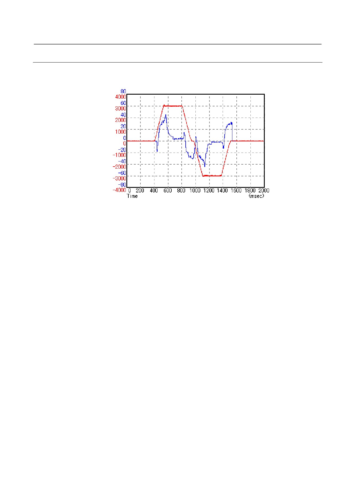
The following figure shows an example of data (synchronization error and motor speed at rigid tapping)
observed using the SERVO GUIDE.
DRAW1 : SYNC
DRAW2 : SPEED
DRAW1 : SYNC (synchronization error) *1
DRAW2 : SPEED (motor speed)
*1 The synchronization error is servo axis output data.
- 45 -
II. TROUBLESHOOTING
B-65285EN/04
TROUBLESHOOTING
1.OVERVIEW
1 OVERVIEW
This part describes the troubleshooting procedure for each amplifier. Read the section related to your
current trouble to locate it and take an appropriate action.
First, check the alarm number and STATUS display indicated on your amplifier with each list (alarm
numbers in the list are those for the CNC) in Chapter 2 to find the corresponding detailed information in
Chapter 3. Then take an appropriate action according to the detailed information.
- 49 -
2.ALARM NUMBERS AND
BRIEF DESCRIPTIONS
TROUBLESHOOTING
B-65285EN/04
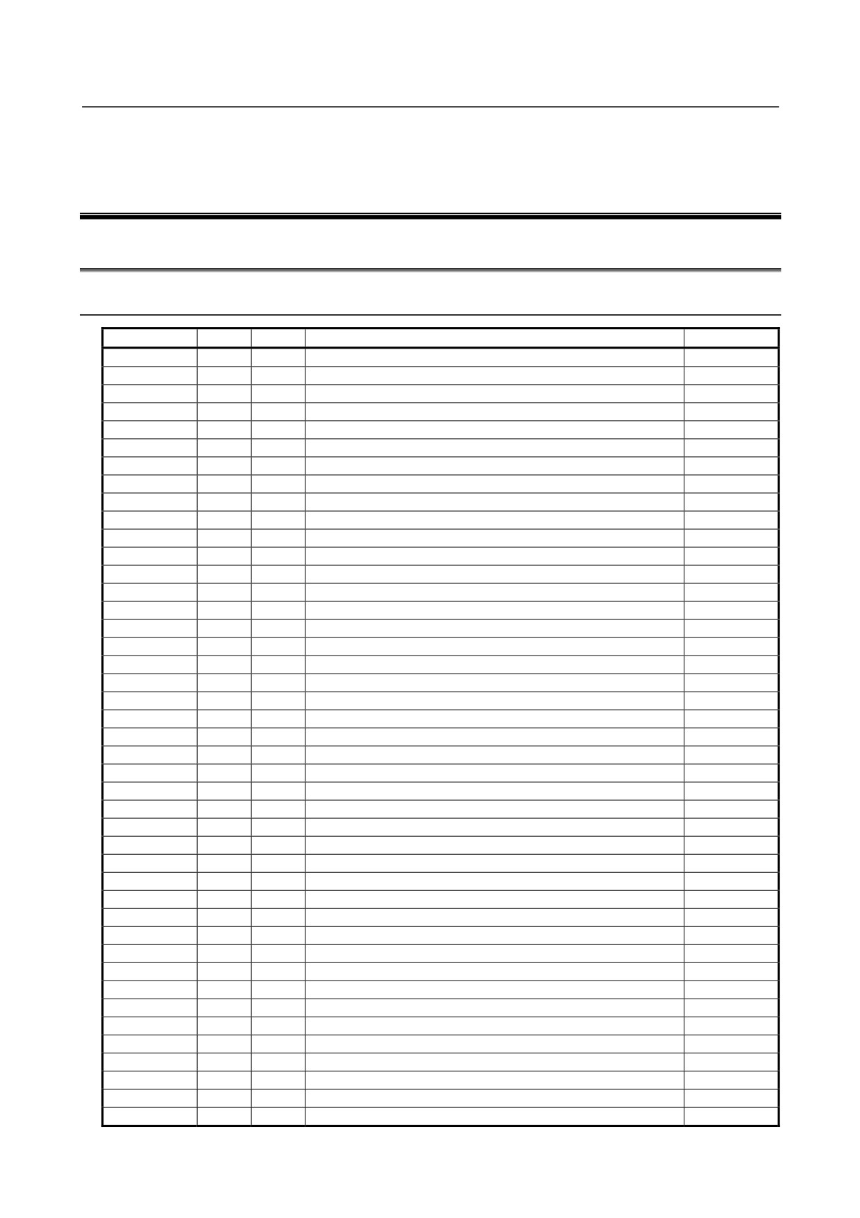
2 ALARM NUMBERS AND BRIEF
DESCRIPTIONS
2.1
FOR Series 15i
2.1.1
Servo Alarm
Alarm No.
SV
PS
Description
Remarks
SV0027
Invalid digital servo parameter setting
3.3.6
SV0361
Pulsecoder phase error (built-in)
3.3.7 (1)
SV0364
Soft phase alarm (built-in)
3.3.7 (1)
SV0365
LED error (built-in)
3.3.7 (1)
SV0366
Pulse error (built-in)
3.3.7 (1)
SV0367
Count error (built-in)
3.3.7 (1)
SV0368
Serial data error (built-in)
3.3.7 (3)
SV0369
Data transfer error (built-in)
3.3.7 (3)
SV0380
LED error (separate)
3.3.7 (2)
SV0381
Pulsecoder phase error (separate)
3.3.7 (2)
SV0382
Count error (separate)
3.3.7 (2)
SV0383
Pulse error (separate)
3.3.7 (2)
SV0384
Soft phase alarm (separate)
3.3.7 (2)
SV0385
Serial data error (separate)
3.3.7 (3)
SV0386
Data transfer error (separate)
3.3.7 (3)
SV0387
Sensor error (separate)
3.3.7 (2)
SV0421
Excessive semi-full error
3.3.8
SV0430
Servo motor overheat
3.3.5
SV0431
3
Converter: main circuit overload
3.1.3
SV0432
6
Converter: control power supply undervoltage
3.1.6
SV0433
4
Converter: DC link undervoltage
3.1.4
SV0434
2
Inverter: control power supply undervoltage
3.2
SV0435
5
Inverter: DC link undervoltage
3.2
SV0436
Soft thermal (OVC)
3.3.3
SV0437
1
Converter: input circuit overcurrent
3.1.1
SV0438
b
Inverter: motor current alarm (L axis)
3.2
SV0438
c
Inverter: motor current alarm (M axis)
3.2
SV0438
d
Inverter: motor current alarm (N axis)
3.2
SV0439
7
Converter: DC link overvoltage
3.1.7
SV0440
H
Converter: Excessive deceleration power
3.1.11
SV0441
Current offset error
3.3.8
SV0442
5
Converter: DC link precharge failure
3.1.5
SV0443
2
Converter: cooling fan stopped
3.1.2
SV0444
1
Inverter: internal cooling fan stopped
3.2
SV0445
Soft disconnection alarm
3.3.4
SV0446
Hard disconnection alarm
Not issued
SV0447
Hard disconnection alarm (separate)
3.3.4
SV0448
Feedback mismatch alarm
3.3.8
SV0449
8.
Inverter: IPM alarm (L axis)
3.2
SV0449
9.
Inverter: IPM alarm (M axis)
3.2
SV0449
A.
Inverter: IPM alarm (N axis)
3.2
SV0600
8
Inverter: DC link current alarm (L axis)
3.2
SV0600
9
Inverter: DC link current alarm (M axis)
3.2
- 50 -
2.ALARM NUMBERS AND
B-65285EN/04
TROUBLESHOOTING
BRIEF DESCRIPTIONS
Alarm No.
SV
PS
Description
Remarks
SV0600
A
Inverter: DC link current alarm (N axis)
3.2
SV0601
F
Inverter: cooling fan stopped of the radiator
3.2
SV0602
6
Inverter: overheat
3.2
SV0603
8.
Inverter: IPM alarm (OH) (L axis)
3.2
SV0603
9.
Inverter: IPM alarm (OH) (M axis)
3.2
SV0603
A.
Inverter: IPM alarm (OH) (N axis)
3.2
SV0604
P
Communication error between amplifiers
3.2
SV0605
8
Converter: Excessive regenerative power
3.1.8
SV0606
A
Converter: cooling fan stopped of the radiator
3.1.9
SV0607
E
Open phase in the converter main power supply
3.1.10
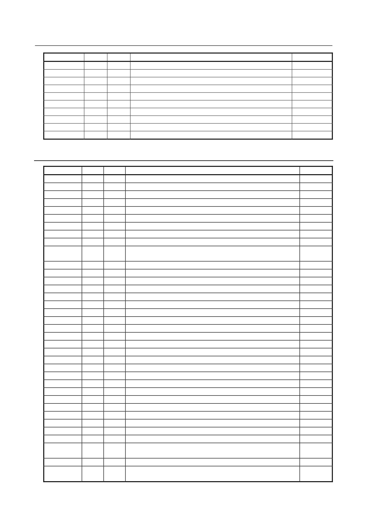
2.1.2
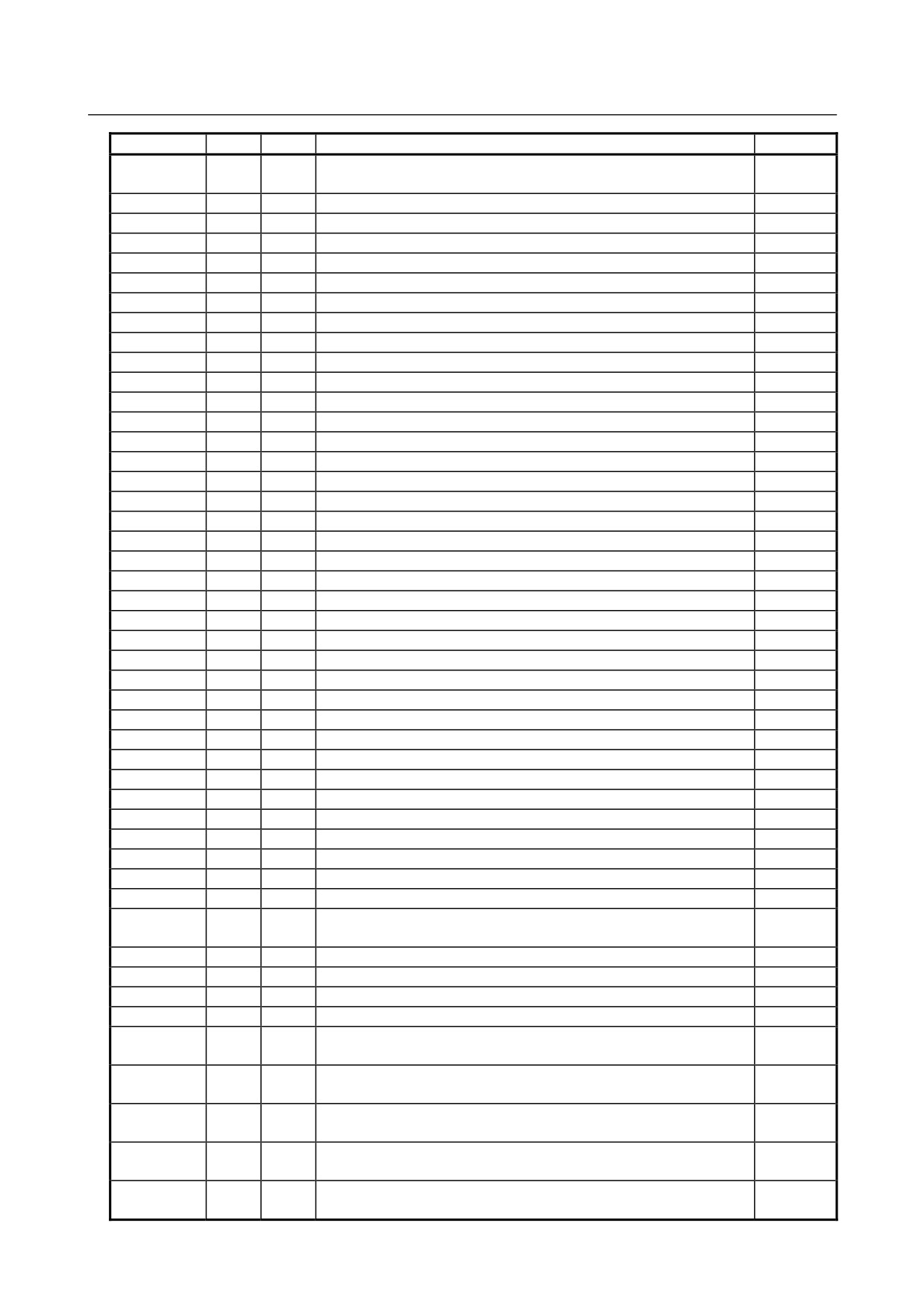
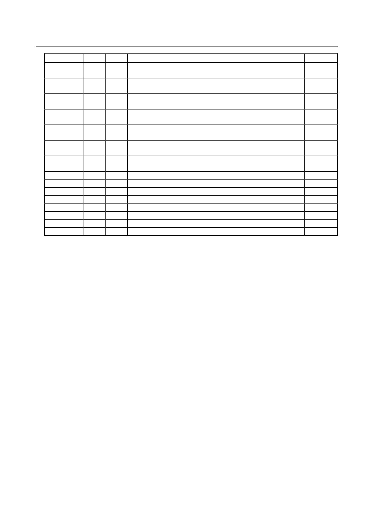
Spindle Alarm
Alarm No.
SP
PS
Description
Remarks
SP0001
01
Motor overheat
3.4.1
SP0002
02
Excessive speed deviation
3.4.2
SP0003
03
DC link fuse blown
3.4.3
SP0004
04
E
Open phase in the converter main power supply
3.1.10
SP0006
06
Temperature sensor disconnected
3.4.4
SP0007
07
Excessive speed
3.4.5
SP0009
09
Main circuit overload/IPM overheat
3.4.6
SP0010
10
Low power supply input voltage
3.4.7
SP0011
11
7
Converter: DC link overvoltage
3.1.7
3.4.8
SP0012
12
DC link overcurrent/IPM alarm
3.5.1
SP098x
13
CPU internal data memory error
3.4.9
SP0014
14
Amplifier ID not registered
3.4.10
SP0015
15
Output switching/spindle switching alarm
3.4.11
SP0017
17
Amplifier ID data error
3.4.13
SP098x
18
Program sum check error
3.4.14
SP098x
19
Excessive offset of the phase U current detection circuit
3.4.15
SP098x
20
Excessive offset of the phase V current detection circuit
3.4.15
SP0021
21
Position sensor polarity setting incorrect
3.4.16
SP0022
22
Spindle amplifier current overload
3.4.17
SP022x
24
Serial transfer data error
3.4.18
SP0027
27
Position coder disconnected
3.4.19
SP0029
29
Short-period overload
3.4.20
SP0030
30
1
Overcurrent in the converter input circuit
3.1.1
SP0031
31
Motor lock alarm
3.4.21
SP0032
32
Serial communication LSI RAM error
3.4.22
SP0033
33
5
Converter: DC link precharge failure
3.1.5
SP0034
34
Parameter data out of the specifiable range
3.4.23
SP0035
35
Gear ratio parameter error
3.5.2
SP0036
36
Error counter overflow
3.4.24
SP0037
37
Speed detector parameter error
3.4.25
SP0041
41
Position coder one-rotation signal detection error
3.4.26
SP0042
42
Position coder one-rotation signal not detected
3.4.27
SP0043
43
Position coder signal for differential speed mode disconnected
3.4.28
Position sensor one-rotation signal detection error during thread
3.4.29
SP0046
46
cutting
SP0047
47
Position coder signal error
3.4.30
49
Overflow of converted motor speed for differential spindle speed
3.4.31
SP0049
control
- 51 -
2.ALARM NUMBERS AND
BRIEF DESCRIPTIONS
TROUBLESHOOTING
B-65285EN/04
Alarm No.
SP
PS
Description
Remarks
Excessive speed command calculation value during spindle
3.1.4
SP0050
50
synchronization
SP0051
51
4
Converter: DC link undervoltage
3.4.33
SP0052
52
ITP signal error I
3.4.33
SP0053
53
ITP signal error II
3.4.34
SP0054
54
Current overload alarm
3.4.35
SP0055
55
Abnormal switching status of power leads
3.4.36
SP0056
56
Internal cooling fan stopped
3.1.11
SP0057
57
H
Converter: excessive deceleration power
3.1.3
SP0058
58
3
Converter: main circuit overload
3.1.2
SP0059
59
2
Converter: cooling fan stopped
3.4.37
SP0061
61
Excessive semi-closed loop/closed loop position error alarm
3.4.38
SP0065
65
Abnormal travel distance in magnetic pole determination operation
3.4.39
SP0066
66
Communication alarm between spindle and amplifier
3.4.45
SP0069
69
Safety speed exceeded
3.4.46
SP0070
70
Abnormal axis data
3.4.47
SP0071
71
Abnormal safety parameter
3.4.51
SP0072
72
Motor speed mismatch
3.4.52
SP0073
73
Motor sensor disconnected
3.4.53
SP0074
74
CPU test alarm
3.4.54
SP0075
75
CRC test alarm
3.4.55
SP0076
76
Safety function not executed
3.4.56
SP0077
77
Axis number mismatch
3.4.57
SP0078
78
Safety parameter mismatch
3.4.58
SP0079
79
Abnormal initial test operation
3.4.59
SP0080
80
Destination amplifier error in inter-spindle amplifier communication
3.4.60
SP0081
81
Motor sensor one-rotation signal detection error
3.4.61
SP0082
82
Motor sensor one-rotation signal not detected
3.4.62
SP0083
83
Motor sensor signal error
3.4.63
SP0084
84
Spindle sensor disconnected
3.4.64
SP0085
85
Spindle sensor one-rotation signal detection error
3.4.83
SP0086
86
Spindle sensor one-rotation signal not detected
3.4.83
SP0087
87
Spindle sensor signal error
3.4.65
SP0088
88
Cooling fan stopped of the radiator
3.4.65
SP0089
89
Sub module SM (SSM) error
3.4.65
SP0090
90
Unexpected rotation alarm
3.4.66
SP0091
91
Pole position count miss alarm
3.1.6
SP0092
92
Velocity command-dependent overspeed alarm
3.1.8
SP0097
3.1.9
(MODEL A)
Other spindle amplifier alarm
SP0097x
A
Program ROM error
3.4.67
SP0097x
A1
Program ROM error
3.4.67
SP0097x
A2
Program ROM error
3.4.67
SP0098
Other converter alarm
3.4.68
SP0098
3.4.74
(MODEL A)
b0
Communication error between amplifiers
SP0098
3.4.76
(MODEL A)
b1
6
Converter: control power supply low voltage
SP0098
3.4.77
(MODEL A)
b2
8
Converter: excessive regenerative power
SP0098
3.4.78
(MODEL A)
b3
2
Converter: cooling fan stopped of the radiator
SP0110
3.4.79
(MODEL B)
b0
Communication error between amplifiers
- 52 -
2.ALARM NUMBERS AND
B-65285EN/04
TROUBLESHOOTING
BRIEF DESCRIPTIONS
Alarm No.
SP
PS
Description
Remarks
SP0111
3.4.80
(MODEL B)
b1
6
Converter: control power supply low voltage
SP0112
3.4.81
(MODEL B)
b2
8
Converter: excessive regenerative power
SP0113
3.4.82
(MODEL B)
b3
A
Converter: cooling fan stopped of the radiator
SP0120
(MODEL B)
C0
Communication data alarm
3.4.51
SP0121
(MODEL B)
C1
Communication data alarm
3.4.51
SP0122
(MODEL B)
C2
Communication data alarm
3.4.51
SP0123
(MODEL B)
C3
Spindle switching circuit error
3.4.52
SP0130
d0
Speed polarity error in torque tandem operation
3.4.74
SP0132
d2
Serial data error
3.4.76
SP0133
d3
Data transfer error
3.4.77
SP0134
d4
Soft phase alarm
3.4.78
SP0137
d7
Device communication error
3.4.79
SP0139
d9
Pulse error alarm
3.4.80
SP0140
E0
Count error alarm
3.4.81
SP0141
E1
Serial sensor one-rotation signal not detected
3.4.82
- 53 -
2.ALARM NUMBERS AND
BRIEF DESCRIPTIONS
TROUBLESHOOTING
B-65285EN/04
2.2
FOR Series 16i, 18i, 20i, 21i, 0i, AND Power Mate i
2.2.1
Servo Alarm
Alarm No.
SV
PS
Description
Remarks
361
Pulsecoder phase error (built-in)
3.3.7 (1)
364
Soft phase alarm (built-in)
3.3.7 (1)
365
LED error (built-in)
3.3.7 (1)
366
Pulse error (built-in)
3.3.7 (1)
367
Count error (built-in)
3.3.7 (1)
368
Serial data error (built-in)
3.3.7 (3)
369
Data transfer error (built-in)
3.3.7 (3)
380
LED error (separate)
3.3.7 (2)
381
Pulsecoder phase error (separate)
3.3.7 (2)
382
Count error (separate)
3.3.7 (2)
383
Pulse error (separate)
3.3.7 (2)
384
Soft phase alarm (separate)
3.3.7 (2)
385
Serial data error (separate)
3.3.7 (3)
386
Data transfer error (separate)
3.3.7 (3)
387
Sensor error (separate)
3.3.7 (2)
417
Invalid parameter
3.3.6
421
Excessive semi-full error
3.3.8
430
Servomotor overheat
3.3.5
431
3
Converter: main circuit overload
3.1.3
432
6
Converter: control undervoltage
3.1.6
433
4
Converter: DC link undervoltage
3.1.4
434
2
Inverter: control power supply undervoltage
3.2
435
5
Inverter: DC link undervoltage
3.2
436
Soft thermal (OVC)
3.3.3
437
1
Converter: input circuit overcurrent
3.1.1
438
b
Inverter: motor current alarm (L axis)
3.2
438
c
Inverter: motor current alarm (M axis)
3.2
438
d
Inverter: motor current alarm (N axis)
3.2
439
7
Converter: DC link overvoltage
3.1.7
440
H
Converter: excessive deceleration power
2.1.11
441
Current offset error
3.3.8
442
5
Converter: DC link precharge failure
3.1.5
443
2
Converter: cooling fan stopped
3.1.2
444
1
Inverter: internal cooling fan stopped
3.2
445
Soft disconnection alarm
3.3.4
447
Hard disconnection alarm (separate)
3.3.4
448
Feedback mismatch alarm
3.3.8
449
8.
Inverter: IPM alarm (L axis)
3.2
449
9.
Inverter: IPM alarm (M axis)
3.2
449
A.
Inverter: IPM alarm (N axis)
3.2
453
Soft disconnection alarm (α Pulsecoder)
3.3.4
600
8.
Inverter: DC link current alarm (L axis)
3.2
600
9.
Inverter: DC link current alarm (M axis)
3.2
600
A.
Inverter: DC link current alarm (N axis)
3.2
601
F
Inverter: cooling fan stopped of the radiator
3.2
602
6
Inverter: overheat
3.2
603
8.
Inverter: IPM alarm (OH) (L axis)
3.2
603
9.
Inverter: IPM alarm (OH) (M axis)
3.2
603
A.
Inverter: IPM alarm (OH) (N axis)
3.2
- 54 -
2.ALARM NUMBERS AND
B-65285EN/04
TROUBLESHOOTING
BRIEF DESCRIPTIONS
Alarm No.
SV
PS
Description
Remarks
604
P
Communication error between amplifiers
3.2
605
8
Converter: excessive regenerative power
3.1.8
606
A
Converter: cooling fan stopped of the radiator
3.1.9
607
E
Open phase in the converter main power supply
3.1.10
SV0654
DB relay error
3.2.14
2.2.2
Spindle Alarm
Alarm No.
SP
PS
Description
Remarks
9001
7n01
01
Motor overheat
3.4.1
9002
7n02
02
Excessive speed deviation
3.4.2
9003
7n03
03
DC link fuse blown
3.4.3
9004
7n04
04
E
Open phase in the converter main power supply
3.1.10
9006
7n06
06
Temperature sensor disconnected
3.4.4
9007
7n07
07
Excessive speed
3.4.5
9009
7n09
09
Main circuit overload/IPM overheat
3.4.6
9010
7n10
10
Low power supply input voltage
3.4.7
9011
7n11
11
7
Converter: DC link overvoltage
3.1.7
3.4.8
9012
7n12
12
DC link overcurrent/IPM alarm
3.5.1
750
13
CPU internal data memory error
3.4.9
9014
7n14
14
Amplifier ID not registered
3.4.10
9015
7n15
15
Speed range switching/spindle switching alarm
3.4.8
9016
7n16
16
RAM error
3.4.12
9017
7n17
17
Amplifier ID data error
3.4.13
750
18
Program sum check error
3.4.14
750
19
Excessive offset of the phase U current detection circuit
3.4.15
750
20
Excessive offset of the phase V current detection circuit
3.4.15
9021
7n21
21
Position sensor polarity setting incorrect
3.4.11
9022
7n22
22
Spindle amplifier current overload
3.4.17
749
24
Serial transfer data error
3.4.18
9027
7n27
27
Position coder disconnected
3.4.19
9029
7n29
29
Short-time overload
3.4.20
9030
7n30
30
1
Overcurrent in the converter input circuit
3.1.1
9031
7n31
31
Motor lock alarm
3.4.21
9032
7n32
32
Serial communication LSI RAM error
3.4.22
9033
7n33
33
5
Converter: DC link precharge failure
3.1.5
9034
7n34
34
Parameter data out of the specifiable range
3.4.23
9035
7n35
35
Gear ratio parameter error
3.5.2
9036
7n36
36
Error counter overflow
3.4.24
9037
7n37
37
Speed detector parameter error
3.4.25
9041
7n41
41
Position coder one-rotation signal detection error
3.4.26
9042
7n42
42
Position coder one-rotation signal not detected
3.4.27
9043
7n43
43
Position coder signal for differential speed mode disconnected
3.4.28
Position sensor one-rotation signal detection error during thread
3.4.29
9046
7n46
46
cutting
9047
7n47
47
Position coder signal error
3.4.30
49
Overflow of converted motor speed for differential spindle speed
3.4.31
9049
7n49
control
Excessive speed command calculation value during spindle
3.4.32
9050
7n50
50
synchronous control
9051
7n51
51
4
Converter: DC link low voltage
3.1.4
9052
7n52
52
ITP signal error I
3.4.33
- 55 -
2.ALARM NUMBERS AND
BRIEF DESCRIPTIONS
TROUBLESHOOTING
B-65285EN/04
Alarm No.
SP
PS
Description
Remarks
9053
7n53
53
ITP signal error II
3.4.33
9054
7n54
54
Current overload alarm
3.4.34
9055
7n55
55
Abnormal switching status of power leads
3.4.35
9056
7n56
56
Internal cooling fan stopped
3.4.36
9057
7n57
57
H
Converter: excessive deceleration power
3.1.11
9058
7n58
58
3
Converter: main circuit overload
3.1.3
9059
7n59
59
2
Converter: cooling fan stopped
3.1.2
9061
7n61
61
Excessive semi-closed loop/closed loop position error alarm
3.4.37
9065
7n65
65
Abnormal travel distance in magnetic pole determination operation
3.4.38
9066
7n66
66
Communication alarm between Spindle Amplifiers
3.4.29
9067
7n67
67
Reference position return command in the EGB mode
3.4.40
9069
7n69
69
Safety speed exceeded
3.4.30
9070
7n70
70
Abnormal axis data
3.4.31
9071
7n71
71
Abnormal safety parameter
3.4.32
9072
7n72
72
Motor speed mismatch
3.4.33
9073
7n73
73
Motor sensor disconnected
3.4.34
9074
7n74
74
CPU test alarm
3.4.35
9075
7n75
75
CRC test alarm
3.4.36
9076
7n76
76
Safety function not executed
3.4.37
9077
7n77
77
Axis number mismatch
3.4.38
9078
7n78
78
Safety parameter mismatch
3.4.39
9079
7n79
79
Abnormal initial test operation
3.4.40
9080
7n80
80
Destination amplifier error in inter-spindle amplifier communication
3.4.52
9081
7n81
81
Motor sensor one-rotation signal detection error
3.4.41
9082
7n82
82
Motor sensor one-rotation signal not detected
3.4.42
9083
7n83
83
Motor sensor signal error
3.4.43
9084
7n84
84
Spindle sensor disconnected
3.4.44
9085
7n85
85
Spindle sensor one-rotation signal detection error
3.4.45
9086
7n86
86
Spindle sensor one-rotation signal not detected
3.4.46
9087
7n87
87
Spindle sensor signal error
3.4.47
9088
7n88
88
Cooling fan stopped of the radiator
3.4.48
9089
7n89
89
Sub module SM (SSM) error
3.4.61
9090
7n90
90
Unexpected rotation alarm
3.4.62
9091
7n91
91
Pole position count miss alarm
3.4.63
9092
7n92
92
Velocity command-dependent overspeed alarm
3.4.64
7n97
Other spindle amplifier alarm
3.4.52
7n98
Other converter alarm
3.4.52
749
A
Program ROM error
3.4.65
749
A1
Program ROM error
3.4.65
749
A2
Program ROM error
3.4.65
9110
7n98
b0
Communication error between amplifiers
3.4.50
9111
7n98
b1
6
Converter: control power supply low voltage
3.1.6
9112
7n98
b2
8
Converter: excessive regenerative power
3.1.8
9113
7n98
b3
A
Converter: cooling fan stopped of the radiator
3.1.9
9120
C0
Communication data alarm
3.4.51
9121
C1
Communication data alarm
3.4.51
9122
C2
Communication data alarm
3.4.51
9123
C3
Spindle switching circuit error
3.4.52
9124
7n97
C4
Invalid learning control velocity command
3.4.69
9125
7n97
C5
Invalid dynamic characteristic compensation degree
3.4.70
9127
7n97
C7
Invalid learning cycle
3.4.71
9128
7n97
C8
Excessive speed deviation alarm in spindle synchronization
3.4.72
9129
7n97
C9
Excessive position error alarm in spindle synchronization
3.4.73
- 56 -
2.ALARM NUMBERS AND
B-65285EN/04
TROUBLESHOOTING
BRIEF DESCRIPTIONS
Alarm No.
SP
PS
Description
Remarks
9130
7n97
d0
Speed polarity error in torque tandem operation
3.4.74
9131
7n97
d1
Spindle adjustment function alarm
3.4.75
9132
7n97
d2
Serial data error
3.4.76
9133
7n97
d3
Data transfer error
3.4.77
9134
7n97
d4
Soft phase alarm
3.4.78
9137
7n97
d7
Device communication error
3.4.79
9139
7n97
d9
Pulse error alarm
3.4.80
9140
7n97
E0
Count error alarm
3.4.81
9141
7n97
E1
Serial sensor one-rotation signal not detected
3.4.82
756, 766
Abnormal axis data
3.4.83
* n represents a spindle number.
- 57 -
2.ALARM NUMBERS AND
BRIEF DESCRIPTIONS
TROUBLESHOOTING
B-65285EN/04
2.3
FOR Series 30i/ 31i/32i
2.3.1
Servo Alarm
Alarm No.
SV
PS
Description
Remarks
SV0361
Pulsecoder phase error (built-in)
3.3.7 (1)
SV0364
Soft phase alarm (built-in)
3.3.7 (1)
SV0365
LED error (built-in)
3.3.7 (1)
SV0366
Pulse error (built-in)
3.3.7 (1)
SV0367
Count error (built-in)
3.3.7 (1)
SV0368
Serial data error (built-in)
3.3.7 (3)
SV0369
Data transfer error (built-in)
3.3.7 (3)
SV0380
LED error (separate)
3.3.7 (2)
SV0381
Pulsecoder phase error (separate)
3.3.7 (2)
SV0382
Count error (separate)
3.3.7 (2)
SV0383
Pulse error (separate)
3.3.7 (2)
SV0384
Soft phase alarm (separate)
3.3.7 (2)
SV0385
Serial data error (separate)
3.3.7 (3)
SV0386
Data transfer error (separate)
3.3.7 (3)
SV0387
Sensor error (separate)
3.3.7 (2)
SV0401
V ready off
Ⅰ4.2.2
SV0417
Invalid servo parameter
3.3.6
SV0421
Excessive semi-full error
3.3.8
SV0430
Servo motor overheat
3.3.5
SV0431
3
Converter: main circuit overload
3.1.3
SV0432
6
Converter: control power supply undervoltage
3.1.6
SV0433
4
Converter: DC link undervoltage
3.1.4
SV0434
2
Inverter: control power supply undervoltage
3.2
SV0435
5
Inverter: DC link undervoltage
3.2
SV0436
Soft thermal (OVC)
3.3.3
SV0437
1
Converter: input circuit overcurrent
3.1.1
SV0438
b
Inverter: motor current alarm (L axis)
3.2
SV0438
C
Inverter: motor current alarm (M axis)
3.2
SV0438
d
Inverter: motor current alarm (N axis)
3.2
SV0439
7
Converter: DC link overvoltage
3.1.7
SV0440
H
Converter: Excessive deceleration power
2.1.11
SV0441
Current offset error
3.3.8
SV0442
5
Converter: DC link precharge failure
3.1.5
SV0443
2
Converter: cooling fan stopped
3.1.2
SV0444
1
Inverter: internal cooling fan stopped
3.2
SV0445
Soft disconnection alarm
3.3.4
SV0447
Hard disconnection alarm (separate)
3.3.4
SV0448
Feedback mismatch alarm
3.3.8
SV0449
8.
Inverter: IPM alarm (L axis)
3.2
SV0449
9.
Inverter: IPM alarm (M axis)
3.2
SV0449
A.
Inverter: IPM alarm (N axis)
3.2
SV0453
α Pulsecoder soft disconnection
3.3.4
SV0600
8
Inverter: DC link current alarm (L axis)
3.2
SV0601
F
Inverter: cooling fan stopped of the radiator
3.2
SV0602
6
Inverter: overheat
3.2
SV0603
8.
Inverter: IPM alarm (OH) (L axis)
3.2
SV0603
9.
Inverter: IPM alarm (OH) (M axis)
3.2
SV0603
A.
Inverter: IPM alarm (OH) (N axis)
3.2
SV0604
P
Communication error between amplifiers
3.2
- 58 -
2.ALARM NUMBERS AND
B-65285EN/04
TROUBLESHOOTING
BRIEF DESCRIPTIONS
Alarm No.
SV
PS
Description
Remarks
SV0605
8
Converter: Excessive regenerative power
3.1.8
SV0606
A
Converter: cooling fan stopped of the radiator
3.1.9
SV0607
E
Open phase in the converter main power supply
3.1.10
SV0654
DB relay error
3.2.14
2.3.2
Spindle Alarm
Alarm No.
SP
PS
Description
Remarks
SP9001
01
Motor overheat
3.4.1
SP9002
02
Excessive speed deviation
3.4.2
SP9003
03
DC link fuse blown
3.4.3
SP9004
04
E
Open phase in the converter main power supply
3.1.10
SP9006
06
Temperature sensor disconnected
3.4.4
SP9007
07
Excessive speed
3.4.5
SP9009
09
Main circuit overload/IPM overheat
3.4.6
SP9010
10
Low power supply input voltage
3.4.7
SP9011
11
7
Converter: DC link overvoltage
3.1.7
3.4.8
SP9012
12
DC link overcurrent/IPM alarm
3.5.1
SP12xx
13
CPU internal data memory error
3.4.9
SP9014
14
Amplifier ID not registered
3.4.10
SP9015
15
Output switching/spindle switching alarm
3.4.11
SP9016
16
RAM error
3.4.12
SP0017
17
Amplifier ID data error
3.4.13
SP12xx
18
Program sum check error
3.4.14
SP12xx
19
Excessive offset of the phase U current detection circuit
3.4.15
SP12xx
20
Excessive offset of the phase V current detection circuit
3.4.15
SP9021
21
Position sensor polarity setting incorrect
3.4.16
SP9022
22
Spindle amplifier current overload
3.4.17
SP12xx
24
Serial transfer data error
3.4.18
SP9027
27
Position coder disconnected
3.4.19
SP9029
29
Short-period overload
3.4.20
SP9030
30
1
Overcurrent in the converter input circuit
3.1.1
SP9031
31
Motor lock alarm
3.4.21
SP9032
32
Serial communication LSI RAM error
3.4.22
SP9033
33
5
Converter: DC link precharge failure
3.1.5
SP9034
34
Parameter data out of the specifiable range
3.4.23
SP9035
35
Gear ratio parameter error
3.5.2
SP9036
36
Error counter overflow
3.4.24
SP9037
37
Speed detector parameter error
3.4.25
SP9041
41
Position coder one-rotation signal detection error
3.4.26
SP9042
42
Position coder one-rotation signal not detected
3.4.27
SP9043
43
Position coder signal for differential speed mode disconnected
3.4.28
SP9046
46
Position sensor one-rotation signal detection error during thread cutting
3.4.29
SP9047
47
Position coder signal error
3.4.30
SP9049
49
Overflow of converted motor speed for differential spindle speed control
3.4.31
SP9050
50
Excessive speed command calculation value in spindle synchronization
3.4.32
SP9051
51
4
Converter: DC link undervoltage
3.1.4
SP9052
52
ITP signal error I
3.4.33
SP9053
53
ITP signal error II
3.4.33
SP9054
54
Current overload alarm
3.4.34
SP9055
55
Abnormal switching status of power leads
3.4.35
SP9056
56
Internal cooling fan stopped
3.4.36
SP9057
57
H
Converter: excessive deceleration power
3.1.11
- 59 -
2.ALARM NUMBERS AND
BRIEF DESCRIPTIONS
TROUBLESHOOTING
B-65285EN/04
Alarm No.
SP
PS
Description
Remarks
SP9058
58
3
Converter: main circuit overload
3.1.3
SP9059
59
2
Converter: cooling fan stopped
3.1.2
SP9061
61
Excessive semi-closed loop/closed loop position error alarm
3.4.37
SP9065
65
Abnormal travel distance in magnetic pole determination operation
3.4.38
SP9066
66
Communication alarm between spindle and amplifier
3.4.39
SP9067
67
Reference position return command in the EGB mode
3.4.40
SP9069
69
Safety speed exceeded
3.4.41
SP9070
70
Abnormal axis data
3.4.42
SP9071
71
Abnormal safety parameter
3.4.43
SP9072
72
Motor speed mismatch
3.4.44
SP9073
73
Motor sensor disconnected
3.4.45
SP9074
74
CPU test alarm
3.4.46
SP9075
75
CRC test alarm
3.4.47
SP9076
76
Safety function not executed
3.4.48
SP9077
77
Axis number mismatch
3.4.49
SP9078
78
Safety parameter mismatch
3.4.50
SP9079
79
Abnormal initial test operation
3.4.51
SP9080
80
Destination amplifier error in inter-spindle amplifier communication
3.4.52
SP9081
81
Motor sensor one-rotation signal detection error
3.4.53
SP9082
82
Motor sensor one-rotation signal not detected
3.4.54
SP9083
83
Motor sensor signal error
3.4.55
SP9084
84
Spindle sensor disconnected
3.4.56
SP9085
85
Spindle sensor one-rotation signal detection error
3.4.57
SP9086
86
Spindle sensor one-rotation signal not detected
3.4.58
SP9087
87
Spindle sensor signal error
3.4.59
SP9088
88
Cooling fan stopped of the radiator
3.4.60
SP9089
89
Sub module SM (SSM) error
3.4.61
SP9090
90
Unexpected rotation alarm
3.4.62
SP9091
91
Pole position count miss alarm
3.4.63
SP9092
92
Velocity command-dependent overspeed alarm
3.4.64
SP12xx
A
Program ROM error
3.4.65
SP12xx
A1
Program ROM error
3.4.65
SP12xx
A2
Program ROM error
3.4.65
SP9110
b0
Communication error between amplifiers
3.4.66
SP9111
b1
6
Converter: control power supply low voltage
3.1.6
SP9112
b2
8
Converter: excessive regenerative power
3.1.8
SP9113
b3
A
Converter: cooling fan stopped of the radiator
3.1.9
SP9120
C0
Communication data alarm
3.4.67
SP9121
C1
Communication data alarm
3.4.67
SP9122
C2
Communication data alarm
3.4.67
SP9123
C3
Spindle switching circuit error
3.4.68
SP9124
C4
Invalid learning control velocity command
3.4.69
SP9125
C5
Invalid dynamic characteristic compensation degree
3.4.70
SP9127
C7
Invalid learning cycle
3.4.71
SP9128
C8
Excessive speed deviation alarm in spindle synchronization
3.4.72
SP9129
C9
Excessive position error alarm in spindle synchronization
3.4.73
SP9130
d0
Speed polarity error in torque tandem operation
3.4.74
SP9131
d1
Spindle adjustment function alarm
3.4.75
SP9132
d2
Serial data error
3.4.76
SP9133
d3
Data transfer error
3.4.77
SP9134
d4
Soft phase alarm
3.4.78
SP9137
d7
Device communication error
3.4.79
SP9139
d9
Pulse error alarm
3.4.80
SP9140
E0
Count error alarm
3.4.81
- 60 -
2.ALARM NUMBERS AND
B-65285EN/04
TROUBLESHOOTING
BRIEF DESCRIPTIONS
Alarm No.
SP
PS
Description
Remarks
SP9141
E1
Serial sensor one-rotation signal not detected
3.4.82
2.4
FOR Series 0i-D
2.4.1
Servo Alarm
Alarm No.
SV
PS
Description
Remarks
SV0361
Pulsecoder phase error (built-in)
3.3.7 (1)
SV0364
Soft phase alarm (built-in)
3.3.7 (1)
SV0365
LED error (built-in)
3.3.7 (1)
SV0366
Pulse error (built-in)
3.3.7 (1)
SV0367
Count error (built-in)
3.3.7 (1)
SV0368
Serial data error (built-in)
3.3.7 (3)
SV0369
Data transfer error (built-in)
3.3.7 (3)
SV0380
LED error (separate)
3.3.7 (2)
SV0381
Pulsecoder phase error (separate)
3.3.7 (2)
SV0382
Count error (separate)
3.3.7 (2)
SV0383
Pulse error (separate)
3.3.7 (2)
SV0384
Soft phase alarm (separate)
3.3.7 (2)
SV0385
Serial data error (separate)
3.3.7 (3)
SV0386
Data transfer error (separate)
3.3.7 (3)
SV0387
Sensor error (separate)
3.3.7 (2)
SV0401
V ready off
Ⅰ4.2.2
SV0417
Invalid servo parameter
3.3.6
SV0421
Excessive semi-full error
3.3.8
SV0430
Servo motor overheat
3.3.5
SV0431
3
Converter: main circuit overload
3.1.3
SV0432
6
Converter: control power supply undervoltage
3.1.6
SV0433
4
Converter: DC link undervoltage
3.1.4
SV0434
2
Inverter: control power supply undervoltage
3.2
SV0435
5
Inverter: DC link undervoltage
3.2
SV0436
Soft thermal (OVC)
3.3.3
SV0437
1
Converter: input circuit overcurrent
3.1.1
SV0438
b
Inverter: motor current alarm (L axis)
3.2
SV0438
C
Inverter: motor current alarm (M axis)
3.2
SV0438
d
Inverter: motor current alarm (N axis)
3.2
SV0439
7
Converter: DC link overvoltage
3.1.7
SV0440
H
Converter: Excessive deceleration power
2.1.11
SV0441
Current offset error
3.3.8
SV0442
5
Converter: DC link precharge failure
3.1.5
SV0443
2
Converter: cooling fan stopped
3.1.2
SV0444
1
Inverter: internal cooling fan stopped
3.2
SV0445
Soft disconnection alarm
3.3.4
SV0447
Hard disconnection alarm (separate)
3.3.4
SV0448
Feedback mismatch alarm
3.3.8
SV0449
8.
Inverter: IPM alarm (L axis)
3.2
SV0449
9.
Inverter: IPM alarm (M axis)
3.2
SV0449
A.
Inverter: IPM alarm (N axis)
3.2
SV0453
α Pulsecoder soft disconnection
3.3.4
SV0600
8
Inverter: DC link current alarm (L axis)
3.2
SV0601
F
Inverter: cooling fan stopped of the radiator
3.2
SV0602
6
Inverter: overheat
3.2
SV0603
8.
Inverter: IPM alarm (OH) (L axis)
3.2
- 61 -
2.ALARM NUMBERS AND
BRIEF DESCRIPTIONS
TROUBLESHOOTING
B-65285EN/04
Alarm No.
SV
PS
Description
Remarks
SV0603
9.
Inverter: IPM alarm (OH) (M axis)
3.2
SV0603
A.
Inverter: IPM alarm (OH) (N axis)
3.2
SV0604
P
Communication error between amplifiers
3.2
SV0605
8
Converter: Excessive regenerative power
3.1.8
SV0606
A
Converter: cooling fan stopped of the radiator
3.1.9
SV0607
E
Open phase in the converter main power supply
3.1.10
SV0654
DB relay error
3.2.14
2.4.2
Spindle Alarm
Alarm No.
SP
PS
Description
Remarks
SP9001
01
Motor overheat
3.4.1
SP9002
02
Excessive speed deviation
3.4.2
SP9003
03
DC link fuse blown
3.4.3
SP9004
04
E
Open phase in the converter main power supply
3.1.10
SP9006
06
Temperature sensor disconnected
3.4.4
SP9007
07
Excessive speed
3.4.5
SP9009
09
Main circuit overload/IPM overheat
3.4.6
SP9010
10
Low power supply input voltage
3.4.7
SP9011
11
7
Converter: DC link overvoltage
3.1.7
3.4.8
SP9012
12
DC link overcurrent/IPM alarm
3.5.1
SP12xx
13
CPU internal data memory error
3.4.9
SP9014
14
Amplifier ID not registered
3.4.10
SP9015
15
Output switching/spindle switching alarm
3.4.11
SP9016
16
RAM error
3.4.12
SP0017
17
Amplifier ID data error
3.4.13
SP12xx
18
Program sum check error
3.4.14
SP12xx
19
Excessive offset of the phase U current detection circuit
3.4.15
SP12xx
20
Excessive offset of the phase V current detection circuit
3.4.15
SP9021
21
Position sensor polarity setting incorrect
3.4.16
SP9022
22
Spindle amplifier current overload
3.4.17
SP12xx
24
Serial transfer data error
3.4.18
SP9027
27
Position coder disconnected
3.4.19
SP9029
29
Short-period overload
3.4.20
SP9030
30
1
Overcurrent in the converter input circuit
3.1.1
SP9031
31
Motor lock alarm
3.4.21
SP9032
32
Serial communication LSI RAM error
3.4.22
SP9033
33
5
Converter: DC link precharge failure
3.1.5
SP9034
34
Parameter data out of the specifiable range
3.4.23
SP9035
35
Gear ratio parameter error
3.5.2
SP9036
36
Error counter overflow
3.4.24
SP9037
37
Speed detector parameter error
3.4.25
SP9041
41
Position coder one-rotation signal detection error
3.4.26
SP9042
42
Position coder one-rotation signal not detected
3.4.27
SP9043
43
Position coder signal for differential speed mode disconnected
3.4.28
SP9046
46
Position sensor one-rotation signal detection error during thread cutting
3.4.29
SP9047
47
Position coder signal error
3.4.30
SP9049
49
Overflow of converted motor speed for differential spindle speed control
3.4.31
SP9050
50
Excessive speed command calculation value in spindle synchronization
3.4.32
SP9051
51
4
Converter: DC link undervoltage
3.1.4
SP9052
52
ITP signal error I
3.4.33
SP9053
53
ITP signal error II
3.4.33
SP9054
54
Current overload alarm
3.4.34
- 62 -
2.ALARM NUMBERS AND
B-65285EN/04
TROUBLESHOOTING
BRIEF DESCRIPTIONS
Alarm No.
SP
PS
Description
Remarks
SP9055
55
Abnormal switching status of power leads
3.4.35
SP9056
56
Internal cooling fan stopped
3.4.36
SP9057
57
H
Converter: excessive deceleration power
3.1.11
SP9058
58
3
Converter: main circuit overload
3.1.3
SP9059
59
2
Converter: cooling fan stopped
3.1.2
SP9061
61
Excessive semi-closed loop/closed loop position error alarm
3.4.37
SP9065
65
Abnormal travel distance in magnetic pole determination operation
3.4.38
SP9066
66
Communication alarm between spindle and amplifier
3.4.39
SP9069
69
Safety speed exceeded
3.4.41
SP9070
70
Abnormal axis data
3.4.42
SP9071
71
Abnormal safety parameter
3.4.43
SP9072
72
Motor speed mismatch
3.4.44
SP9073
73
Motor sensor disconnected
3.4.45
SP9074
74
CPU test alarm
3.4.46
SP9075
75
CRC test alarm
3.4.47
SP9076
76
Safety function not executed
3.4.48
SP9077
77
Axis number mismatch
3.4.49
SP9078
78
Safety parameter mismatch
3.4.50
SP9079
79
Abnormal initial test operation
3.4.51
SP9080
80
Destination amplifier error in inter-spindle amplifier communication
3.4.52
SP9081
81
Motor sensor one-rotation signal detection error
3.4.53
SP9082
82
Motor sensor one-rotation signal not detected
3.4.54
SP9083
83
Motor sensor signal error
3.4.55
SP9084
84
Spindle sensor disconnected
3.4.56
SP9085
85
Spindle sensor one-rotation signal detection error
3.4.57
SP9086
86
Spindle sensor one-rotation signal not detected
3.4.58
SP9087
87
Spindle sensor signal error
3.4.59
SP9088
88
Cooling fan stopped of the radiator
3.4.60
SP9089
89
Sub module SM (SSM) error
3.4.61
SP9090
90
Unexpected rotation alarm
3.4.62
SP9091
91
Pole position count miss alarm
3.4.63
SP9092
92
Velocity command-dependent overspeed alarm
3.4.64
SP12xx
A
Program ROM error
3.4.65
SP12xx
A1
Program ROM error
3.4.65
SP12xx
A2
Program ROM error
3.4.65
SP9110
b0
Communication error between amplifiers
3.4.66
SP9111
b1
6
Converter: control power supply low voltage
3.1.6
SP9112
b2
8
Converter: excessive regenerative power
3.1.8
SP9113
b3
A
Converter: cooling fan stopped of the radiator
3.1.9
SP9120
C0
Communication data alarm
3.4.67
SP9121
C1
Communication data alarm
3.4.67
SP9122
C2
Communication data alarm
3.4.67
SP9123
C3
Spindle switching circuit error
3.4.68
SP9128
C8
Excessive speed deviation alarm in spindle synchronization
3.4.72
SP9129
C9
Excessive position error alarm in spindle synchronization
3.4.73
SP9131
d1
Speed polarity error in torque tandem operation
3.4.75
SP9132
d2
Serial data error
3.4.76
SP9133
d3
Data transfer error
3.4.77
SP9134
d4
Soft phase alarm
3.4.78
SP9137
d7
Device communication error
3.4.79
SP9139
d9
Pulse error alarm
3.4.80
SP9140
E0
Count error alarm
3.4.81
SP9141
E1
Serial sensor one-rotation signal not detected
3.4.82
- 63 -
3.TROUBLESHOOTING AND
ACTION
TROUBLESHOOTING
B-65285EN/04
3 TROUBLESHOOTING AND ACTION
3.1
POWER SUPPLY (αiPS, αiPSR)
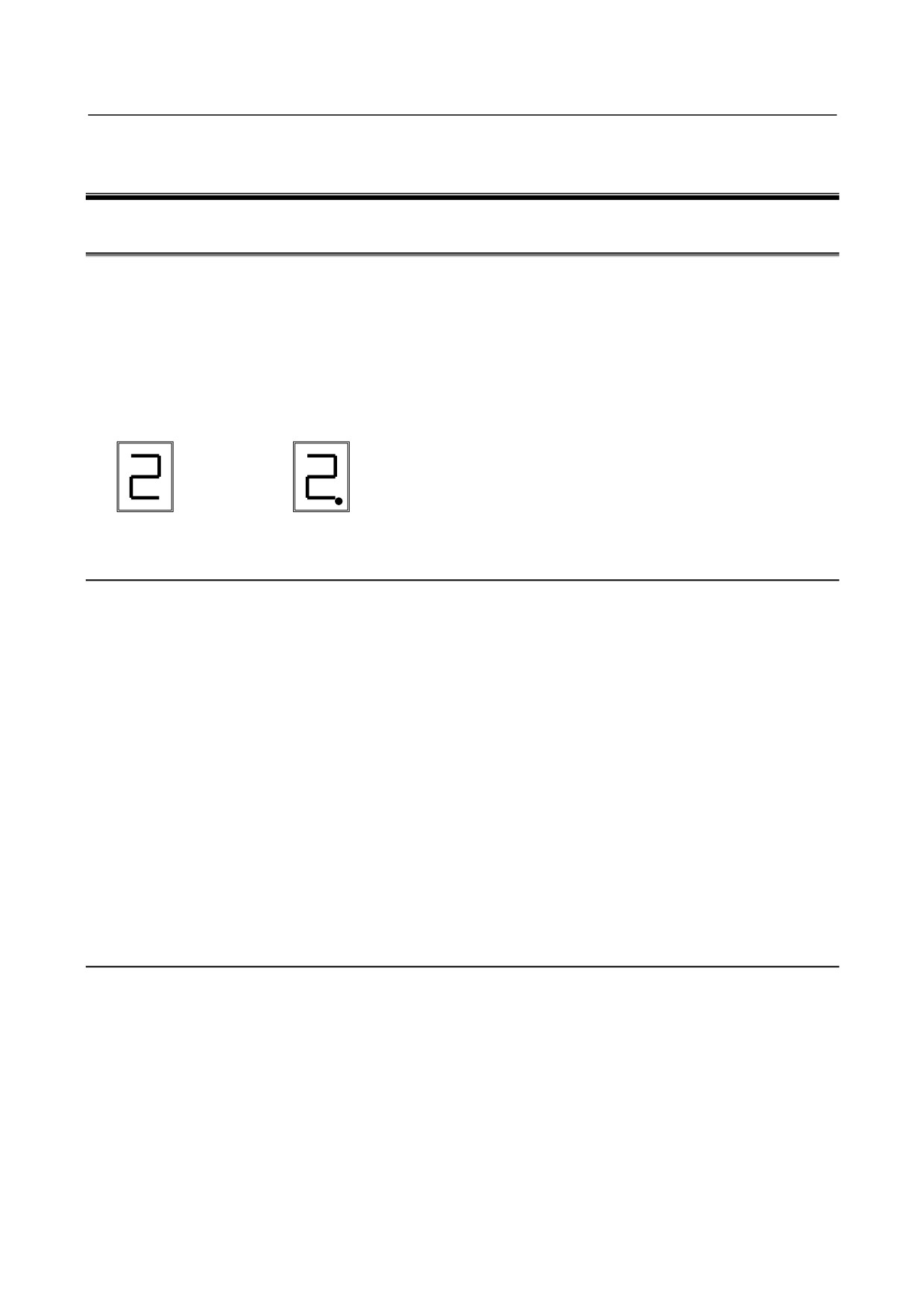
If an alarm occurs, in the STATUS display, the ALM LED lights red, and the one-digit 7-segment display
indicates an alarm code or warning code.
The meaning of each warning code is the same as that of the corresponding alarm code. If a warning
code is displayed, an alarm condition will occur in a certain period of time. The Power Supply remains
operable while the warning code stays displayed.
Example of an alarm
Example of a warning
code display
code display
3.1.1
No LED Display (αiPS, αiPSR)
(1) Meaning
The 200-V control power (CX1A) is not supplied.
Alternatively, the 24-VDC power is short-circuited.
(2) Cause and troubleshooting
(a) Check whether the circuit breaker for the control power supply is off.
When a lightning surge absorber is connected immediately following the circuit breaker, check
whether the lightning surge absorber is short-circuited by lightning. If the lightning surge
absorber is short-circuited, replace it.
(b) Disconnect the cable from the connector CX1A and turn the control power on. If "-" is displayed,
the 24-V power to a Servo Amplifier or Spindle Amplifier may be short-circuited.
→ Detect the amplifier which causes the power to be short-circuited by sequentially
connecting the cable from the Power Supply and replace it.
(c) Disconnect the cable from the connector CX4 and turn the control power on. If "-" is displayed,
the external 24-V power may be connected to pin 3 of CX4 incorrectly.
→ Correct the connection.
3.1.2
Alarm Code 1 (αiPS)
For the αiPS-5.5 to -15 and 11HV to 18HV
(1) Meaning
The main circuit power module (IPM) has detected an abnormal condition.
(2) Cause and troubleshooting
(a) Control supply voltage decrease of the power module (IPM)
→ Replace the power unit.
(b) Input supply voltage imbalance
→ Check the input power supply specification.
(c) The specification of the AC reactor does not match the PSM in use.
→ Check the PSM and the specification of the AC reactor.
- 64 -
3.TROUBLESHOOTING AND
B-65285EN/04
TROUBLESHOOTING
ACTION
(d) IPM failure
→ Replace the IPM.
For the αiPS15 to -55 and 30HV to 100HV
(1) Meaning
Overcurrent flowed into the input of the main circuit.
(2) Cause and troubleshooting
(a) Input supply voltage imbalance
→ Check the input power supply specification.
(b) The specification of the AC reactor does not match the PSM in use.
→ Check the PSM and the specification of the AC reactor.
(c) IGBT defective
→ Replace IGBT.
3.1.3
Alarm Code 2 (αiPS, αiPSR)
(1) Meaning
A cooling fan for the control circuit has stopped.
With the A06B-6140-HXXX or A06B-6150-HXXX (an upgrade version of PS), this alarm is also
issued when a unit stirring fan has stopped.
(2) Cause and troubleshooting
(a) Cooling fan broken
Check whether the cooling fan rotates normally.
→ Replace it.
(b) Internal stirring fan broken (only with an upgrade version of PS)
→ Replace it.
3.1.4
Alarm Code 3 (αiPS)
(1) Meaning
The temperature of the main circuit heat sink has risen abnormally.
(2) Cause and troubleshooting
(a) Cooling fan for the main circuit broken
Check whether the cooling fan for the main circuit rotates normally.
→ Replace it.
(b) Dust accumulation
→ Clean the cooling system with a vacuum cleaner or the factory air blower.
(c) Overload
→ Examine the operating conditions.
(d) Poor installation of the control printed-circuit board
→ Be sure to push the faceplate as far as it will go. (This alarm may be displayed if one of the
connectors for connection between the control printed-circuit board and power
printed-circuit board is detached.)
3.1.5
Alarm Code 4 (αiPS, αiPSR)
(1) Meaning
In the main circuit, the DC voltage (DC link) has dropped.
(2) Cause and troubleshooting
(a) A small power dip has occurred.
→ Check the power supply.
- 65 -
3.TROUBLESHOOTING AND
ACTION
TROUBLESHOOTING
B-65285EN/04
(b) Low input power supply voltage
→ Check the power supply specification.
(c) The main circuit power supply may have been switched off with an emergency stop state
released.
→ Check the sequence.
3.1.6
Alarm Code 5 (αiPS, αiPSR)
(1) Meaning
The main circuit capacitor was not recharged within the specified time.
(2) Cause and troubleshooting
(a) Too many Servo Amplifier and/or Spindle Amplifier units are connected.
→ Check the specification of the PSM.
(b) The DC link is short-circuited.
→ Check the connection.
(c) The recharge current limiting resistor is defective.
→ Replace the distributing board.
3.1.7
Alarm Code 6 (αiPS, αiPSR)
(1) Meaning
The control power supply voltage decrease.
The 24-V power supply is abnormal in the Power Supply. (Internal fuse blown)
(2) Cause and troubleshooting
(a) Input voltage decrease
→ Check the power supply.
(b) Power Supply broken
→ If this alarm is issued just by turning the control power on, replace the Power Supply.
3.1.8
Alarm Code 7 (αiPS, αiPSR)
(1) Meaning
In the main circuit, the DC voltage at the DC link is abnormally high.
(2) Cause and troubleshooting
(a) Excessive regenerated power
The PSM does not have a sufficient capacity.
→ Check the specification of the PSM.
(b) The output impedance of the AC power source is too high.
→ Check the power source output impedance.
(Normal if the voltage variation at maximum output time is within 7%)
(c) The main circuit power supply may have been switched off with an emergency stop state
released.
→ Check the sequence.
3.1.9
Alarm Code 8 (αiPSR)
(1) Meaning
There is excessive short-term regenerative power.
(2) Cause and troubleshooting
(a) Insufficient regenerative resistance
→ Review the specification of the regenerative resistance.
- 66 -

3.TROUBLESHOOTING AND
B-65285EN/04
TROUBLESHOOTING
ACTION
(b) Regenerative circuit failure
→ The regenerative circuit is abnormal. Replace the PSMR.
3.1.10 Alarm Code A (αiPS)
(1) Meaning
A cooling fan of external cooling fin has stopped.
With the A06B-6110-HXXX or A06B-6120-HXXX, this alarm is also issued when a unit stirring fan
has stopped.
(2) Cause and troubleshooting
(a) Cooling fan for the radiator cooling fin broken
Check whether the cooling fan for the radiator cooling fin rotates normally.
→ Replace it.
(b) Unit stirring fan broken (A06B-6110-HXXX,A06B-6120-HXXX のみ)
Check whether the unit stirring fan rotates normally.
→ Replace it.
(c) Poor installation of the control printed-circuit board
→ Be sure to install the control printed-circuit board.
(This alarm may be issued if one of the connectors for connection between the control
printed-circuit board and power printed-circuit board become loose.)
(d) Poor installation of the control printed-circuit board
→ Be sure to push the faceplate as far as it will go. (This alarm may be displayed if one of the
connectors for connection between the control printed-circuit board
and
power
printed-circuit board is detached.)
3.1.11 Alarm Code E (αiPS, αiPSR)
(1) Meaning
The input power supply is abnormal (open phase).
(2) Cause and troubleshooting
(a) The input power supply has an open phase.
Check the power supply voltage.
→ If there is no problem with the power supply voltage, check the connections.
3.1.12 Alarm Code H (αiPSR)
(1) Meaning
The temperature of the regenerative resistor has arisen abnormally.
(2) Cause and troubleshooting
(a) Regenerative resistance not detected
→ Check the wiring for the regenerative resistance.
(b) Insufficient regenerative resistance
→ Review the specification for the regenerative resistance.
(c) Excessive regenerative power
→ Reduce the frequency at which acceleration/ deceleration occurs.
(d) Regenerative resistor cooling fan stopped
→ Check to see if the regenerative resistor cooling fan has stopped.
3.1.13 Alarm Code P (αiPS, αiPSR)
(1) Meaning
Communication error between amplifiers
- 67 -
3.TROUBLESHOOTING AND
ACTION
TROUBLESHOOTING
B-65285EN/04
(2) Cause and troubleshooting
(a) Check the connector and cable (CXA2A).
(b) Replace the Power Supply (control printed-circuit board).
3.2
SERVO AMPLIFIER
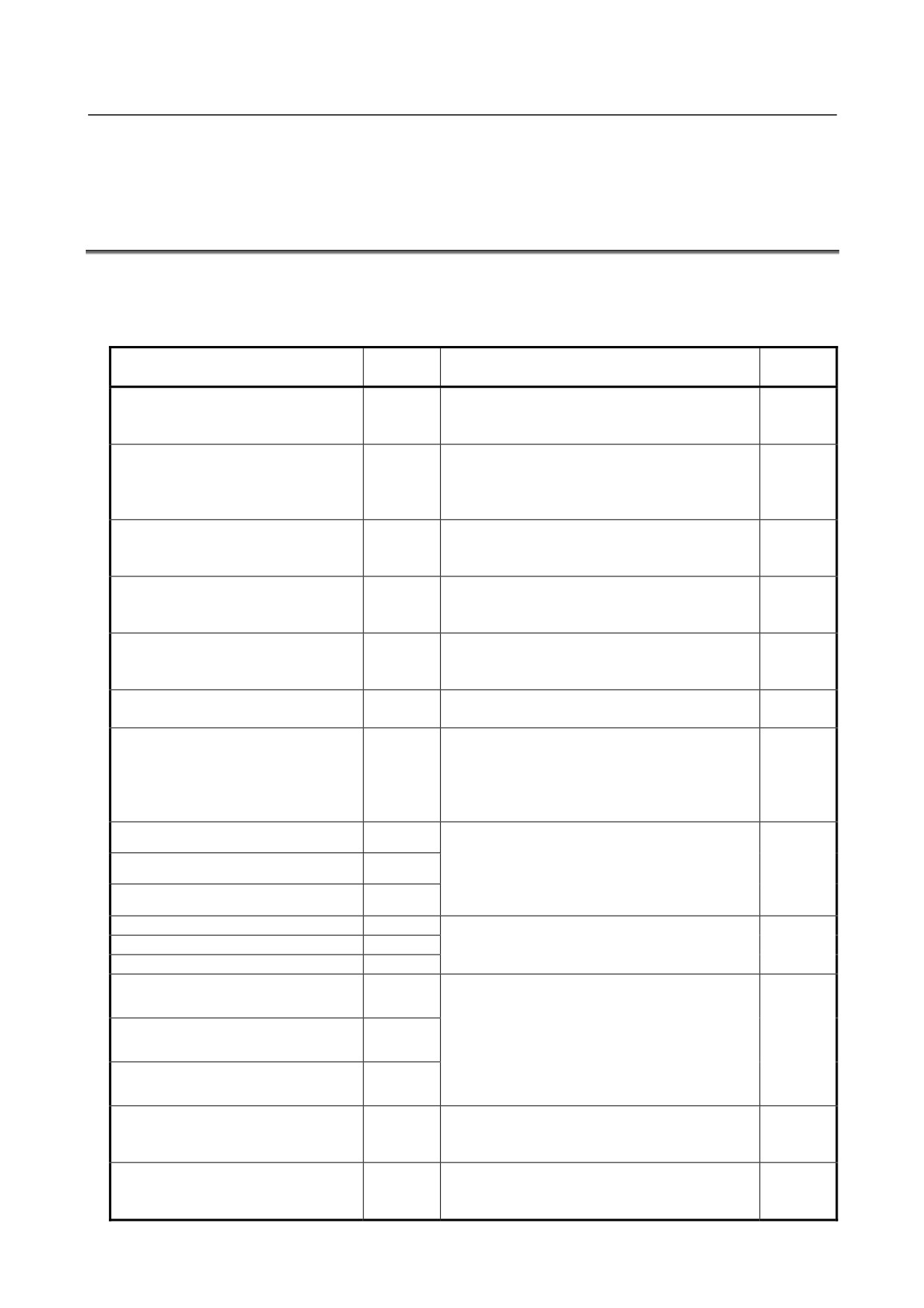
The following table lists alarms related to the Servo Amplifier.
See this table while comparing the CNC alarm codes presented in Chapter 2, "Alarm Numbers and Brief
Description" with the LED displays of the Servo Amplifier.
LED
Alarm
Major cause
Reference
display
- Fan not running.
Inverter: internal cooling fan stopped
1
- Fan motor connector or cable defective
3.2.1
- Servo Amplifier failure
- The 24 V control power supply output from the
Inverter: control power supply
Power Supply is low.
2
3.2.2
undervoltage
- Connector/cable (CXA2A/B) defective
- Servo Amplifier failure
- Low input voltage
Inverter: DC link undervoltage
5
- DC link short-bar poor connection
3.2.3
- Servo Amplifier failure
- The motor is being used under a harsh condition.
Inverter: overheat
6
- The ambient temperature is high.
3.2.4
- Servo Amplifier failure
- Fan not running.
Inverter: cooling fan stopped of the
F
- Fan motor connector or cable defective
3.2.5
radiator
- Servo Amplifier failure
Communication error between
- Connector/cable (CXA2A/B) defective
P
3.2.6
amplifiers
- Servo Amplifier failure
- Short-circuit between power lead phases or
ground fault in them
Inverter: DC link current alarm (L axis)
8
- Short-circuit between motor winding phases or
3.2.7
ground fault in them
- Servo Amplifier failure
- Short-circuit between power lead phases or
Inverter: IPM alarm (L axis)
8.
ground fault in them
Inverter: IPM alarm (M axis)
9.
- Short-circuit between motor winding phases or
3.2.8
ground fault in them
Inverter: IPM alarm (N axis)
A.
- Servo Amplifier failure
Inverter: IPM alarm (OH) (L axis)
8.
- The motor is being used under a harsh condition.
Inverter: IPM alarm (OH) (M axis)
9.
- The ambient temperature is high.
3.2.9
Inverter: IPM alarm (OH) (N axis)
A.
- Servo Amplifier failure
- Short-circuit between power lead phases or
Inverter: motor current alarm (L axis)
b
ground fault in them
- Short-circuit between motor winding phases or
Inverter: motor current alarm (M axis)
c
ground fault in them
3.2.10
- Incorrect motor ID setting
- Servo Amplifier failure
Inverter: motor current alarm (N axis)
d
- Motor failure
- Connector or cable (JF*) failure
Inverter: abnormal control power
Blinking -
- Motor failure
3.2.11
supply
- Servo Amplifier failure
- Connector or cable (COP10B) failure
Inverter: FSSB communication error
U
- Servo Amplifier failure
3.2.12
(COP10B)
- CNC failure
- 68 -
3.TROUBLESHOOTING AND
B-65285EN/04
TROUBLESHOOTING
ACTION
LED
Alarm
Major cause
Reference
display
Inverter: FSSB communication error
- Connector or cable (COP10A) failure
L
3.2.13
(COP10A)
- Servo Amplifier failure
3.2.1
Alarm Code 1
(1) Meaning
Inverter: internal cooling fan stopped
(2) Cause and troubleshooting
(a) Check whether there is any foreign material in the fan.
(b) Be sure to push the faceplate (control printed-circuit board) as far as it will go.
(c) Check that the fan connector is attached correctly.
(d) Replace the fan.
(e) Replace the Servo Amplifier.
3.2.2
Alarm Code 2
(1) Meaning
Inverter: control power supply undervoltage
(2) Cause and troubleshooting
(a) Check the three-phase input voltage of the amplifier (the voltage shall not be lower than 85% of
the rated input voltage).
(b) Check the 24 V power supply voltage output from the Power Supply (the voltage shall normally
not lower than 22.8 V).
(c) Check the connector and cable (CXA2A/B).
(d) Replace the Servo Amplifier.
3.2.3
Alarm Code 5
(1) Meaning
Inverter: DC link undervoltage
(2) Cause and troubleshooting
(a) Check that the screws for the DC link connection cable (bar) are tight.
(b) If a DC link low voltage alarm condition occurs in more than one module, see Subsection 3.1.4,
"Alarm code 4" for explanations about how to troubleshoot the Power Supply.
(c) If a DC link low voltage alarm condition occurs in one Servo Amplifier only, be sure to push the
faceplate (control printed-circuit board) of that Servo Amplifier as far as it will go.
(d) Replace the Servo Amplifier in which this alarm has occurred.
3.2.4
Alarm Code 6
(1) Meaning
Inverter: overheat
(2) Cause and troubleshooting
(a) Check that the motor is being used at or below its continuous rating.
(b) Check that the cooling capacity of the cabinet is sufficient (inspect the fans and filters).
(c) Check that the ambient temperature is not too high.
(d) Be sure to push the faceplate (control printed-circuit board) as far as it will go.
(e) Replace the Servo Amplifier.
- 69 -
3.TROUBLESHOOTING AND
ACTION
TROUBLESHOOTING
B-65285EN/04
3.2.5
Alarm Code F
(1) Meaning
Inverter: cooling fan stopped of the radiator
(2) Cause and troubleshooting
(a) Check whether there is any foreign material in the fan.
(b) Be sure to push the faceplate (control printed-circuit board) as far as it will go.
(c) Check that the fan connector is attached correctly.
(d) Replace the fan.
(e) Replace the Servo Amplifier.
3.2.6
Alarm Code P
(1) Meaning
Communication error between amplifiers
(2) Cause and troubleshooting
(a) Check the connector and cable (CXA2A/B).
(b) Replace the control printed-circuit board.
(c) Replace the Servo Amplifier.
3.2.7
Alarm Code 8
(1) Meaning
Inverter: DC link current alarm
(2) Cause and troubleshooting
(a) Disconnect the motor power leads from the Servo Amplifier, and release the Servo Amplifier
from an emergency stop condition.
<1> If no abnormal DC link current alarm condition has occurred
→ Go to (b).
<2> If an abnormal DC link current alarm condition has occurred
→ Replace the Servo
Amplifier.
(b) Disconnect the motor power leads from the Servo Amplifier, and check the insulation between
PE and the motor power lead U, V, or W.
<1> If the insulation is deteriorated
→ Go to (c).
<2> If the insulation is normal
→ Replace the Servo Amplifier.
(c) Disconnect the motor from its power leads, and check whether the insulation of the motor or
power leads is deteriorated.
<1> If the insulation of the motor is deteriorated
→ Replace the motor.
<2> If the insulation of any power lead is deteriorated → Replace the power lead.
3.2.8
Alarm Codes 8., 9., and A.
(1) Meaning
Inverter: IPM alarm
(2) Cause and troubleshooting
(a) Be sure to push the faceplate (control printed-circuit board) as far as it will go.
(b) Disconnect the motor power leads from the Servo Amplifier, and release the Servo Amplifier
from an emergency stop condition.
<1> If no IPM alarm condition has occurred
→ Go to (b).
<2> If an IPM alarm condition has occurred
→ Replace the Servo Amplifier.
(c) Disconnect the motor power leads from the Servo Amplifier, and check the insulation between
PE and the motor power lead U, V, or W.
<1> If the insulation is deteriorated
→ Go to (c).
<2> If the insulation is normal
→ Replace the Servo Amplifier.
- 70 -
3.TROUBLESHOOTING AND
B-65285EN/04
TROUBLESHOOTING
ACTION
(d) Disconnect the motor from its power leads, and check whether the insulation of the motor or
power leads is deteriorated.
<1> If the insulation of the motor is deteriorated
→ Replace the motor.
<2> If the insulation of any power lead is deteriorated → Replace the power lead.
3.2.9
Alarm Codes 8., 9., and A.
(1) Meaning
Inverter: IPM alarm (OH)
(2) Cause and troubleshooting
(a) Be sure to push the faceplate (control printed-circuit board) as far as it will go.
(b) Check that the heat sink cooling fan is running.
(c) Check that the motor is being used at or below its continuous rating.
(d) Check that the cooling capacity of the cabinet is sufficient (inspect the fans and filters).
(e) Check that the ambient temperature is not too high.
(f) Replace the Servo Amplifier.
3.2.10 Alarm Codes b, c, and d
(1)
Meaning
Inverter: DC link current alarm
(2)
Cause and troubleshooting
(a) Checking the servo parameters
Referring to "FANUC AC SERVO MOTOR αi series Parameter Manual (B-65270EN)," check
whether the following parameters have default values.
Series 15i
No.1809
No.1852
No.1853
Series 16i, 18i, 20i, 21i, 0i
No.2004
No.2040
No.2041
Power Mate i
Alternatively, if an abnormal motor current alarm condition occurs only on rapid
acceleration/deceleration, it is likely that the motor is being used under too harsh a condition.
Increase the acceleration/deceleration time constant, and see what will occur.
(b) Be sure to push the faceplate (control printed-circuit board) as far as it will go.
(c) Disconnect the motor power leads from the Servo Amplifier, and release the Servo Amplifier
from an emergency stop condition.
<1> If no abnormal motor current occurs
→ Go to (c).
<2> If an abnormal motor current occurs
→ Replace the Servo Amplifier.
(d) Disconnect the motor power leads from the Servo Amplifier, and check the insulation between
PE and the motor power lead U, V, or W.
<1> If the insulation is deteriorated
→ Go to (d).
<2> If the insulation is normal
→ Replace the Servo Amplifier.
(e) Disconnect the motor from its power leads, and check whether the insulation of the motor or
power leads is deteriorated.
<1> If the insulation of the motor is deteriorated
→ Replace the motor.
<2> If the insulation of any power lead is deteriorated
→ Replace the power lead.
3.2.11 Alarm Code "-" Blinking
(1) Meaning
Inverter: abnormal control power supply
(2) Cause and troubleshooting
(a) Disconnect the feedback cable (JF*) from the Servo Amplifier, and then switch on the power.
<1> If blinking continues
→ Replace the Servo Amplifier.
<2> If blinking stops
→ Go to (b).
- 71 -