FANUC AC SERVO MOTOR ai series, AC SPINDLE MOTOR ai series, SERVO AMPLIFIER ai series. MAINTENANCE MANUAL - page 4
3.TROUBLESHOOTING AND
ACTION
TROUBLESHOOTING
B-65285EN/04
(b) Disconnect the feedback cable (JF*) from the Pulsecoder, and then switch on the power. (Keep
the cable on the Servo Amplifier side connected.)
<1> If blinking continues
→ Replace the cable.
<2> If blinking stops
→ Replace the motor.
3.2.12 Alarm Code U
(1) Meaning
Inverter: FSSB communication error (COP10B) (NOTE)
(2) Cause and troubleshooting
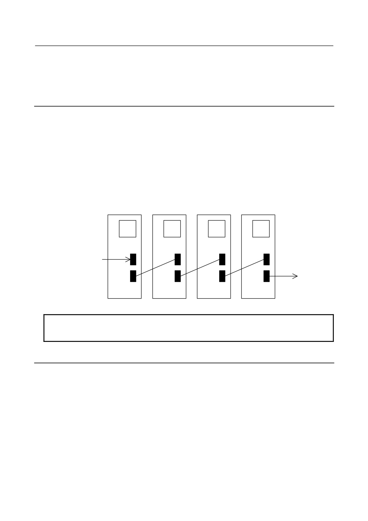
(a) Replace the Servo Amplifier optical cable (COP10B) that is nearest to the CNC on which "U" is
displayed (in Fig. 3.2.12, the cable between UNIT2 and UNIT3).
(b) Replace the Servo Amplifier that is nearest to the CNC on which "U" is displayed (in Fig. 3.2.12,
UNIT3).
(c) Replace the COP10B-side Servo Amplifier that is nearest to the CNC on which "U" is displayed
(in Fig. 3.2.12, UNIT2).
(d) Replace the servo card in the CNC.
UNIT1
UNIT2
UNIT3
UNIT4
L
L
U
U
COP10B
COP10B
COP10B
COP10B
Master side
(CNC side)
Slave side
COP10A
COP10A
COP10A
COP10A
Fig. 3.2.12
NOTE
When the CNC power is turned on, "U" blinks momentarily, and then "-" steadily
lights. This is not a failure, though.
3.2.13 Alarm Code L
(1) Meaning
Inverter: FSSB communication error (COP10A)
(2) Cause and troubleshooting
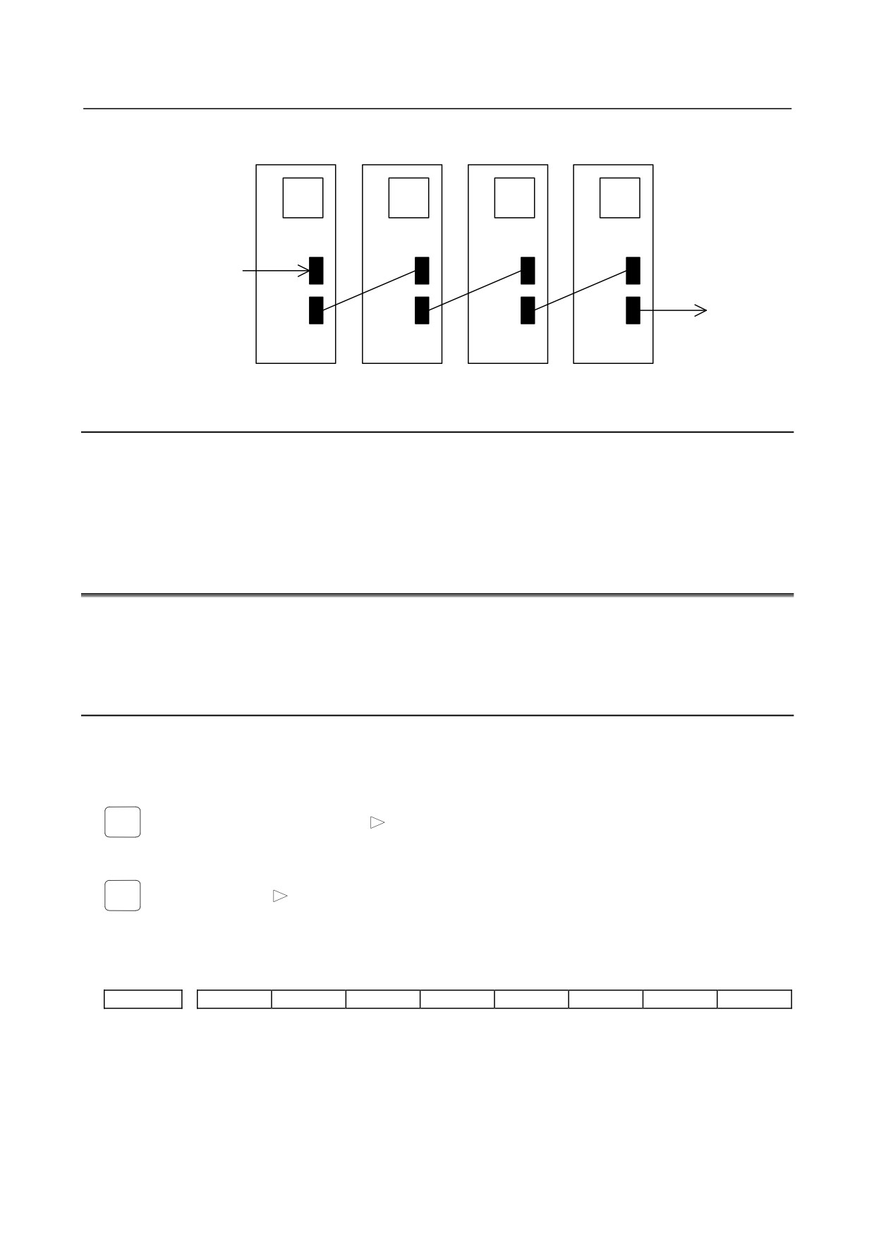
(a) Replace the Servo Amplifier optical cable (COP10A) that is farthest to the CNC on which "L" is
displayed (in Fig. 3.2.13, the cable between UNIT2 and UNIT3).
(b) Replace the Servo Amplifier that is farthest to the CNC on which "L" is displayed (in Fig. 3.2.13,
UNIT2).
(c) Replace the COP10A-side Servo Amplifier that is farthest to the CNC on which "L" is displayed
(in Fig. 3.2.13, UNIT3).
- 72 -
3.TROUBLESHOOTING AND
B-65285EN/04
TROUBLESHOOTING
ACTION
UNIT1
UNIT2
UNIT3
UNIT4
L
L
U
U
COP10B
COP10B
COP10B
COP10B
Master side
(CNC side)
Slave side
COP10A
COP10A
COP10A
COP10A
Fig. 3.2.13
3.2.14 DB Relay Error (CNC Message "Alarm SV0654")
(1) Meaning
DB relay error
(2) Cause and troubleshooting
(a) Check whether the power lead is short-circuited.
(b) Replace the Servo Amplifier.
3.3
SERVO SOFTWARE
If a servo alarm is issued, an alarm message is output, and details of the alarm are also displayed on the
servo adjustment screen or the diagnosis screen. Using the alarm identification table given in this section,
determine the alarm, and take a proper action.
3.3.1
Servo Adjustment Screen
The following procedure can be used to display the servo adjustment screen.
(The DPL/MDI of the Power Mate has no servo adjustment screen.)
z
Series 15i
SYSTEM
→ [CHAPTER] → [SERVO] → [
] → [SERVO ALARM]
z
Series 16i, 18i, 20i, 21i, 0i
SYSTEM
→ [SYSTEM] → [
] → [SV-PRM] → [SV-TUN]
If the servo setting screen does not appear, specify the following parameter, then switch the CNC off and on
again.
#7
#6
#5
#4
#3
#2
#1
#0
3111
SVS
SVS (#0)=1 (to display the servo setting screen)
- 73 -
3.TROUBLESHOOTING AND
ACTION
TROUBLESHOOTING
B-65285EN/04
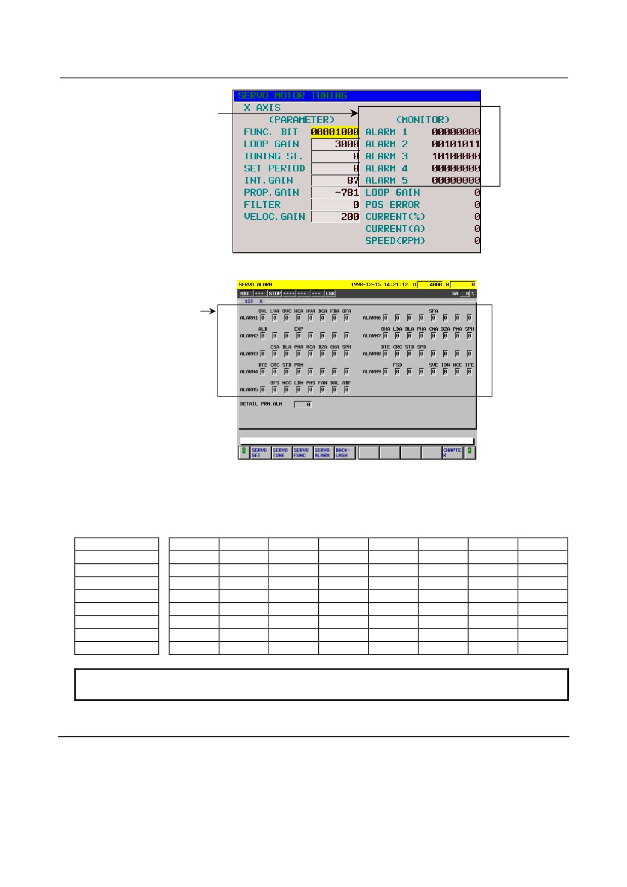
Alarm detail
information
<1>
<2>
<3>
<4>
<5>
Fig. 3.3.1(a) Servo adjustment screen
Alarm detail
information
<1>
<6>
<2>
<7>
<3>
<8>
<4>
<9>
<5>
Fig. 3.3.1(b) Series 15i servo alarm screen
The table below indicates the names of the alarm bits.
Table 3.3.1 List of alarm bit names
#7
#6
#5
#4
#3
#2
#1
#0
<1> Alarm 1
OVL
LVA
OVC
HCA
HVA
DCA
FBA
OFA
<2> Alarm 2
ALD
EXP
<3> Alarm 3
CSA
BLA
PHA
RCA
BZA
CKA
SPH
<4> Alarm 4
DTE
CRC
STB
PRM
<5> Alarm 5
OFS
MCC
LDM
PMS
FAN
DAL
ABF
<6> Alarm 6
SFA
<7> Alarm 7
OHA
LDA
BLA
PHA
CMA
BZA
PMA
SPH
<8> Alarm 8
DTE
CRC
STB
SPD
<9> Alarm 9
FSD
SVE
IDW
NCE
IFE
NOTE
The empty fields do not represent alarm codes.
3.3.2
Diagnosis Screen
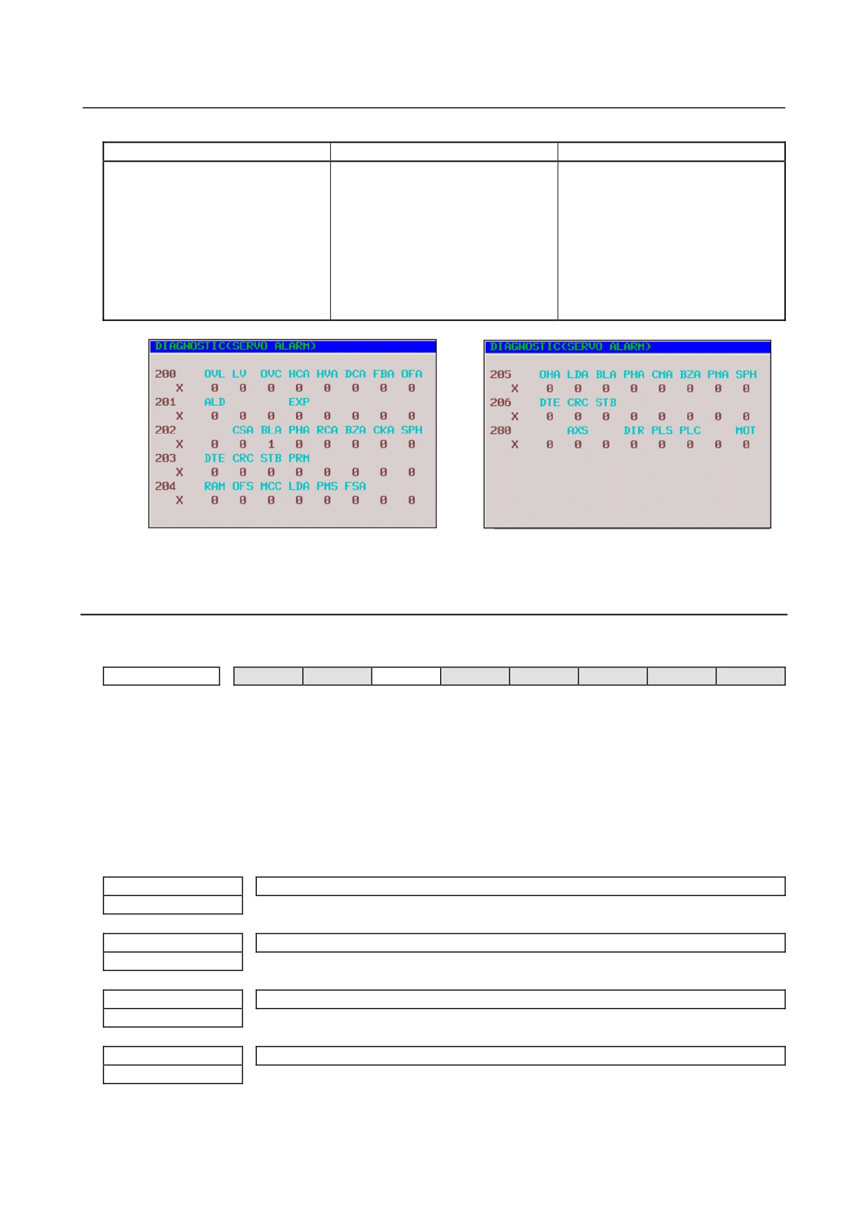
The alarm items of the servo adjustment screen correspond to the diagnosis screen numbers indicated in the
table below.
- 74 -
3.TROUBLESHOOTING AND
B-65285EN/04
TROUBLESHOOTING
ACTION
Table 3.3.2
Correspondence between the servo adjustment screen and diagnosis screen
Alarm No.
Series 15i
Series 16i, 18i, 21i, 0i
<1> Alarm 1
No 3014 + 20(X-1)
No
200
<2> Alarm 2
3015 + 20(X-1)
201
<3> Alarm 3
3016 + 20(X-1)
202
<4> Alarm 4
3017 + 20(X-1)
203
<5> Alarm 5
⎯⎯⎯⎯⎯
204
<6> Alarm 6
⎯⎯⎯⎯⎯
⎯⎯
<7> Alarm 7
⎯⎯⎯⎯⎯
205
<8> Alarm 8
⎯⎯⎯⎯⎯
206
<9> Alarm 9
⎯⎯⎯⎯⎯
⎯⎯
<1>
<7>
<2>
<8>
<3>
<4>
<5>
Fig. 3.3.2 Diagnosis screen
3.3.3
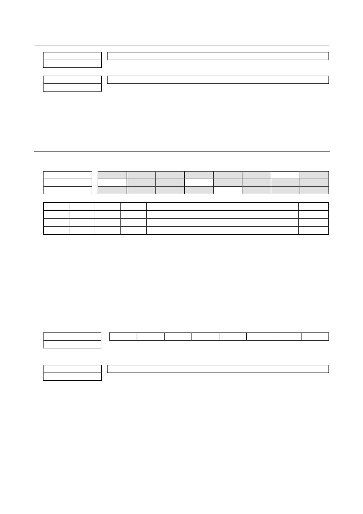
Overload Alarm (Soft Thermal, OVC)
(Alarm identification method)
#7
#6
#5
#4
#3
#2
#1
#0
<1> Alarm 1
OVL
LVA
OVC
HCA
HVA
DCA
FBA
OFA
(Action)
(1) Make sure that the motor is not vibrating.
⇒ If a motor vibrates, the current flowing in it becomes more than necessary, resulting in an alarm.
(2) Make sure that the power lead to the motor is connected correctly.
⇒ If the connection is incorrect, an abnormal current flows in the motor, resulting in an alarm.
(3) Make sure that the following parameters are set correctly.
⇒ An overload alarm is issued based on the result of calculation of these parameters. Be sure to set
them to the standard values. For details of the standard values, refer to the FANUC AC SERVO
MOTOR αi series Parameter Manual (B-65270EN).
No. 1877 (FS15i)
Overload protection coefficient (OVC1)
No. 2062 (FS16i)
No. 1878 (FS15i)
Overload protection coefficient (OVC2)
No. 2063 (FS16i)
No. 1893 (FS15i)
Overload protection coefficient (OVCLMT)
No. 2065 (FS16i)
No. 1785 (FS15i)
Overload protection coefficient (OVC21)
No. 2162 (FS16i)
- 75 -
3.TROUBLESHOOTING AND
ACTION
TROUBLESHOOTING
B-65285EN/04
No. 1786 (FS15i)
Overload protection coefficient (OVC22)
No. 2163 (FS16i)
No. 1787 (FS15i)
Overload protection coefficient (OVCLMT2)
No. 2165 (FS16i)
Measure the actual current values (IR, IS) using the SERVO GUIDE, compare the values with overload
duty curves in the Servo Motor Descriptions (B-65262EN), and check whether the load on the machine is
too large compared with the motor capacity. If the actual current is high on acceleration/deceleration, it is
likely that the time constant is too small.
3.3.4
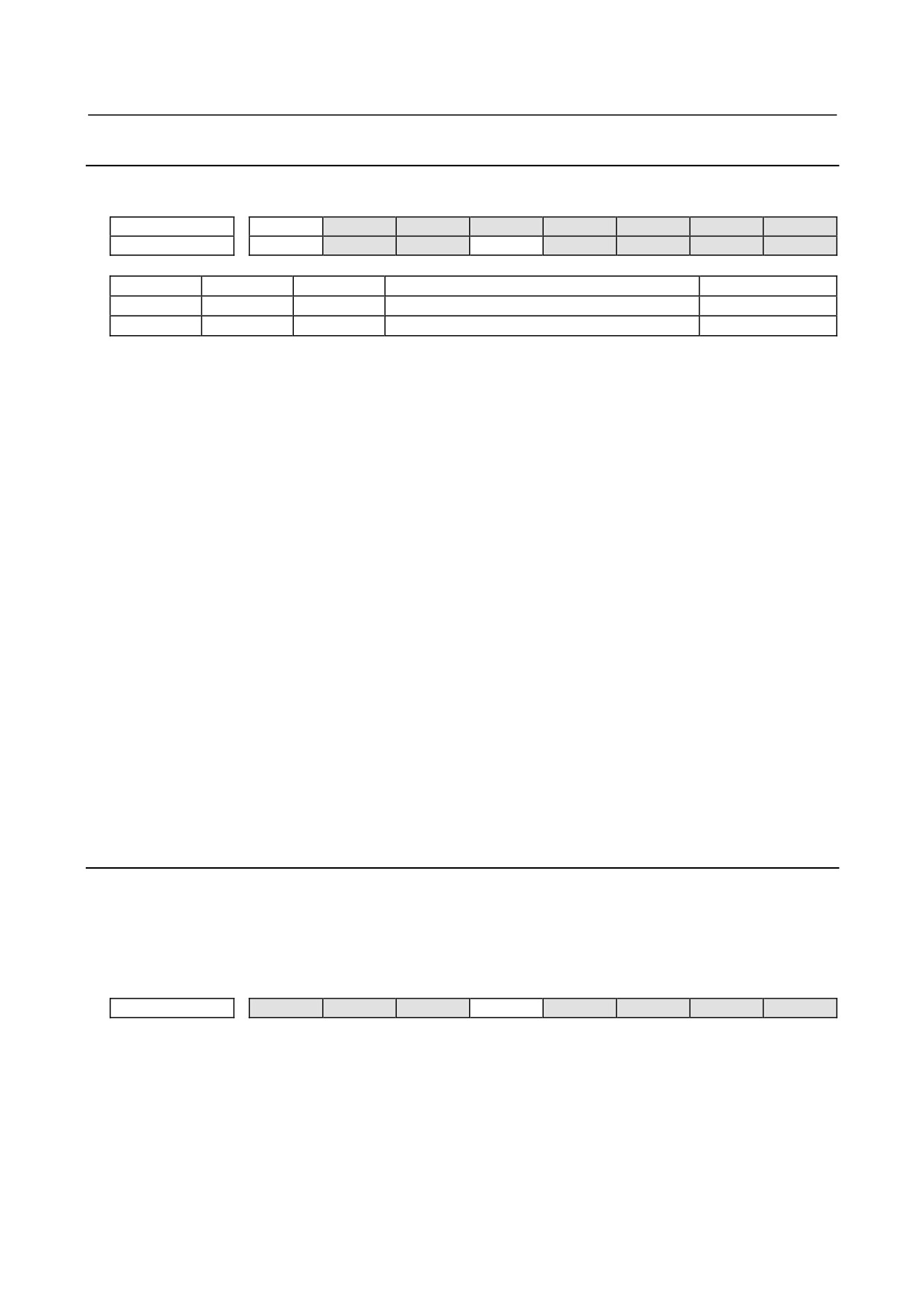
Feedback Disconnected Alarm
(Alarm identification method)
#7
#6
#5
#4
#3
#2
#1
#0
<1> Alarm 1
OVL
LVA
OVC
HCA
HVA
DCA
FBA
OFA
<2> Alarm 2
ALD
EXP
<6> Alarm 6
SFA
FBA
ALD
EXP
SFA
Alarm description
Action
1
1
1
0
Hard disconnection (separate phase A/B)
1
1
0
0
0
Soft disconnection (closed loop)
2
1
0
0
1
Soft disconnection (αi Pulsecoder)
3
(Action)
Action 1: This alarm is issued when a separate phase A/B scale is used. Check if the phase A/B
detector is connected correctly.
Action 2: This alarm is issued when the position feedback pulse variation is small relative to the
velocity feedback pulse variation. This means that this alarm is not issued when a semi-full
is used. Check if the separate detector outputs position feedback pulses correctly. If
position feedback pulses are output correctly, it is considered that the motor alone is
rotating in the reverse direction at the start of machine operation because of a large
backlash between the motor position and scale position.
#7
#6
#5
#4
#3
#2
#1
#0
No. 1808 (FS15i)
TGAL
No. 2003 (FS16i)
TGAL (#1) 1: Uses the parameter for the soft disconnection alarm detection level.
No. 1892 (FS15i)
Soft disconnection alarm level
No. 2064 (FS16i)
Standard setting 4: Alarm issued for a 1/8 rotation of the motor.
Increase this value.
Action 3: This alarm is issued when synchronization between the absolute position data sent from the
built-in Pulsecoder and phase data is lost. Turn off the power to the CNC, then detach the
Pulsecoder cable then attach it again. If this alarm is still issued, replace the Pulsecoder.
- 76 -
3.TROUBLESHOOTING AND
B-65285EN/04
TROUBLESHOOTING
ACTION
3.3.5
Overheat Alarm
(Alarm identification method)
#7
#6
#5
#4
#3
#2
#1
#0
<1> Alarm 1
OVL
LVA
OVC
HCA
HVA
DCA
FBA
OFA
<2> Alarm 2
ALD
EXP
OVL
ALD
EXP
Alarm description
Action
1
1
0
Motor overheat
1
1
0
0
Amplifier overheat
1
(Action)
(1) Motor overheat
First, check whether the motor temperature is high immediately after the alarm is issued. If the alarm is
issued when the motor temperature is not high, the temperature detection circuit may be abnormal.
Contact your FANUC service staff.
When the motor temperature is high immediately after the alarm is issued, check the following items:
(a) Check the cooling state of the motor.
<1> If the cooling state is abnormal, for example, when the cooling fan stops, check the power
specification (voltage, phase sequence, and so on) of the cooling fan. If there is no problem
with the power specification, replace the fan unit.
<2> When a liquid-cooled motor is used, check the cooling system.
<3> When the motor ambient temperature is higher than the specified temperature, lower the
ambient temperature to satisfy the specification.
(b) Increase the time constant or stop time in the program to ease the cutting conditions.
Motor temperature information is displayed on the diagnosis screen.
Motor temperature: Diagnosis information No. 308 (Series 16i, 30i, and others), diagnosis
information No. 3520 (Series 15i)
Pulsecoder temperature: Diagnosis information No. 309 (Series 16i, 30i, and others), diagnosis
information No. 3521 (Series 15i)
If an overheat alarm is issued when the temperature is not high, contact your FANUC service
staff.
(2) Amplifier overheat
See the description about inverter overheat in Subsection 3.2.4.
3.3.6
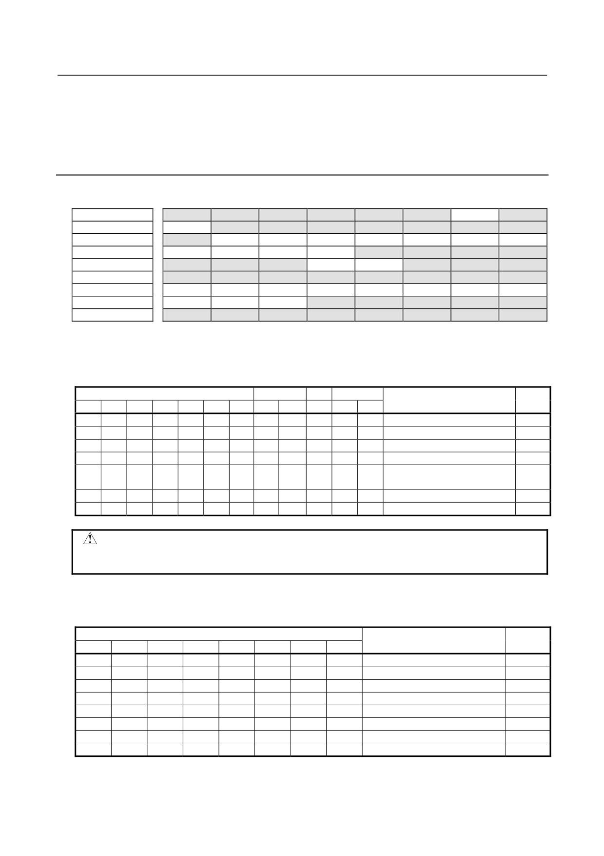
Invalid Servo Parameter Setting Alarm
The invalid servo parameter setting alarm is issued when a setting out of the specifiable range is specified,
or an overflow has occurred in an internal calculation. When an invalid parameter is detected on the servo
side, alarm 4 #4 (PRM) = 1 results.
(Alarm identification method)
#7
#6
#5
#4
#3
#2
#1
#0
<4> Alarm 4
DTE
CRC
STB
PRM
For details and action required when the invalid servo parameter setting alarm is issued on the servo side,
refer to the FANUC AC SERVO MOTOR αi series Parameter Manual (B-65270EN).
(Reference information)
Method of checking details of an invalid parameter detected on the servo side
(For Series 15i)
A number is indicated in the item "Details of invalid parameter" on the servo alarm screen (Fig.
3.3.1(b)).
- 77 -
3.TROUBLESHOOTING AND
ACTION
TROUBLESHOOTING
B-65285EN/04
(For Series 16i, 18i, 21i, 0i, and Power Mate i)
A number is indicated in No. 352 of the diagnosis screen.
Referring to "FANUC AC SERVO MOTOR αi series Parameter Manual (B-65270EN)" for details.
3.3.7
Alarms Related to Pulsecoder and Separate Serial Detector
(Bits for alarm identification)
#7
#6
#5
#4
#3
#2
#1
#0
<1> Alarm 1
OVL
LVA
OVC
HCA
HVA
DCA
FBA
OFA
<2> Alarm 2
ALD
EXP
<3> Alarm 3
CSA
BLA
PHA
RCA
BZA
CKA
SPH
<4> Alarm 4
DTE
CRC
STB
PRM
<5> Alarm 5
OFS
MCC
LDM
PMS
FAN
DAL
ABF
<6> Alarm 6
SFA
<7> Alarm 7
OHA
LDA
BLA
PHA
CMA
BZA
PMA
SPH
<8> Alarm 8
DTE
CRC
STB
SPD
<9> Alarm 9
FSD
SVE
IDW
NCE
IFE
(1) For a built-in Pulsecoder
An alarm is determined from the bits of alarms 1, 2, 3, and 5. The table below indicates the meaning of
each bit.
Alarm 3
Alarm 5
1
Alarm 2
Alarm description
Action
CSA
BLA
PHA
RCA
BZA
CKA
SPH
LDM
PMA
FBA
ALD
EXP
1
Soft phase alarm
2
1
Zero battery voltage
1
1
1
1
0
Count error alarm
2
1
Phase alarm
2
Battery voltage decrease
1
1
(warning)
1
Pulse error alarm
1
LED error alarm
CAUTION
An alarm for which no action number is given is considered to be caused by a
Pulsecoder failure. Replace the Pulsecoder.
(2) For a separate serial detector
An alarm is determined from the bits of alarm 7. The table below indicates the meaning of each bit.
Alarm 7
Alarm description
Action
OHA
LDA
BLA
PHA
CMA
BZA
PMA
SPH
1
Soft phase alarm
2
1
Pulse error alarm
1
Zero battery voltage
1
1
Count error alarm
2
1
Phase alarm
2
1
Battery voltage decrease (warning)
1
1
LED error alarm
1
Separate detector alarm
3
- 78 -
3.TROUBLESHOOTING AND
B-65285EN/04
TROUBLESHOOTING
ACTION
CAUTION
An alarm for which no action number is given is considered to be caused by a
detector failure. Replace the detector.
(Action)
Action 1: Battery-related alarms
Check if a battery is connected. When the power is turned on for the first time after a battery
is connected, the zero battery voltage alarm is issued. In such a case, turn off the power,
then turn on the power again. If the alarm is still issued, check the battery voltage. If the
battery voltage decrease alarm is issued, check the voltage, and replace the battery as
required.
Action 2: Alarms that may be issued for noise
If an alarm is issued intermittently or after emergency stop cancellation, noise is probably
the cause. So, provide noise protection. If the same alarm is still issued after noise
protection is provided, replace the detector.
Action 3: Alarm condition detected by the separate detector
If the separate detector detects an alarm condition, contact the manufacturer of the detector
for information on troubleshooting.
(3) Alarms related to serial communication
An alarm is determined from the bits of alarms 4 and 8.
Alarm 4
Alarm 8
Alarm description
DTE
CRC
STB
DTE
CRC
STB
1
1
Serial Pulsecoder communication alarm
1
1
1
Separate serial Pulsecoder communication alarm
1
Action: Serial communication is not performed correctly. Check if the cable is connected correctly
and is not broken. If CRC or STB is issued, noise may be the cause. So, provide noise
protection. If CRC or STB is always issued after the power is turned on, the Pulsecoder or
amplifier control board or the pulse module may be faulty.
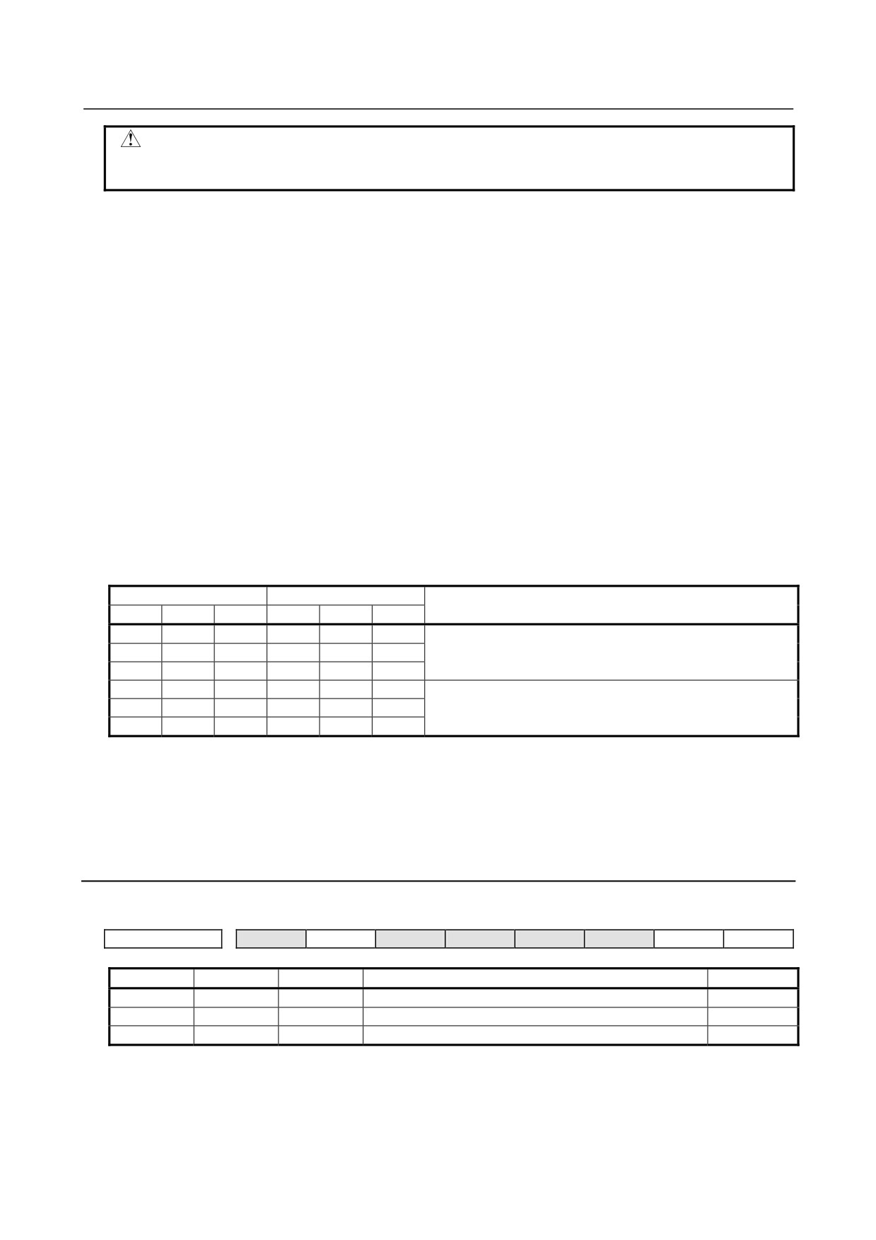
3.3.8
Other Alarms
(Alarm identification method)
#7
#6
#5
#4
#3
#2
#1
#0
<5> Alarm 5
OFS
MCC
LDM
PMS
FAN
DAL
ABF
OFS
DAL
ABF
Alarm description
Action
1
Feedback mismatch alarm
1
1
Excessive semi-full error alarm
2
1
Current offset error alarm
3
(Action)
Action 1: This alarm is issued when the move direction of the position detector is opposite to the
move direction of the speed detector. Check the rotation direction of the separate detector.
If the rotation direction of the separate detector is opposite to the rotation direction of the
motor, take the following action:
- 79 -
3.TROUBLESHOOTING AND
ACTION
TROUBLESHOOTING
B-65285EN/04
For a phase A/B detector:
Reverse the connections of A and A.
For a serial detector:
Reverse the setting of the signal direction of the separate detector.
In the Series 90B0/G(07) and subsequent editions, the following settings enable signal
directions in the A/B phase detector to be inverted.
#7
#6
#5
#4
#3
#2
#1
#0
No. 1960 (FS15i)
RVRSE
No. 2018 (FS16i)
RVRSE (#0) Reverses the signal direction of the separate detector.
0: Does not reverse the signal direction of the separate detector.
1: Reverses the signal direction of the separate detector.
If a large distortion exists between the motor and separate detector, this alarm may be
issued in the case of abrupt acceleration/deceleration. In such a case, modify the detection
level.
#7
#6
#5
#4
#3
#2
#1
#0
No. 1741 (FS15i)
RNLV
No. 2201 (FS16i)
RNLV (#1) Modifies the feedback mismatch alarm detection level.
1: Detected with 1000 min-1 or more
0: Detected with 600 min-1 or more
Action 2: This alarm is issued when the difference between the motor position and separate detector
position exceeds the excessive semi-full error level. Check if the conversion efficient for
dual position feedback is set correctly. If the conversion efficient is set correctly, increase
the alarm level. If this alarm is still issued after the level is modified, check the connection
direction of the scale.
No. 1971 (FS15i)
Dual position feedback conversion coefficient (numerator)
No. 2078 (FS16i)
No. 1972 (FS15i)
Dual position feedback conversion coefficient (denominator)
No. 2079 (FS16i)
Number of feedback pulses per motor
revolution (detection unit)
Conversion coefficient =
1,000,000
No. 1729 (FS15i)
Dual position feedback semi-full error level
No. 2118 (FS16i)
[Setting] Detection unit. When 0 is set, no detection is made.
Action 3: The current offset value of the current detector (equivalent to the current value in the
emergency stop state) is abnormally high. If this alarm is still issued after the power is
turned off then back on, the current detector is faulty. For the αi series, replace the
amplifier.
- 80 -
3.TROUBLESHOOTING AND
B-65285EN/04
TROUBLESHOOTING
ACTION
3.4
SPINDLE AMPLIFIER
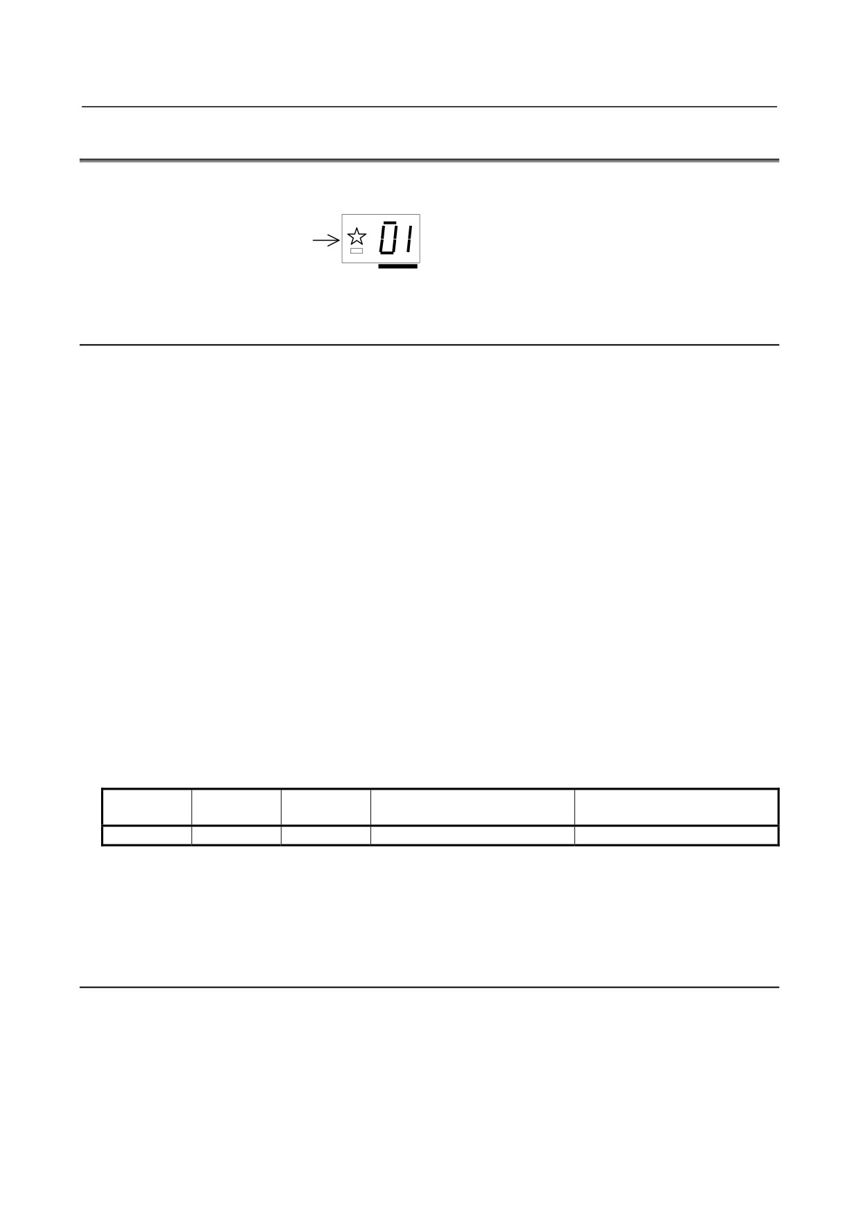
If an alarm occurs in the Spindle Amplifier, the ALM LED lights red in the STATUS display, and the
two-digit 7-segment LEDs indicate the alarm code.
The ALM LED
lights red.
status
Alarm code 01, 02 or above is indicated.
3.4.1
Alarm Code 01
The inside temperature of the motor is higher than the specified temperature.
(1)
If this alarm is issued during cutting (the motor temperature is high)
(a) Check the cooling state of the motor.
<1> If the cooling fan of the spindle motor is stopped, check the power supply of the cooling fan.
If the cooling fan is still inoperative, replace it with a new one.
<2> When a liquid-cooled motor is used, check the cooling system.
<3> When the ambient temperature of the spindle motor is higher than the specified temperature,
lower the ambient temperature to satisfy the specification.
(b) Recheck the cutting conditions.
(2)
If this alarm is issued under a light load (the motor temperature is high)
(a) When the frequency of acceleration/deceleration is too high
Set such a use condition that the average including output at acceleration/deceleration does not
exceed the continuous rating.
(b) The parameters specific to the motor are not correctly.
Referring to "FANUC AC SPINDLE MOTOR αi series Parameter Manual (B-65280EN),"
check the motor-specific parameters.
(3)
If this alarm is issued when the motor temperature is low
(a) The spindle motor feedback cable is faulty.
Replace the cable.
(b) The parameters specific to the motor are not set correctly.
Referring to "FANUC AC SPINDLE MOTOR αi series Parameter Manual (B-65280EN),"
check the motor-specific parameters.
FS16i
FS30i
For α series motor
For αi series motor
FS15i
FS0i-B/C
FS0i-D
3134
4134
4134
0
Motor-specific parameter
(c) The control printed circuit board is faulty.
Replace the control printed circuit board or spindle amplifier.
(d) The motor (internal thermostat) is faulty.
Replace the motor.
3.4.2
Alarm Code 02
The actual motor speed is largely deviated from the commanded speed.
(1) If this alarm is issued during motor acceleration
(a) The parameter setting of acceleration/deceleration time is incorrect.
Set the following parameter with the actual acceleration/deceleration time for your machine plus
some margin.
- 81 -
3.TROUBLESHOOTING AND
ACTION
TROUBLESHOOTING
B-65285EN/04
FS16i
FS30i
FS15i
Description
FS0i-B/C
FS0i-D
3082
4082
4082
Setting of acceleration/deceleration time
(b) The parameter for the speed detector is not set correctly.
Referring to "FANUC AC SPINDLE MOTOR αi series Parameter Manual (B-65280EN)," set a
correct value.
(2) If this alarm is issued at a heavy cutting load
(a) The cutting load has exceeded the motor output power.
Check the load meter indication, and review the use condition.
(b) The parameters for output restriction are not set correctly.
Check that the settings of the following parameters satisfy the machine and motor specifications:
FS16i
FS30i
FS15i
Description
FS0i-B/C
FS0i-D
3028
4028
4028
Output restriction pattern setting
3029
4029
4029
Output restriction value
(c) The parameters specific to the motor are not correctly.
Referring to "FANUC AC SPINDLE MOTOR αi series Parameter Manual (B-65280EN),"
check the motor-specific parameters.
3.4.3
Alarm Code 03
The fuse of the DC link has blown. (The voltage at the DC link is insufficient.) This alarm is checked when
emergency stop is cancelled.
(1) If this alarm is issued during spindle operation (rotation)
The fuse of the DC link inside the Spindle Amplifier has probably blown. So, replace the Spindle
Amplifier. This alarm may be caused by the following:
<1> Power lead short-circuited to ground
<2> Motor winding short-circuited to ground
<3> IGBT or IPM module failure
(2) If the Power Supply input magnetic contactor is once turned on and is turned off with this alarm when
emergency stop is cancelled or the CNC is started (When two spindles are connected, the magnetic
contactor may not be turned off.)
(a) The DC link wire is not connected.
Check the DC link wiring for errors.
(b) The fuse of the DC link inside the Spindle Amplifier has blown.
Replace the Spindle Amplifier.
3.4.4
Alarm Code 06
The temperature sensor is abnormal, or the temperature sensor cable is broken.
(1) The parameters specific to the motor are not correctly.
Referring to "FANUC AC SPINDLE MOTOR αi series Parameter Manual (B-65280EN)," check the
motor-specific parameters.
(2) Cable is faulty.
Feedback cable is faulty.
Replace the cable.
(3) The control printed-circuit board is faulty.
Replace the control printed-circuit board or spindle amplifier.
(4) A thermo sensor is faulty.
Replace the motor (thermo sensor).
- 82 -
3.TROUBLESHOOTING AND
B-65285EN/04
TROUBLESHOOTING
ACTION
3.4.5
Alarm Code 07
The motor rotates at a speed exceeding 115% (standard setting) of the maximum allowable speed.
(1) If this alarm is issued during spindle synchronization
If one of the motors operating in spindle synchronization is deactivated (SFR or SRV) and activated
again, the spindle motor may accelerate to its maximum rotation speed in order to eliminate the
position error accumulated while the motor is off, resulting in this alarm being issued.
Modify the ladder in such a way that this sequence will not be used.
(2) Spindle Amplifier is faulty.
Replace the Spindle Amplifier.
3.4.6
Alarm Code 09
The temperature of the heat sink of the Spindle Amplifier main circuit has risen abnormally. This alarm is
issued for αi SP22, αi SP30HV and later. With αi SP2.2 to αi SP15 and αi SP5.5HV to αi SP15HV,
however, Alarm 12 is issued for the same cause.
(1) If this alarm is issued during cutting (the heat sink temperature is high)
(a) If this alarm is issued when the load meter reads a value below the continuous rating of the
amplifier, check the cooling state of the heat sink.
<1> If the cooling fan is stopped, check the power supply (connector CX1A/B). If the cooling
fan is still inoperative, replace the Spindle Amplifier with a new one.
<2> When the ambient temperature is higher than the specified temperature, lower the ambient
temperature to satisfy the specification.
(b) When this alarm is issued because the load meter reads a value above the continuous rating of the
amplifier, improve the use method.
(c) When the heat sink on the back of the amplifier is too dirty, clean the heat sink, for example, by
blowing air. Consider the use of a structure that prevents the heat sink from being directly
exposed to coolant.
(2) If this alarm is issued under a light load (the heat sink temperature is high)
(a) When the frequency of acceleration/deceleration is too high
Set such a use condition that the average including output at acceleration/deceleration does not
exceed the continuous rating.
(b) The parameters specific to the motor are not set correctly.
Referring to "FANUC AC SPINDLE MOTOR αi series Parameter Manual (B-65280EN),"
check the motor-specific parameters.
(3) Poor installation of the control printed-circuit board
Be sure to push the faceplate as far as it will go. (This alarm may be displayed if one of the connectors
for connection between the control printed-circuit board and power printed-circuit board is detached.)
(4) If this alarm is issued when the heat sink temperature is low
Replace the Spindle Amplifier.
3.4.7
Alarm Code 10
The control power supply voltage decreases.
Troubleshooting when this alarm is issued
The control power supply, power cable, Power Supply, or Spindle Amplifier is defective.
Replace the control power supply, power cable, Power Supply, or Spindle Amplifier.
- 83 -
3.TROUBLESHOOTING AND
ACTION
TROUBLESHOOTING
B-65285EN/04
3.4.8
Alarm Code 12
An excessively large current flowed into the DC link of the main circuit.
With αi SP2.2 to αi SP15 and αi SP5.5HV to αi SP15HV, this alarm indicates that the power module (IPM)
of the main circuit detected an error such as an excessive load, overcurrent.
(1)
If this alarm is issued on αi SP2.2 to αi SP1 and αi SP5.5HV to αi SP15HV
Check alarm code 09 as well.
(2)
Poor installation of the control printed-circuit board
Be sure to push the faceplate as far as it will go. (This alarm may be displayed if one of the connectors
for connection between the control printed-circuit board and power printed-circuit board is detached.)
(3)
If this alarm is issued immediately after a spindle rotation command is specified
(a) The motor power lead is faulty.
Check for a short circuit between motor power leads and short-circuit to ground, and replace the
power lead as required.
(b) The motor winding has an insulation failure.
If the motor is short-circuited to ground, replace the motor.
(c) The parameters specific to the motor are not set correctly.
Referring to "FANUC AC SPINDLE MOTOR αi series Parameter Manual (B-65280EN),"
check the motor-specific parameters.
(d) The Spindle Amplifier is faulty.
A power element (IGBT, IPM) may be destroyed. Replace the Spindle Amplifier.
(4)
If this alarm is issued during spindle rotation
(a) A power element is destroyed.
A power element (IGBT, IPM) may be destroyed. Replace the Spindle Amplifier.
If the amplifier setting condition is not satisfied, or cooling is insufficient because the heat sink is
dirty, the power elements may be destroyed.
When the heat sink on the back of the amplifier is too dirty, clean the heat sink, for example, by
blowing air. Consider the use of a structure that prevents the heat sink from being directly
exposed to coolant.
For the installation condition, refer to "FANUC SERVO AMPLIFIER αi series Descriptions
(B-65282EN)."
(b) The parameters specific to the motor are not set correctly.
Referring to "FANUC AC SPINDLE MOTOR αi series Parameter Manual (B-65280EN),"
check the parameters specific to the motor.
(c) Speed sensor signal error
Check the spindle sensor signal waveform. If an error is found, make an adjustment or replace the
sensor as required.
3.4.9
Alarm Code 13
An error was detected in the CPU internal RAM.
Troubleshooting when this alarm is issued
The Spindle Amplifier is abnormal. Replace the Spindle Amplifier.
3.4.10 Alarm Code 14
Amplifier ID data inconsistent with series and edition of software was detected.
Troubleshooting when this alarm is issued
The Spindle Amplifier is abnormal. Replace the Spindle Amplifier.
- 84 -

3.TROUBLESHOOTING AND
B-65285EN/04
TROUBLESHOOTING
ACTION
3.4.11 Alarm Code 15
In output switching control or spindle switching control, the switching operation sequence was not executed
correctly.
This alarm is issued if one second or more elapses from the transition of a switch request signal (SPSL or
RSL) until a power lead state check signal (MCFN, MFNHG, RCH, or RCHHG) makes a transition.
(1) Troubleshooting when this alarm is issued
(a) The magnetic contactor (switch unit) for power lead switching is faulty.
If the contact is inoperative, check the power supply of the magnetic contactor. If the magnetic
contactor is still inoperative, replace the magnetic contactor.
(b) The I/O unit or wiring for checking the contact of the magnetic contactor is faulty.
If a defect is found in the I/O unit or wiring, replace the I/O unit or wiring.
(c) The sequence (ladder) is incorrect.
Modify the sequence so that switching is completed within 1 second.
3.4.12 Alarm Code 16
An error was found in a CPU internal RAM test by the Dual Check Safety function.
Troubleshooting when this alarm is issued
The Spindle Amplifier is abnormal. Replace the Spindle Amplifier.
3.4.13 Alarm Code 17
An error was detected in amplifier ID data.
Troubleshooting when this alarm is issued
The Spindle Amplifier control printed-circuit board becomes loose or the Spindle Amplifier
is
abnormal.
Check whether the Spindle Amplifier control printed-circuit board is mounted correctly.
When the board is mounted correctly, replace the Spindle Amplifier.
3.4.14 Alarm Code 18
A sum check is abnormal.
If this alarm is issued, replace the Spindle Amplifier or Spindle Amplifier control printed-circuit board.
3.4.15 Alarm Codes 19 and 20
The offset voltage of the phase U (alarm code 19) or phase V (alarm code 20) current detection circuit is
excessively high. A check is made when the power is turned on.
If this alarm is issued, replace the Spindle Amplifier. If this alarm is issued immediately after the Spindle
Amplifier control printed circuit board is replaced, check the plugging of the connectors between the power
unit and Spindle Amplifier control printed circuit board.
- 85 -
3.TROUBLESHOOTING AND
ACTION
TROUBLESHOOTING
B-65285EN/04
3.4.16 Alarm Code 21
The specified polarity of the position sensor is incorrect.
Troubleshooting when this alarm is issued
(a) Check the position sensor polarity parameter (bit 4 of parameter No. 4001).
(b) Check the feedback cable of the position sensor.
3.4.17 Alarm Code 22
Overcurrent exceeding the time rating of the Spindle Amplifier flowed.
Possible causes are a high frequency of acceleration/deceleration and high cutting load.
Troubleshooting when this alarm is issued
Ease the operation conditions.
3.4.18 Alarm Code 24
Serial communication data transferred between the CNC and Spindle Amplifier contains an error. (Note)
Troubleshooting when this alarm is issued
(a) Noise occurring between the CNC and Spindle Amplifier (connected via an electric cable) caused
an error in communication data.
Check the condition for maximum wiring length.
Referring to "Connection," in "FANUC SERVO AMPLIFIER αi series Descriptions
(B-65282EN)," check the condition of electric cable connection.
(b) Noise exercises an influence because a communication cable is bundled with the power lead.
If a communication cable is bundled with the power lead for the motor, separate them from each
other.
(c) A cable is faulty.
Replace the cable.
If an optical I/O link adapter is used, the optical link adapter or optical cable may be faulty.
(d) The Spindle Amplifier is faulty.
Replace the Spindle Amplifier or Spindle Amplifier control printed circuit board.
(e) The CNC is faulty.
Replace the board or module related to the serial spindle.
NOTE
This alarm is issued also if the CNC power is off. This is not a failure, though.
3.4.19 Alarm Code 27
The signal of the αi position coder is disconnected.
(1) If this alarm is issued when the motor is deactivated
(a) The setting of a parameter is incorrect.
Referring to "FANUC AC SPINDLE MOTOR αi series Parameter Manual (B-65280EN),"
check the parameter for sensor setting.
(b) The cable is disconnected.
If the connection of the feedback cable is correct, replace the cable.
(c) The Spindle Amplifier is faulty.
Replace the Spindle Amplifier or Spindle Amplifier control printed circuit board.
- 86 -
3.TROUBLESHOOTING AND
B-65285EN/04
TROUBLESHOOTING
ACTION
(2) If this alarm is issued when the cable is moved
(a) The connector has a bad contact, or the cable is disconnected.
The conductor may be broken. Replace the cable. If coolant has penetrated into the connector,
clean the connector.
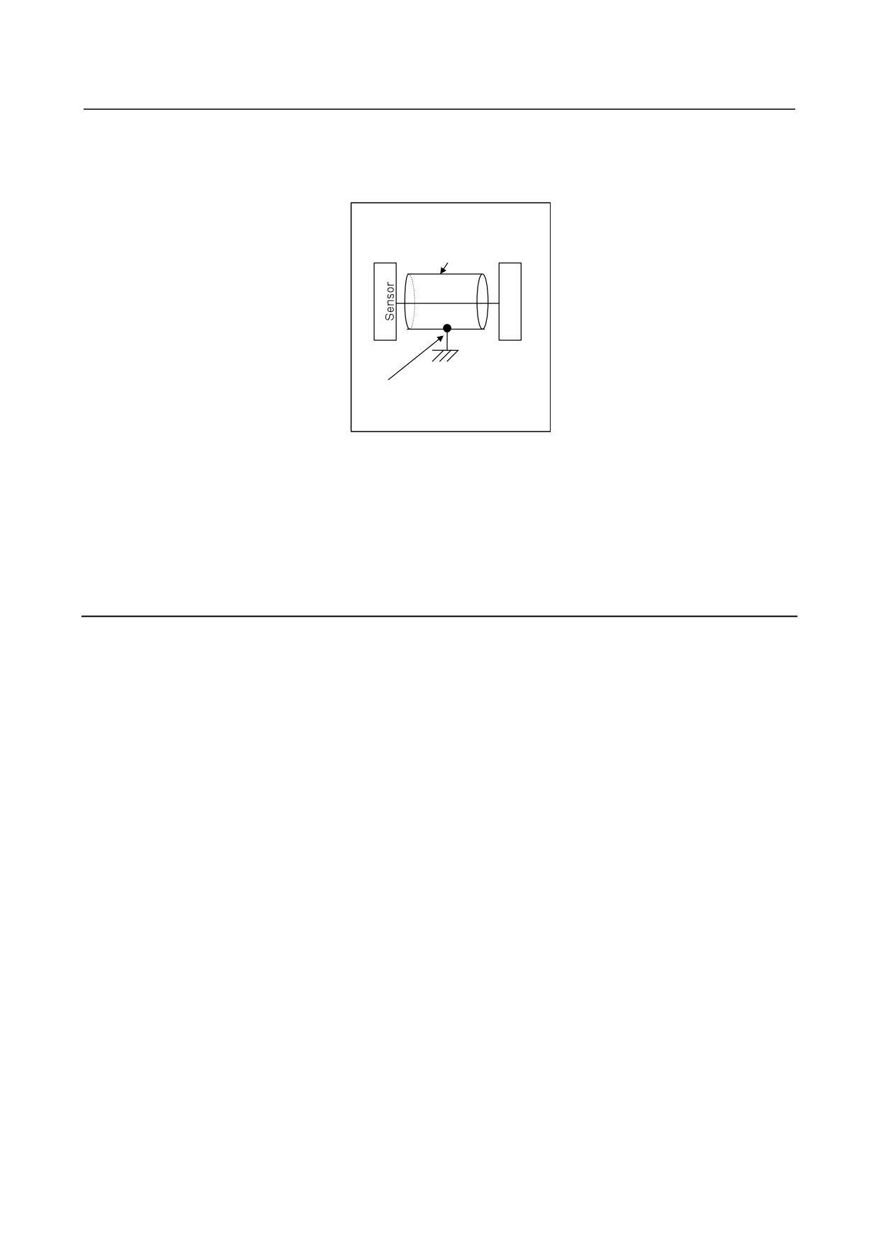
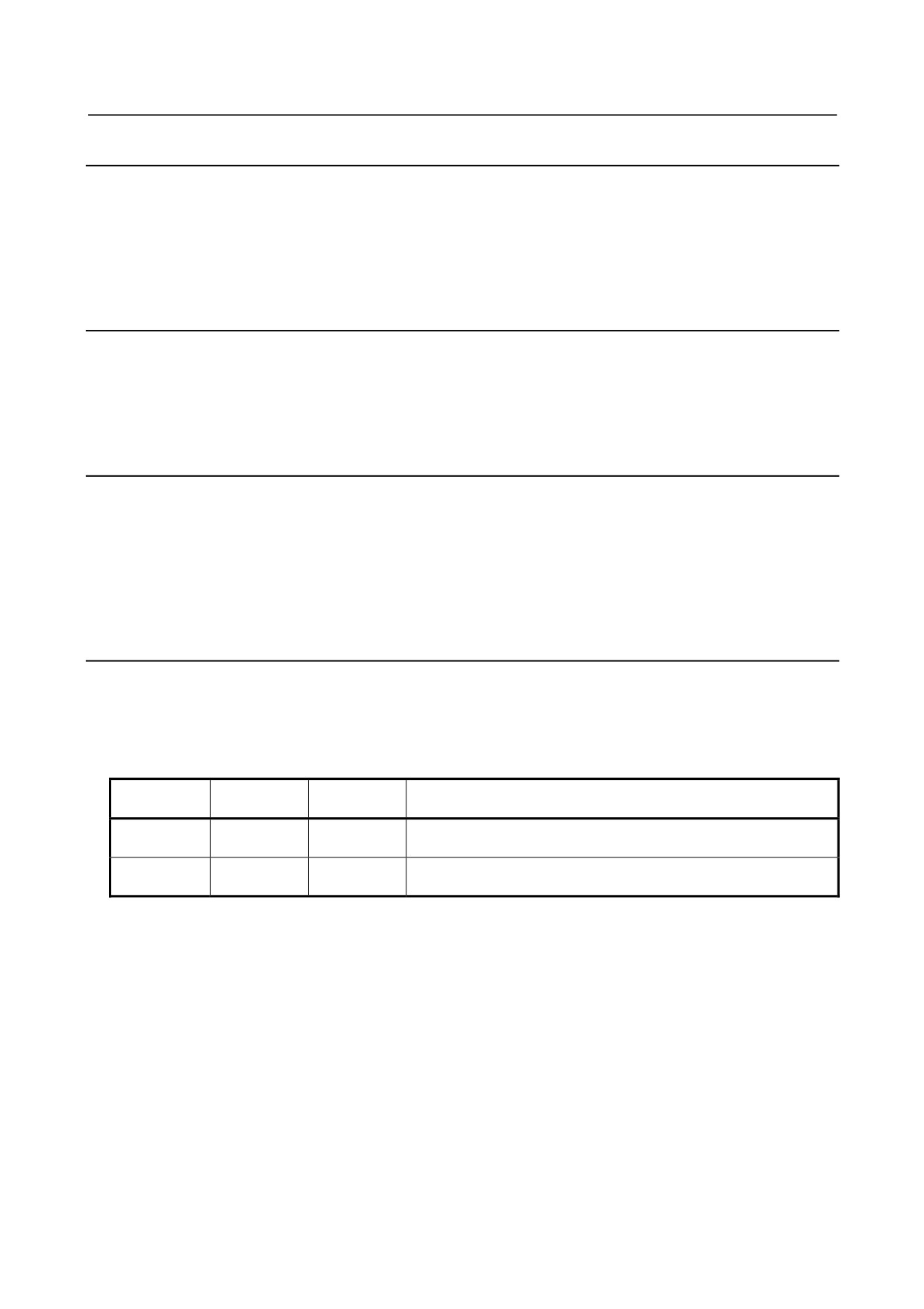
αi position coder
Shielded cable
S
P
Connected to the frame
ground via a cable clamp.
(3) If this alarm is issued when the motor rotates
(a) The shielding of the cable between the sensor and the Spindle Amplifier is faulty.
Referring to, "Connection," in "FANUC SERVO AMPLIFIER αi series Descriptions
(B-65282EN)," check the shielding of the cable.
(b) The signal cable is bundled with the servo motor power lead.
If the cable between the sensor and the Spindle Amplifier is bundled with the servo motor power
lead, separate them from each other.
3.4.20 Alarm Code 29
An excessive load (standard setting: load meter reading of 9 V) has been applied continuously for a certain
period (standard setting: 30 seconds).
(1) If this alarm is issued during cutting
Check the load meter, and review the cutting condition.
(2) If this alarm is issued during a stop
(a) The spindle is locked.
Check the sequence to see if the spindle is locked when a command for very slow movement is
specified or orientation is specified for the spindle.
(3) If the spindle does not rotate as specified (the spindle rotates at a very low speed) and this alarm is
issued
(a) The setting of a parameter is incorrect.
Referring to "FANUC AC SPINDLE MOTOR αi series Parameter Manual (B-65280EN),"
check the parameter for sensor setting.
(b) The phase sequence of the motor power lead is incorrect.
(c) The feedback cable of the motor has a problem.
Check if the phase A/B signals are connected correctly.
(d) The feedback cable of the motor is faulty.
Rotate the motor manually to see if a speed is indicated in the item of motor speed on the CNC
diagnosis screen or on the spindle check board. If no speed indication is provided, replace the
cable or spindle sensor (or motor).
(4) If the spindle does not rotate as specified (the spindle does not rotate at all) and this alarm is issued
(a) The power lead is abnormal.
Check if the motor power lead is connected normally. If spindle switching or output switching is
performed, check if the magnetic contactor is on.
(b) The Spindle Amplifier is faulty.
Replace the Spindle Amplifier.
- 87 -

3.TROUBLESHOOTING AND
ACTION
TROUBLESHOOTING
B-65285EN/04
3.4.21 Alarm Code 31
The motor failed to rotate as specified, and has stopped or is rotating at a very low speed.
(1) If the motor rotates at a very low speed and this alarm is issued
(a) The setting of a parameter is incorrect.
Referring to "FANUC AC SPINDLE MOTOR αi series Parameter Manual (B-65280EN),"
check the parameter for sensor setting.
(b) The phase sequence of the motor power lead is incorrect.
Check whether the phase sequence of the motor power lead is correct.
(c) The feedback cable of the motor has a problem.
Check if the phase A/B signals are connected correctly.
(d) The feedback cable of the motor is faulty.
Rotate the motor manually to see if a speed is indicated in the item of motor speed on the CNC
diagnosis screen or on the spindle check board. If no speed indication is provided, replace the
cable or spindle sensor (or motor).
(2) If the motor does not rotate at all and this alarm is issued
(a) The sequence for locking the spindle is incorrect.
Check the sequence to see if the spindle is locked.
(b) The power lead is faulty.
Check if the power lead is connected to the motor correctly. If spindle switching or winding
switching is performed, check if the magnetic contactor is on.
(c) The Spindle Amplifier is faulty.
Replace the Spindle Amplifier.
3.4.22 Alarm Code 32
LSI memory for serial communication is abnormal. A check is made when the power is turned on.
If this alarm is issued, replace the Spindle Amplifier or Spindle Amplifier control printed circuit board.
3.4.23 Alarm Code 34
Parameter data outside the specifiable range was set.
Troubleshooting when this alarm is issued
Connect the spindle check board.
The spindle check board displays "AL-34" and "F-xxx" alternately. "F-xxx" indicates a parameter
number outside the specifiable range. For the correspondence between the CNC parameter numbers
and "F-xxx," refer to "FANUC AC SPINDLE MOTOR αi series Parameter Manual (B-65280EN)."
3.4.24 Alarm Code 36
The error counter overflowed.
(1) The setting of a parameter is incorrect.
(a) The gear ratio set in a parameter is incorrect.
Check if an excessively large gear ratio is set.
(b) The setting of a position gain is incorrect.
If the gear ratio data is correct, increase the position gain.
- 88 -
3.TROUBLESHOOTING AND
B-65285EN/04
TROUBLESHOOTING
ACTION
FS16i
FS30i
FS15i
Description
FS0i-B/C
FS0i-D
3056 to 3059
4056 to4059
4056 to4059
Gear ratio between the spindle and motor
3060 to3063
4060 to4063
4060 to4063
Position gain at orientation
3065 to3068
4065 to4068
4065 to4068
Position gain in the servo mode/spindle synchronization
3069 to3072
4069 to4072
4069 to4072
Position gain in Cs contour control
(2) Sequence error
(a) Check if the motor is deactivated (by turning off SFR/SRV) in a position control mode (rigid
tapping, Cs contour control, or spindle synchronization).
3.4.25 Alarm Code 37
After emergency stop signal input, the motor is accelerated without being decelerated. This alarm is issued
also when the motor is not deactivated
(the motor is not decelerated completely) when the
acceleration/deceleration time (initial parameter setting: 10 seconds) has elapsed after emergency stop
signal input.
Troubleshooting when this alarm is issued
(a) The parameter setting of the speed detector is incorrect.
Referring to Chapter
1 in "FANUC AC SPINDLE MOTOR αi series Parameter Manual
(B-65280EN)," set a correct time.
(b) The parameter setting of an acceleration/deceleration time is not proper.
Check the parameter-set value and actual acceleration/ deceleration time, then set an actual
acceleration/deceleration time plus some margin.
FS16i
FS30i
FS15i
Description
FS0i-B/C
FS0i-D
3082
4082
4082
Acceleration/deceleration time setting
3.4.26 Alarm Code 41
The position where the one-rotation signal of the αi position coder is generated is incorrect.
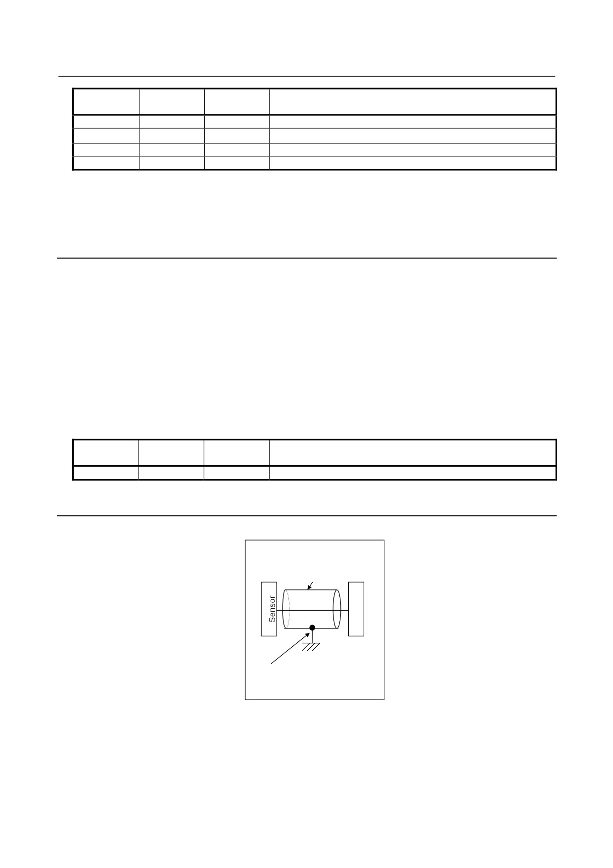
αi position coder
Shielded cable
S
P
Connected to the frame
ground via a cable clamp.
Troubleshooting when this alarm is issued
(a) The setting of a parameter is incorrect.
Referring to "FANUC AC SPINDLE MOTOR αi series Parameter Manual (B-65280EN)," check the
parameter for sensor setting.
(b) The αi position coder is faulty.
Observe the Z signal of the position coder. If the signal is not generated per rotation, replace the
position coder.
- 89 -
3.TROUBLESHOOTING AND
ACTION
TROUBLESHOOTING
B-65285EN/04
(c) The shielding of the cable between the sensor and Spindle Amplifier is faulty.
Referring to "Connection," in "FANUC SERVO AMPLIFIER αi series Descriptions (B-65282EN),"
check the shielding of the cable.
(d) The signal cable is bundled with the servo motor power lead.
If the cable between the sensor and Spindle Amplifier is bundled with the servo motor power lead,
separate them from each other.
(e) The Spindle Amplifier is faulty.
Replace the Spindle Amplifier or Spindle Amplifier control printed circuit board.
3.4.27 Alarm Code 42
The one-rotation signal of the αi position coder is not generated.
Troubleshooting when this alarm is issued
(a) The setting of a parameter is incorrect.
Referring to "FANUC AC SPINDLE MOTOR αi series Parameter Manual (B-65280EN)," check the
parameter for sensor setting.
(b) The αi position coder is faulty.
Check the check pin PSD on the spindle check board. If the signal is not generated per rotation, replace
the connection cable and position coder.
(c) The Spindle Amplifier is faulty.
Replace the Spindle Amplifier or Spindle Amplifier control printed circuit board.
3.4.28 Alarm Code 43
The position coder signal of the master spindle used in differential spindle speed control is disconnected.
For troubleshooting when this alarm is issued, see the subsection about alarm code 27.
3.4.29 Alarm Code 46
The one-rotation signal of the position coder cannot be detected normally during thread cutting.
Troubleshoot as in the case of alarm code 41.
3.4.30 Alarm Code 47
The count value of αi position coder signal pulses is abnormal.
Phases A and B for the position coder have a feedback pulse count of 4096 p/rev per spindle rotation. The
Spindle Amplifier checks the pulse counts of phases A and B equivalent to the position coder each time a
one-rotation signal is generated. The alarm is issued when a pulse count beyond the specified range is
detected.
(1) If this alarm is issued when the cable is moved (as in the case where the spindle moves)
The conductor may be broken. Replace the cable. If coolant has penetrated into the connector, clean
the connector.
(2) Troubleshooting in other cases
(a) The setting of a parameter is incorrect.
Referring to "FANUC AC SPINDLE MOTOR αi series Parameter Manual (B-65280EN),"
check the parameter for sensor setting.
- 90 -
3.TROUBLESHOOTING AND
B-65285EN/04
TROUBLESHOOTING
ACTION
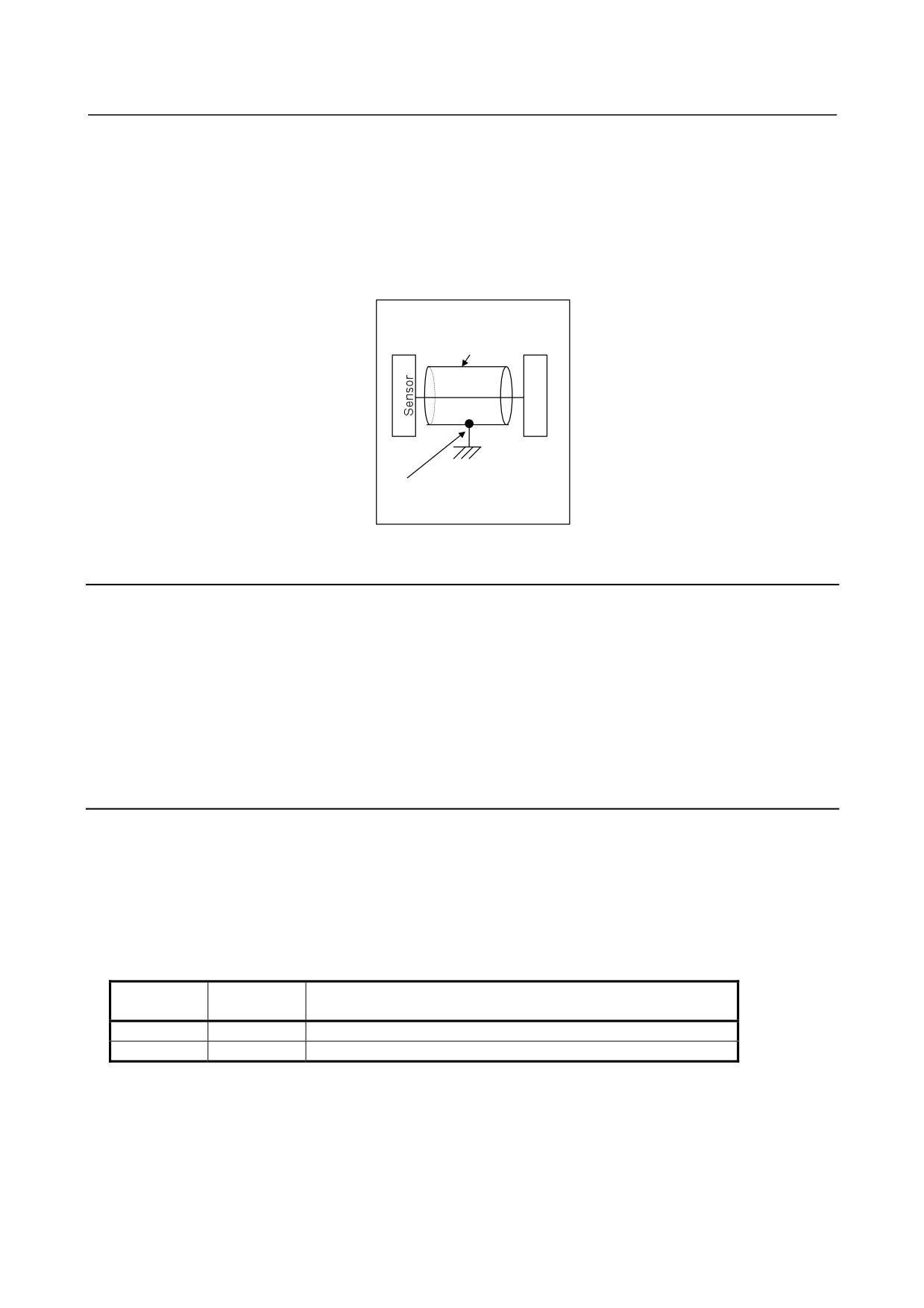
(b) The shielding of the cable between the sensor and Spindle Amplifier is faulty.
Referring to "Connection," in "FANUC SERVO AMPLIFIER αi series Descriptions
(B-65282EN)," check the shielding of the cable.
(c) The signal cable is bundled with the servo motor power lead.
If the cable between the sensor and Spindle Amplifier is bundled with the servo motor power lead,
separate them from each other.
(d) The Spindle Amplifier is faulty.
Replace the Spindle Amplifier or Spindle Amplifier control printed circuit board.
αi position coder
Shielded cable
S
P
Connected to the frame
ground via a cable clamp.
3.4.31 Alarm Code 49
In differential spindle speed control, the speed of the master spindle converted to the motor speed of the
slave spindle exceeded the allowable range.
Troubleshooting when this alarm is issued
The master spindle speed is converted to the motor speed of the slave spindle by multiplying the
master spindle speed by the gear ratio between the slave spindle and motor. Check whether the
converted spindle speed exceeds the maximum motor speed and operate the machine so that the
maximum motor speed is not exceeded.
3.4.32 Alarm Code 50
A value obtained by internal calculation in spindle synchronization exceeded the allowable range.
Troubleshooting when this alarm is issued
(a) The setting of parameters for gear ratio setting is incorrect.
Check if an excessively large gear ratio is set.
(b) Position gain setting limit
If correct gear ratio data is set, increase the position gain value in spindle synchronization.
FS16i
FS30i
Description
FS0i-B/C
FS0i-D
4056 to 4059
4056 to 4059
Gear ratio between the spindle and motor
4065 to 4068
4065 to 4068
Position gain in the servo mode/spindle synchronization
- 91 -

3.TROUBLESHOOTING AND
ACTION
TROUBLESHOOTING
B-65285EN/04
3.4.33 Alarm Codes 52 and 53
The synchronization signal (ITP) in communication data transferred to and from the CNC stopped.
Troubleshooting when this alarm is issued
(a) The Spindle Amplifier is faulty.
Replace the Spindle Amplifier or Spindle Amplifier control printed circuit board.
(b) The CNC is faulty.
Replace the board or module related to the serial spindle.
3.4.34 Alarm Code 54
A large current flowing in the motor for a long time was detected.
Troubleshoot as in the case of alarm code 29.
3.4.35 Alarm Code 55
In spindle switching control or output switching control, a mismatch between the switching request signal
(SPSL or RSL) and the power lead state check signal (MCFN, MFNHG, RCH, or RCHHG) continues
during motor activation.
Troubleshooting when this alarm is issued
(a) The magnetic contactor (switch unit) for power lead switching is faulty.
If the contact is inoperative, check the power supply of the magnetic contactor. If the magnetic
contactor is still inoperative, replace the magnetic contactor.
(b) The I/O unit or wiring for checking the contact of the magnetic contactor is faulty.
If a defect is found in the I/O unit or wiring, replace the I/O unit or wiring.
(c) The sequence (ladder) is incorrect.
Modify the sequence so that switching is not performed during activation. For details of the signals,
refer to "FANUC SERVO AMPLIFIER αi series Descriptions (B-65282EN)."
3.4.36 Alarm Code 56
The cooling fan for the control circuit section has stopped.
(a) Poor installation of the control printed-circuit board
Be sure to push the faceplate as far as it will go. (This alarm may be displayed if one of the connectors
for connection between the control printed-circuit board and power printed-circuit board is detached.)
(b) Replace the Spindle Amplifier or its internal cooling fan.
3.4.37 Alarm Code 61
The difference in position between the semi-closed side and closed side exceeded the setting level
(parameter No. 4354) for the dual position feedback function.
Troubleshooting when this alarm is issued
(a) When this alarm is issued at the start of the machine, there may be a setting error in a sensor-related
parameter or motor-end position feedback conversion coefficient parameter.
Check whether conversion coefficient parameters Nos. 4171 and 4172 (in high gear) and Nos. 4173
and 4174 (in low gear) are set correctly. Also, refer to the FANUC AC SPINDLE MOTOR ai series
Parameter Manual (B-65280EN) to check the settings of the sensor-related parameters.
- 92 -
3.TROUBLESHOOTING AND
B-65285EN/04
TROUBLESHOOTING
ACTION
(b) When the conversion coefficients are set correctly, the level set for parameter No. 4354 may be too
low.
(c) When this alarm is issued for a system which has been operating normally, there may be slippage
between the motor and spindle. Check the machine.
(d) When this alarm is intermittently issued for a system which has been operating normally, a count error
may occur in the motor-end or spindle-end position feedback signal due to noise.
3.4.38 Alarm Code 65
A magnetic pole detection error occurred. This spindle alarm is issued for the BiS Series spindle motors
(synchronous spindle motors).
Troubleshooting when this alarm is issued
When this alarm is issued at the start, possible causes are all of (a) to (f) below. When the machine has
been operating normally, possible causes are (d), (e), and (f).
(a) There is a setting error in a parameter (number of teeth of a motor sensor or number of phases of
a motor).
Check whether the settings of the parameters of the number of teeth of the motor sensor (bits 2, 1,
and 0 of parameter No. 4011 and parameter No. 4334) and the number of phases of the motor
(bits 7 and 3 of parameter No. 4011 and parameter No. 4368) are correct.
(b) The phase sequence of the motor power lead differs from that of connection of motor sensor
feedback.
(c) The motor power lead is not connected.
(d) The motor is locked and cannot move. Alternatively, the excitation current is low and the motor
cannot move smoothly due to the effect of friction.
Detect the magnetic pole when the motor can move smoothly.
(e) The motor sensor or rotor shaft slips and the phase relationship between the motor sensor and
rotor changes.
(f) A count error occurs in the motor feedback signal due to the effect of noise.
3.4.39 Alarm Code 66
An error occurred during communication (connector JX4) between spindle and amplifier.
Troubleshooting when this alarm is issued
(a) Check the connection between the spindle and amplifier.
(b) Replace the cable.
3.4.40 Alarm Code 67
The reference position return command was issued for the slave axis in the spindle EGB mode.
Troubleshooting when this alarm is issued
(a) Reference position return cannot be performed in the spindle EGB mode (G81). Before performing
reference position return, turn the EGB mode off (G80).
3.4.41 Alarm Code 69
This alarm can be issued only when Dual Check Safety is in use.
The alarm occurs if, in safety signal mode C (a guard open request was entered to open the guard), the
spindle motor rotation speed exceeds the safety speed.
- 93 -
3.TROUBLESHOOTING AND
ACTION
TROUBLESHOOTING
B-65285EN/04
Troubleshooting when this alarm is issued
(a) If the guard is open, observe the safety speed.
(b) Check the safety speed parameter.
(c) Replace the Spindle Amplifier control printed-circuit board.
3.4.42 Alarm Code 70
This alarm can be issued only when Dual Check Safety is in use.
The spindle amplifier connection status does not match the hardware setting.
Troubleshooting when this alarm is issued
(a) Check the Spindle Amplifier connection and its setting.
(b) Replace the CPU card or Spindle Amplifier control printed-circuit board.
3.4.43 Alarm Code 71
This alarm can be issued only when Dual Check Safety is in use.
A safety parameter error occurred.
Troubleshooting when this alarm is issued
(a) Re-set the safety parameter.
(b) Replace the CPU card or Spindle Amplifier control printed-circuit board.
3.4.44 Alarm Code 72
This alarm can be issued only when Dual Check Safety is in use.
The result of the spindle amplifier speed check does not match the result of the CNC speed check.
If the alarm occurs, replace the CPU card in the CNC or the Spindle Amplifier control printed-circuit board.
3.4.45 Alarm Code 73
The signal of the motor sensor is disconnected.
(1) If this alarm is issued when the motor is deactivated
(a) The setting of a parameter is incorrect.
Referring to "FANUC AC SPINDLE MOTOR αi series Parameter Manual (B-65280EN),"
check the parameter for sensor setting.
(b) The cable is disconnected.
Replace the cable.
(c) The sensor is not adjusted correctly.
Adjust the sensor signal. If the sensor signal cannot be adjusted correctly, or the sensor signal is
not observed, replace the connection cable and sensor.
(d) The Spindle Amplifier is faulty.
Replace the Spindle Amplifier or Spindle Amplifier control printed circuit board.
(2) If this alarm is issued when the cable is moved (as in the case where the spindle moves)
The conductor may be broken. Replace the cable. If coolant has penetrated into the connector, clean
the connector.
- 94 -
3.TROUBLESHOOTING AND
B-65285EN/04
TROUBLESHOOTING
ACTION
(3) If this alarm is issued when the motor rotates
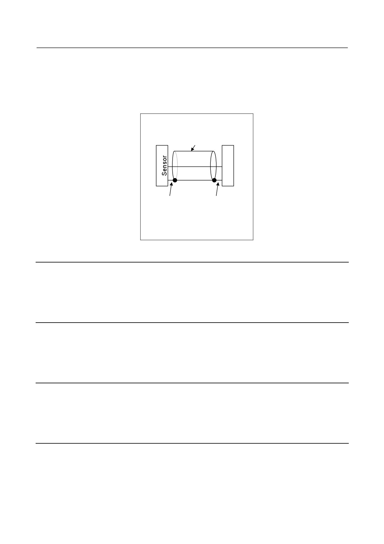
(a) The shielding of the cable between the sensor and the Spindle Amplifier is faulty.
Referring to, "Connection," in "FANUC SERVO AMPLIFIER αi series Descriptions
(B-65282EN)," check the shielding of the cable.
(b) The signal cable is bundled with the servo motor power lead.
If the cable between the sensor and the Spindle Amplifier is bundled with the servo motor power
lead, separate them from each other.
αiMZ or αiBZ sensor
Shielded cable
S
P
The cable is
The cable is
connected to the
connected to
pin specified in the
pin 10 on the
specifications on
SP side.
the sensor side.
3.4.46 Alarm Code 74
This alarm can be issued only when Dual Check Safety is in use.
The CPU test failed to end normally.
When this alarm is issued, Replace the Spindle Amplifier or Spindle Amplifier control printed circuit board.
3.4.47 Alarm Code 75
This alarm can be issued only when Dual Check Safety is in use.
An error occurred in the CRC test.
When this alarm is issued, Replace the Spindle Amplifier or Spindle Amplifier control printed circuit board.
3.4.48 Alarm Code 76
This alarm can be issued only when Dual Check Safety is in use.
The spindle safety function has not been executed.
If the alarm occurs, replace the Spindle Amplifier control printed-circuit board.
3.4.49 Alarm Code 77
This alarm can be issued only when Dual Check Safety is in use.
The result of the spindle amplifier axis number check does not match the result of the CNC axis number
check.
If the alarm occurs, replace the CPU card in the CNC or the Spindle Amplifier control printed-circuit board.
- 95 -
3.TROUBLESHOOTING AND
ACTION
TROUBLESHOOTING
B-65285EN/04
3.4.50 Alarm Code 78
This alarm can be issued only when Dual Check Safety is in use.
The result of spindle amplifier safety parameter check does not match the result of the CNC safety
parameter check.
If the alarm occurs, replace the CPU card in the CNC or the Spindle Amplifier control printed-circuit board.
3.4.51 Alarm Code 79
This alarm can be issued only when Dual Check Safety is in use.
An abnormal operation was detected in the initial test.
When this alarm is issued, Replace the Spindle Amplifier or Spindle Amplifier control printed circuit board.
3.4.52 Alarm Code 80
A spindle alarm was issued for the destination amplifier in inter-Spindle Amplifier communication
(connector JX4).
Troubleshooting when this alarm is issued
(a) There is no problem with the Spindle Amplifier to which this alarm is issued. Check the spindle alarm
in the destination amplifier and take appropriate action.
3.4.53 Alarm Code 81
The position where the one-rotation signal of the motor sensor is generated is incorrect.
(1) If the external one-rotation signal is used
(a) The settings of parameters are incorrect.
Check that the gear ratio data matches the specification of the machine.
FS16i
FS30i
FS15i
Description
FS0i-B/C
FS0i-D
3171
4171
4171
Denominator of gear ratio between motor sensor and spindle
3173
4173
4173
3172
4172
4172
Numerator of gear ratio between motor sensor and spindle
3174
4174
4174
(b) Slippage between the spindle and motor
Check that there is no slippage between the spindle and motor. The external one-rotation signal is
not applicable to V-belt connection.
(2) Troubleshooting in other cases
(a) The setting of a parameter is incorrect.
Referring to "FANUC AC SPINDLE MOTOR αi series Parameter Manual (B-65280EN),"
check the parameter for sensor setting.
(b) A sensor (αiMZ sensor or αiBZ sensor) is not adjusted correctly.
Adjust the sensor signal. If the sensor signal cannot be adjusted correctly, or the sensor signal is
not observed, replace the connection cable and sensor.
(c) The shielding of the cable between the sensor and Spindle Amplifier is faulty.
Referring to "Connection," in "FANUC SERVO AMPLIFIER αi series Descriptions
(B-65282EN)," check the shielding of the cable.
- 96 -
3.TROUBLESHOOTING AND
B-65285EN/04
TROUBLESHOOTING
ACTION
(d) The signal cable is bundled with the servo motor power lead.
If the cable between the sensor and Spindle Amplifier is bundled with the servo motor power lead,
separate them from each other.
(e) The Spindle Amplifier is faulty.
Replace the Spindle Amplifier or Spindle Amplifier control printed circuit board.
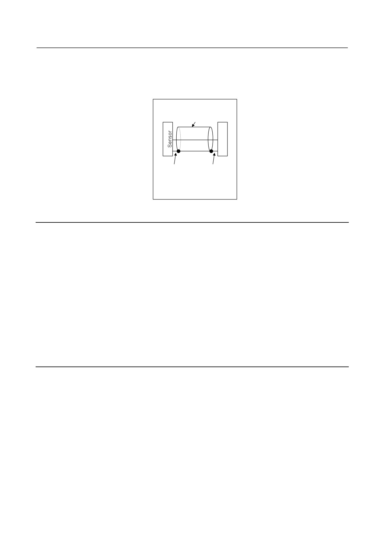
αiMZ or αiBZ sensor
Shielded cable
S
P
The cable is
The cable is
connected to the
connected to
pin specified in the
pin 10 on the
specifications on
SP side.
the sensor side.
3.4.54 Alarm Code 82
The one-rotation signal of the motor sensor is not generated.
Troubleshooting when this alarm is issued
(a) The setting of a parameter is incorrect.
Referring to "FANUC AC SPINDLE MOTOR αi series Parameter Manual (B-65280EN)," check the
parameter for sensor setting.
(b) The αiMZ sensor or αiBZ sensor is not adjusted correctly.
Adjust the sensor. If the sensor cannot be adjusted or the signal is not observed, replace the connection
cable and sensor.
(c) The external one-rotation signal is faulty.
Check the check pin EXTSC1 on the spindle check board. If the signal is not generated per rotation,
replace the connection cable and position coder.
(d) The Spindle Amplifier is faulty.
Replace the Spindle Amplifier or Spindle Amplifier control printed circuit board.
3.4.55 Alarm Code 83
The Spindle Amplifier checks the pulse counts of phases A and B each time a one-rotation signal is
generated. The alarm is issued when a pulse count beyond the specified range is detected.
(1) If this alarm is issued when the cable is moved (as in the case where the spindle moves)
The conductor may be broken. Replace the cable. If coolant has penetrated into the connector, clean
the connector.
(2) Troubleshooting in other cases
(a) The setting of a parameter is incorrect.
Referring to "FANUC AC SPINDLE MOTOR αi series Parameter Manual (B-65280EN),"
check the parameter for sensor setting.
(b) The αiMZ sensor or αiBZ sensor is not adjusted correctly.
Adjust the sensor. If the sensor cannot be adjusted or the signal is not observed, replace the
connection cable and sensor.
(c) The shielding of the cable between the sensor and Spindle Amplifier is faulty.
Referring to "Connection," in "FANUC SERVO AMPLIFIER αi series Descriptions
(B-65282EN)," check the shielding of the cable.
- 97 -
3.TROUBLESHOOTING AND
ACTION
TROUBLESHOOTING
B-65285EN/04
(d) The signal cable is bundled with the servo motor power lead.
If the cable between the sensor and Spindle Amplifier is bundled with the servo motor power lead,
separate them from each other.
(e) The Spindle Amplifier is faulty.
Replace the Spindle Amplifier or Spindle Amplifier control printed circuit board.
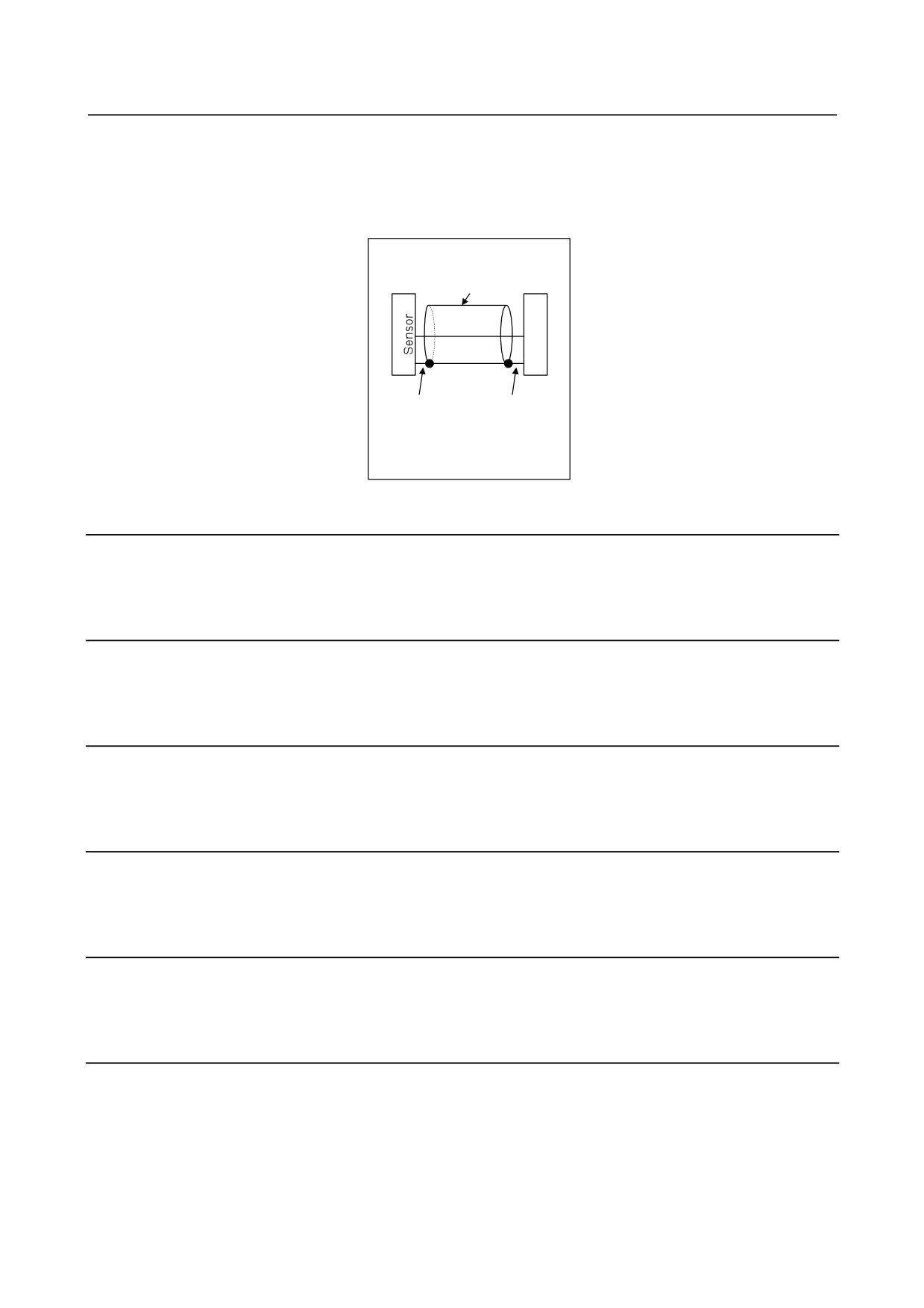
αiMZ or αiBZ sensor
Shielded cable
S
P
The cable is
The cable is
connected to the
connected to
pin specified in the
pin 10 on the
specifications on
SP side.
the sensor side.
3.4.56 Alarm Code 84
The spindle sensor signal was disconnected.
Refer to Alarm Code 73 for this alarm trouble shooting.
3.4.57 Alarm Code 85
The one-rotation signal of the spindle sensor occurred in an incorrect location.
Refer to Alarm Code 81 for this alarm trouble shooting.
3.4.58 Alarm Code 86
No spindle sensor one-rotation signal occurred.
Refer to Alarm Code 82 for this alarm trouble shooting.
3.4.59 Alarm Code 87
A spindle sensor signal is abnormal.
Refer to Alarm Code 83 for this alarm trouble shooting.
3.4.60 Alarm Code 88
The heat sink cooling fan is not running.
If this alarm is issued, replace the Spindle Amplifier heat sink cooling fan.
3.4.61 Alarm Code 89
The submodule SM (SSM) is abnormal. This spindle alarm is issued for the BiS Series spindle motors
(synchronous spindle motors).
When this alarm is issued at the start, possible causes are all of (a) to (d) below. When the machine has been
operating normally, possible causes are (c) and (d).
- 98 -
3.TROUBLESHOOTING AND
B-65285EN/04
TROUBLESHOOTING
ACTION
Troubleshooting when this alarm is issued
(a) The Spindle Amplifier does not support the SSM.
Replace the Spindle Amplifier.
(b) The SSM is not mounted or connected.
Check the connection of the interface signal cable between JYA4 (Spindle Amplifier) and CX31
(SSM).
(c) The interface signal between the Spindle Amplifier and SSM is disconnected.
Check the connection of the interface signal cable between JYA4 (Spindle Amplifier) and CX31
(SSM).
(d) The SSM is faulty.
Replace the SSM.
3.4.62 Alarm Code 90
An unexpected rotation state (state in which the polarity in the torque command differs that of acceleration)
was detected. This spindle alarm is issued for the BiS Series spindle motors (synchronous spindle motors).
When this alarm is issued at the start, possible causes are all of (a) to (d) below. When the machine has been
operating normally, it is highly possible that the cause is (c) or (d).
Troubleshooting when this alarm is issued
(a) There is a setting error in a parameter (number of teeth of the motor sensor or number of phases of the
motor).
Refer to the FANUC AC SPINDLE MOTOR αi series Parameter Manual (B-65280EN) to check the
relevant parameters.
(b) There is a setting error in an AMR offset-related parameter (No. 4084 or 4085).
Parameter No. 4084 (AMR offset) is adjusted for each machine. Readjust this parameter when the
phase relationship between the magnetic pole 0-deg position of the rotor and the one-rotation signal
position of the sensor changes due to the replacement of the sensor or slippage of the shaft or when the
parameter is loaded from another machine.
Parameter No. 4085 is provided for AMR offset adjustment. Normally, this parameter must be set to
"0".
(c) When this alarm is issued after the spindle is banged, a possible cause is a change to the phase
relationship between the motor sensor and rotor due to slippage of the motor sensor or rotor shaft.
(d) A count error occurs in the motor sensor due to noise.
Apply appropriate countermeasures against noise.
3.4.63 Alarm Code 91
A count error occurred for the magnetic pole position (a large difference between the magnetic pole position
at the one-rotation signal position and the setting of parameter No. 4084 (AMR offset) was detected). This
spindle alarm is issued for the BiS Series spindle motors (synchronous spindle motors).
When this alarm is issued at the start, possible causes are both (a) and (b) below. When the machine has
been operating normally, check (b) and take appropriate action.
Troubleshooting when this alarm is issued
(a) There is a setting error in a parameter (number of teeth of the motor sensor or number of phases of the
motor).
Refer to the FANUC AC SPINDLE MOTOR αi series Parameter Manual (B-65280EN) to check the
relevant parameters.
(b) An unnecessary one-rotation signal is generated or a count error occurs for feedback pulses due to
slippage of the sensor ring or noise.
Check whether the motor sensor slips. When there is no problem with the motor sensor, take
appropriate countermeasures against noise.
- 99 -
3.TROUBLESHOOTING AND
ACTION
TROUBLESHOOTING
B-65285EN/04
3.4.64 Alarm Code 92
The actual motor speed exceeded the overspeed level corresponding to the velocity command.
When this alarm is issued at the start, possible causes are all of (a) to (c) below. When the machine has been
operating normally, it is highly possible that the cause is noise in (c).
Troubleshooting when this alarm is issued
(a) There is a setting error in a parameter (number of teeth of the motor sensor or number of phases of the
motor).
Refer to the FANUC AC SPINDLE MOTOR αi series Parameter Manual (B-65280EN) to check the
relevant parameters.
(b) When a BiS Series spindle motor (synchronous spindle motor) is driven, there is a setting error in an
AMR offset-related parameter (No. 4084 or 4085).
Parameter No. 4084 (AMR offset) is adjusted for each machine. Readjust this parameter when the
phase relationship between the magnetic pole 0-deg position of the rotor and the one-rotation signal
position of the sensor changes due to the replacement of the sensor or slippage of the shaft or when the
parameter is loaded from another machine.
Parameter No. 4085 is provided for AMR offset adjustment. Normally, this parameter must be set to
"0".
(d) A count error occurs in the motor sensor due to noise.
Apply appropriate countermeasures against noise.
3.4.65 Alarm Codes A, A1, and A2
The control program is not running.
An error was detected when the control program was running.
(1) If this alarm is issued when the spindle amplifier power is switched on
(a) Wrong software specification
(b) Defective printed-circuit board
Replace the Spindle Amplifier or Spindle Amplifier control printed-circuit board.
(2) If this alarm is issued when the motor is active.
(a) Influence by noise
Referring to "Installation" in "FANUC SERVO AMPLIFIER αi series Descriptions
(B-65282EN)," check the grounding wire. If the spindle sensor signal wire is bundled together
with any motor power wire, separate them.
3.4.66 Alarm Code b0
An error occurred in communication between amplifiers (Spindle Amplifier, Servo Amplifier, and Power
Supply).
Troubleshooting when this alarm is issued
(1) If this alarm is issued immediately after the power supply of CNC is turned on
(a) Check the way the connectors are coupled.
Normally, CXA2A and CXA2B must be coupled.
(b) The cable is defective.
Check the connection pin number. If there is any problem, correct it.
Alternatively, replace the cable.
(c) The Spindle Amplifier, Servo Amplifier, or Power Supply is defective.
Replace the Spindle Amplifier, Servo Amplifier, or Power Supply. Alternatively, replace the
Spindle Amplifier, Servo Amplifier, or Power Supply control printed-circuit board.
- 100 -

3.TROUBLESHOOTING AND
B-65285EN/04
TROUBLESHOOTING
ACTION
3.4.67 Alarm Codes C0,C1, and C2
An error occurred in serial communication data between the CNC and Spindle Amplifier.
Troubleshooting when this alarm is issued
(a) The Spindle Amplifier is defective.
Replace the Spindle Amplifier or Spindle Amplifier control printed-circuit board.
(b) The CNC is defective.
Replace the board or module related to the serial spindle.
3.4.68 Alarm Code C3
In spindle switching, a mismatch is found between the switching request signal (SPSL) and the internal
status of the motor/spindle sensor signal switching circuit (submodule SW).
Troubleshooting when this alarm is issued
The submodule SW (SSW) is defective.
Replace the submodule SW (SSW).
3.4.69 Alarm Code C4
An invalid learning cycle is set in learning control in the time synchronization mode.
Troubleshooting when this alarm is issued
(a) Check whether the value specified in the velocity command is appropriate.
(b) Check whether the setting of the learning cycle (parameter No. 4425) is within a range between 20 and
4800.
3.4.70 Alarm Code C5
An invalid value is set for the highest or lowest degree of a dynamic characteristic compensation element in
learning control.
Troubleshooting when this alarm is issued
Decrease the setting of the highest (parameter No. 4427) or lowest (parameter No. 4428) of dynamic
characteristic compensation element Gx.
3.4.71 Alarm Code C7
An invalid reference angle cycle is set in learning control in the angle synchronization mode.
Troubleshooting when this alarm is issued
Increase the setting of parameter No. 4425 (number of divisions per cycle) in learning control.
3.4.72 Alarm Code C8
In spindle synchronization, the speed deviation (difference between the specified speed at the spindle end
calculated based on the position error and position gain and the actual speed) exceeded the alarm detection
level (parameter No. 4515).
- 101 -