FANUC AC SERVO MOTOR ai series, AC SPINDLE MOTOR ai series, SERVO AMPLIFIER ai series. MAINTENANCE MANUAL - page 2
3.START-UP PROCEDURE
START-UP PROCEDURE
B-65285EN/04
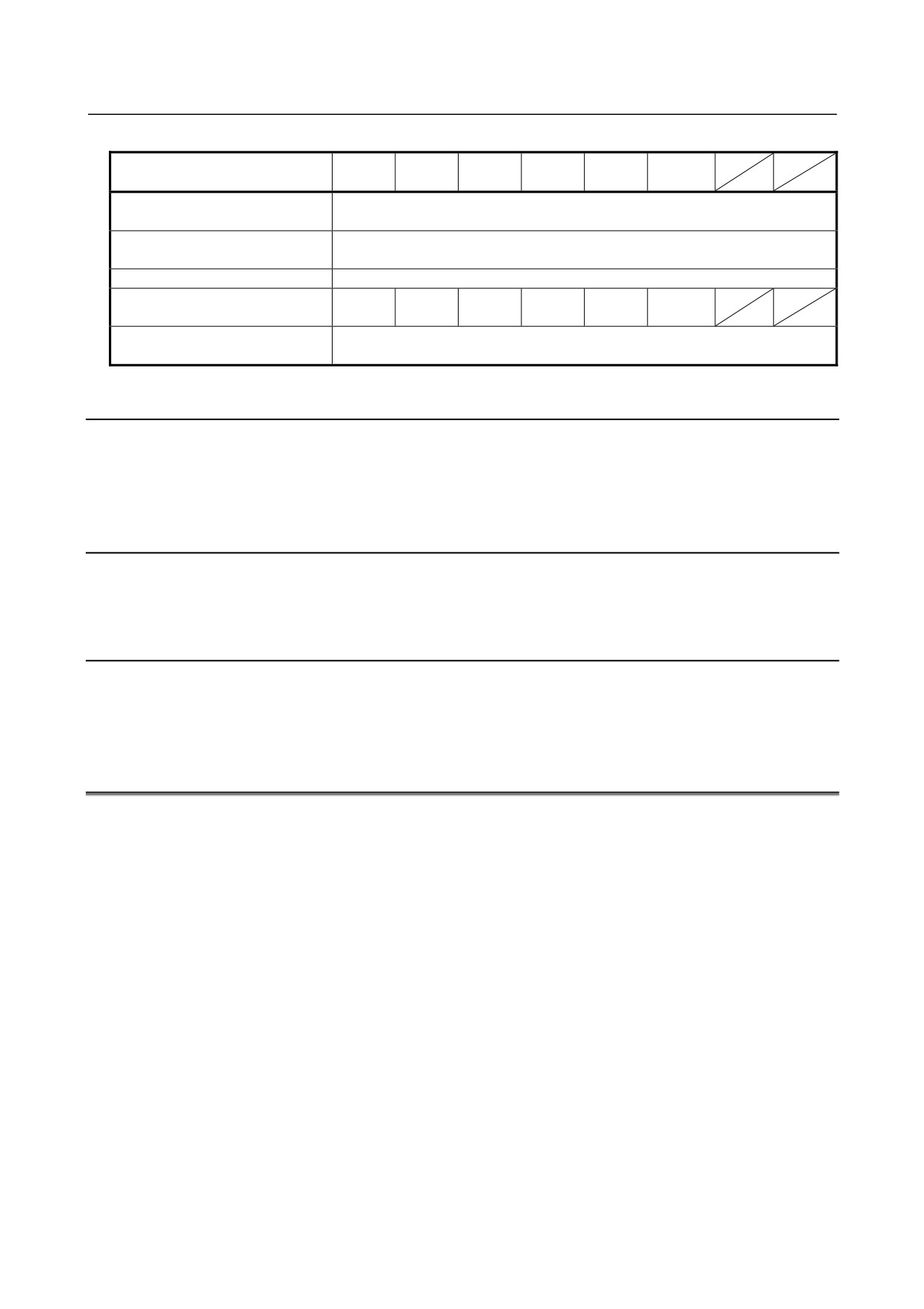
Table 3.2.1 (d) AC power voltage specifications (200-V input type)
αiPS
αiPS
αiPS
αiPS
αiPS
αiPS
Model
11HV
18HV
30HV
45HV
60HV
75HV
Nominal voltage rating
400 to 480VAC -15%,+10%
(for the main circuit)
Nominal voltage rating
200 to 240VAC -15%,+10%
(for the control circuit)
Power source frequency
50/60Hz ±1Hz
Power source capacity (for the
17
26
44
64
86
143
main circuit) [kVA]
Power source capacity (for the
0.7
control circuit) [kVA]
3.2.2
Connecting a Protective Ground
Refer to the items in Chapter 5, "Installation," in "FANUC SERVO AMPLIFIER αi series Descriptions
(B-65282EN)", and check that the protective ground line is connected correctly.
3.2.3
Selecting the Ground Fault Interrupter That Matches the
Leakage Current
Refer to the items in Chapter 5, "Installation," in " FANUC SERVO AMPLIFIER αi series Descriptions
(B-65282EN)", and check that a correct ground fault interrupter is selected.
3.2.4
Checking the Phase Sequence of the Fan Motor Power Supply
When connecting a power supply to a three-phase fan motor, check that the phase sequence is correct. If the
phase sequence is incorrect, the fan motor rotates in the reverse direction, which may decrease cooling
efficiency or stop the fan motor due to overheating.
3.3
INITIALIZING PARAMETERS
(1) Servo Amplifier
For the initialization of servo parameters, refer to the following manual:
FANUC AC SERVO MOTOR αi series Parameter Manual (B-65270EN)
(2) Spindle Amplifier
For the initialization of spindle parameters, refer to the following manual:
FANUC AC SPINDLE MOTOR αi series Parameter Manual (B-65280EN)
- 12 -
4.CONFIRMATION OF THE
B-65285EN/04
START-UP PROCEDURE
OPERATION
4 CONFIRMATION OF THE OPERATION
4.1
POWER SUPPLY
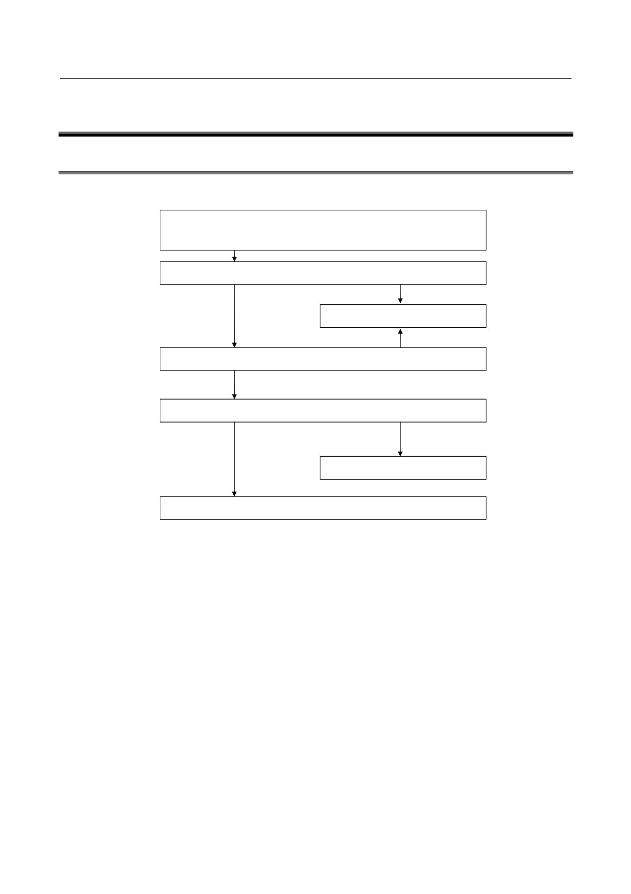
Check each item according to the procedure described below.
1.
Supply control power
(200 VAC) to the Power Supply at the
emergency stop state.
2. Check the STATUS LEDs. See Section 4.1.1.
Alarm occurs.
OK
See Section 3.1 of Part II.
Alarm occurs.
3. Release the system from emergency stop state.
4. Make sure that the MCC is turned on.
OK
NG
See Subsec. 4.1.4.
5. Check the operation of the servo and spindle motors.
- 13 -
4.CONFIRMATION OF THE
OPERATION
START-UP PROCEDURE
B-65285EN/04
4.1.1
Checking the Status LEDs (Power Supply)
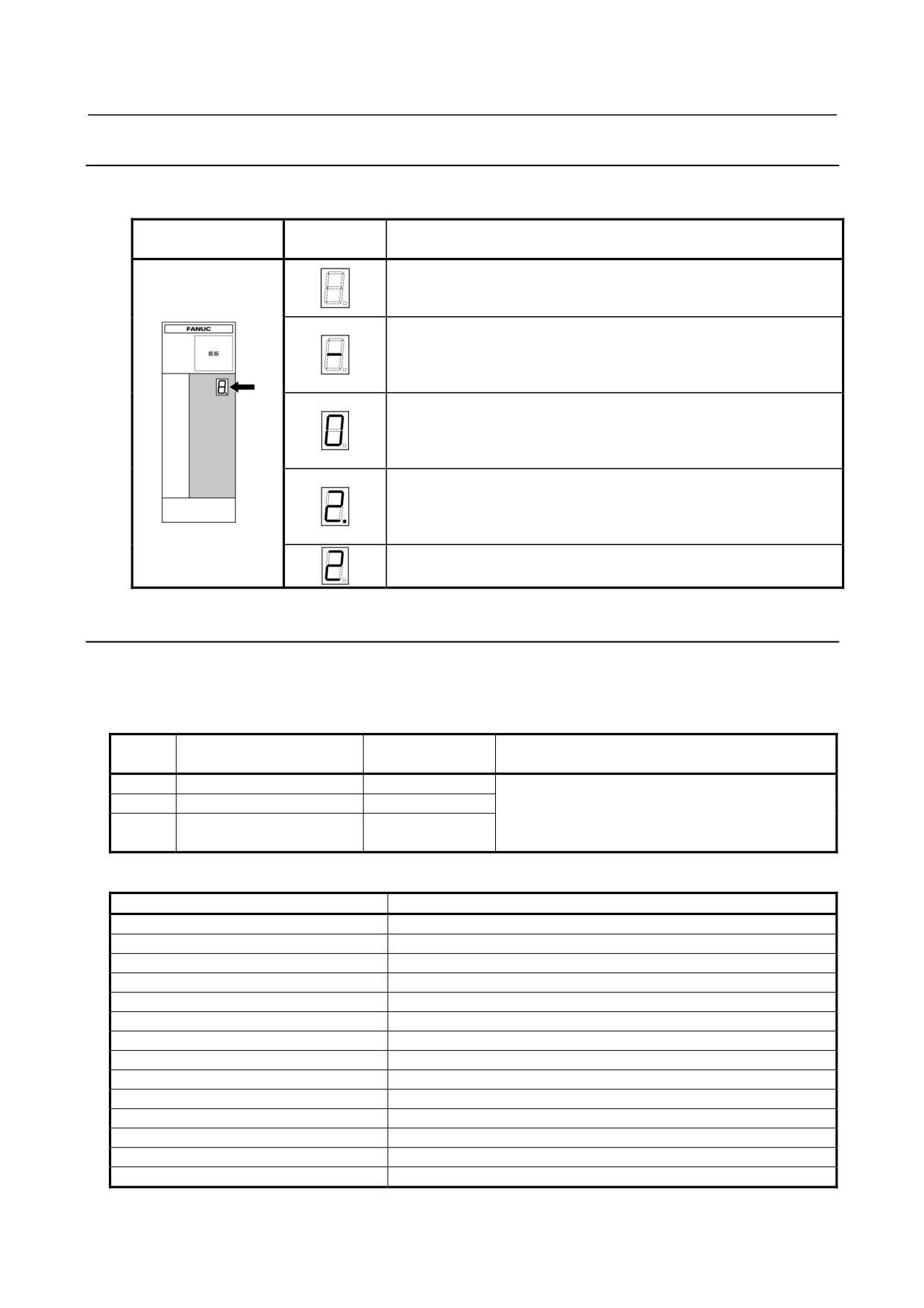
The STATUS display (a 7-segment LED) on the front of the Power Supply indicates the operation status.
STATUS
STATUS LED position
Description
display
The STATUS LED is off.
Control power has not been supplied, cable is faulty, or control power
circuit is defective.
Not ready status
The main circuit is not supplied with power (magnetic contactor is off);
emergency stop state.
When blinking: Power is off.
Ready status
The main circuit is supplied with power (magnetic contactor is on); the
power supply is ready for operation.
When blinking: Power is off.
Warning state (The dot at the lower right lights.)
The power supply has failed; an alarm has occurred after a certain
time of operation.
The warning type is indicated by the character displayed.
Alarm status
The alarm type is indicated by the character displayed.
4.1.2
Check Terminal on the Printed-circuit Board
To the Power Supply connector JX1B, the input current check signal is output. To observe the output, use
the servo check pin board A06B-6071-K290 (see below).
Table 4.1.2(a) Check pins
Check
Location of
Description
Remark
pin
observation
IR
L1 phase (R-phase) current
JX1B-pin1
The "+" sign with respect to the input of the amplifier.
IS
L2 phase (S-phase) current
JX1B-pin2
If the L1 or L2 phase current exceeds the overcurrent
Reference point of
alarm level, an alarm condition (with alarm code 01)
0V
JX1B-pin12,14,16
observation
occurs in the Power Supply.
Table 4.1.2 (b) IR and IS current conversion value
Model
Current conversion
αiPS 5.5
133A/1V(2.5 V at the center)
αiPS 11
133A/1V(2.5 V at the center)
αiPS 15
200A/1V(2.5 V at the center)
αiPS 26
266A/1V(2.5 V at the center)
αiPS 30
333A/1V(2.5 V at the center)
αiPS 37
400A/1V(2.5 V at the center)
αiPS 55
666A/1V(2.5 V at the center)
αiPS 11HV
100A/1V(2.5 V at the center)
αiPS 18HV
133A/1V(2.5 V at the center)
αiPS 30HV
200A/1V(2.5 V at the center)
αiPS 45HV
266A/1V(2.5 V at the center)
αiPS 60HV
333A/1V(2.5 V at the center)
αiPS 75HV
400A/1V(2.5 V at the center)
αiPS 100HV
466A/1V(2.5 V at the center)
- 14 -
4.CONFIRMATION OF THE
B-65285EN/04
START-UP PROCEDURE
OPERATION
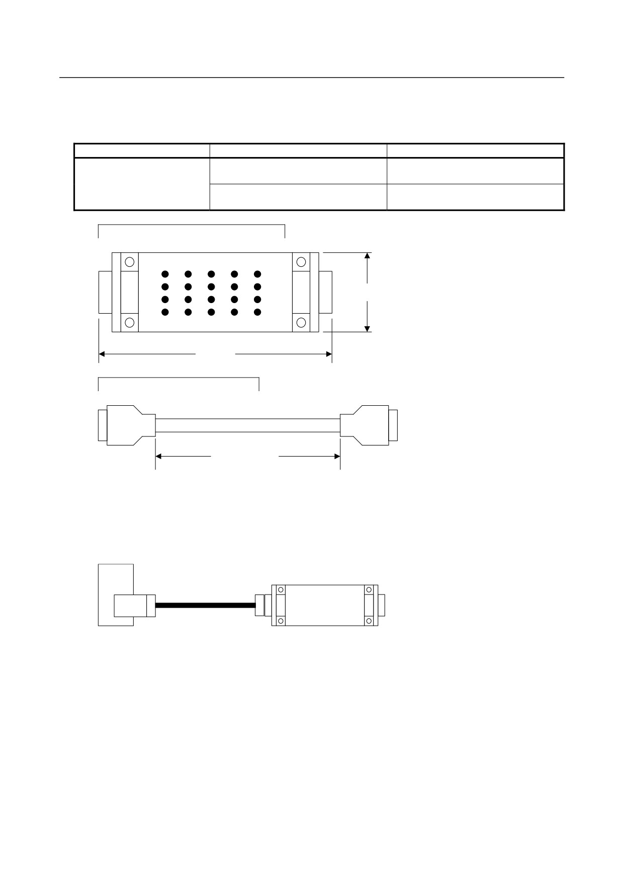
About the servo check pin board A06B-6071-K290
The servo check pin board can be used to observe signals in the Power Supply.
(1) Specification
Order specification
Description
Remark
Printed-circuit board
Printed-circuit board with check pins
A20B-1005-0340
mounted
A06B-6071-K290
Cable
20-conductor one-to-one cable
A660-2042-T031#L200R0
Length : 200mm
Printed-circuit board : A20B-1005-0340
A20B-1005-0340
<5>
<4>
<3>
<2>
<1>
<10>
<9>
<8>
<7>
<6>
34mm
<15>
<14>
<13>
<12>
<11>
<20>
<19>
<18>
<17>
<16>
CN1
CN2
100mm
Cable : A660-2042-T031#L200R0
Approx. 200mm
One-to-one wiring is provided between CN1 and CN2.
The connector pin numbers correspond to the check pin numbers.
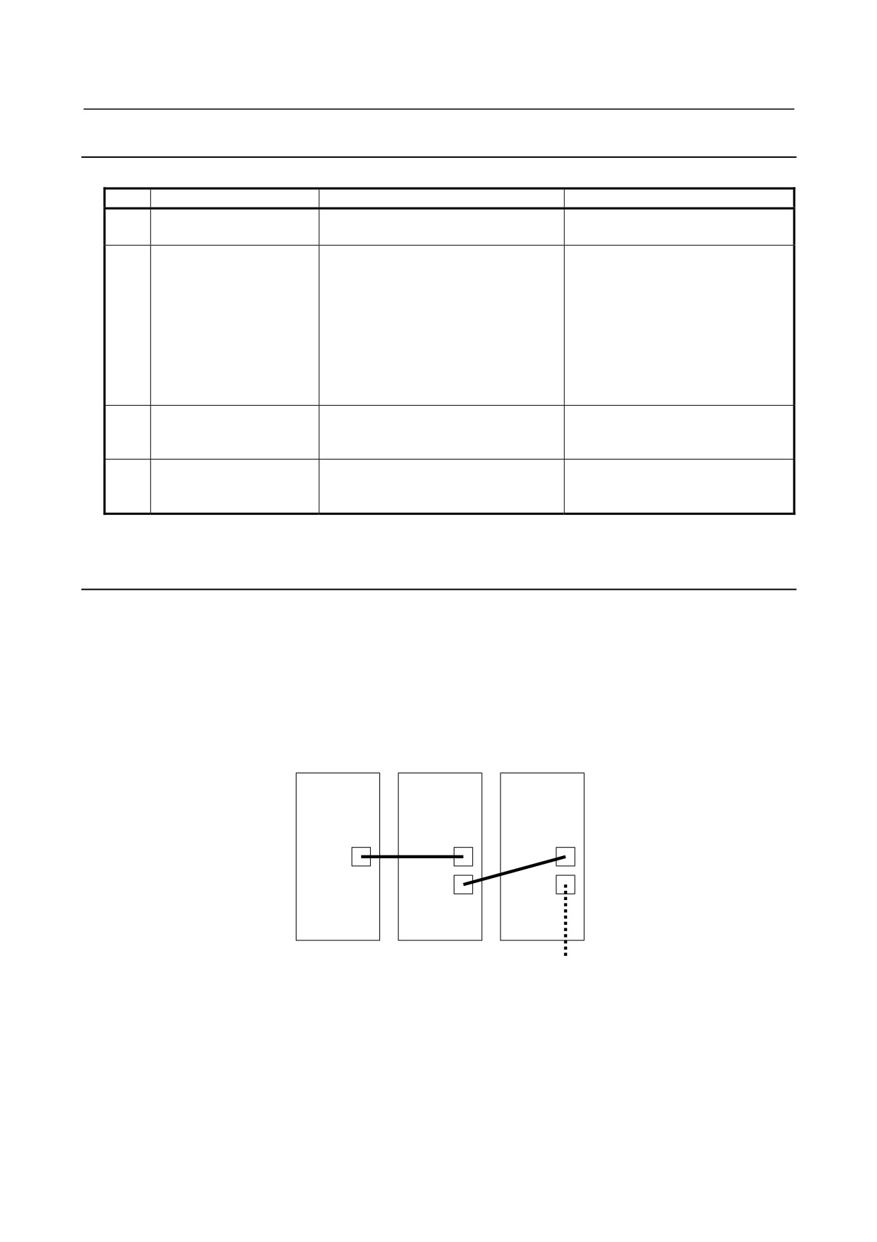
(2) Connection
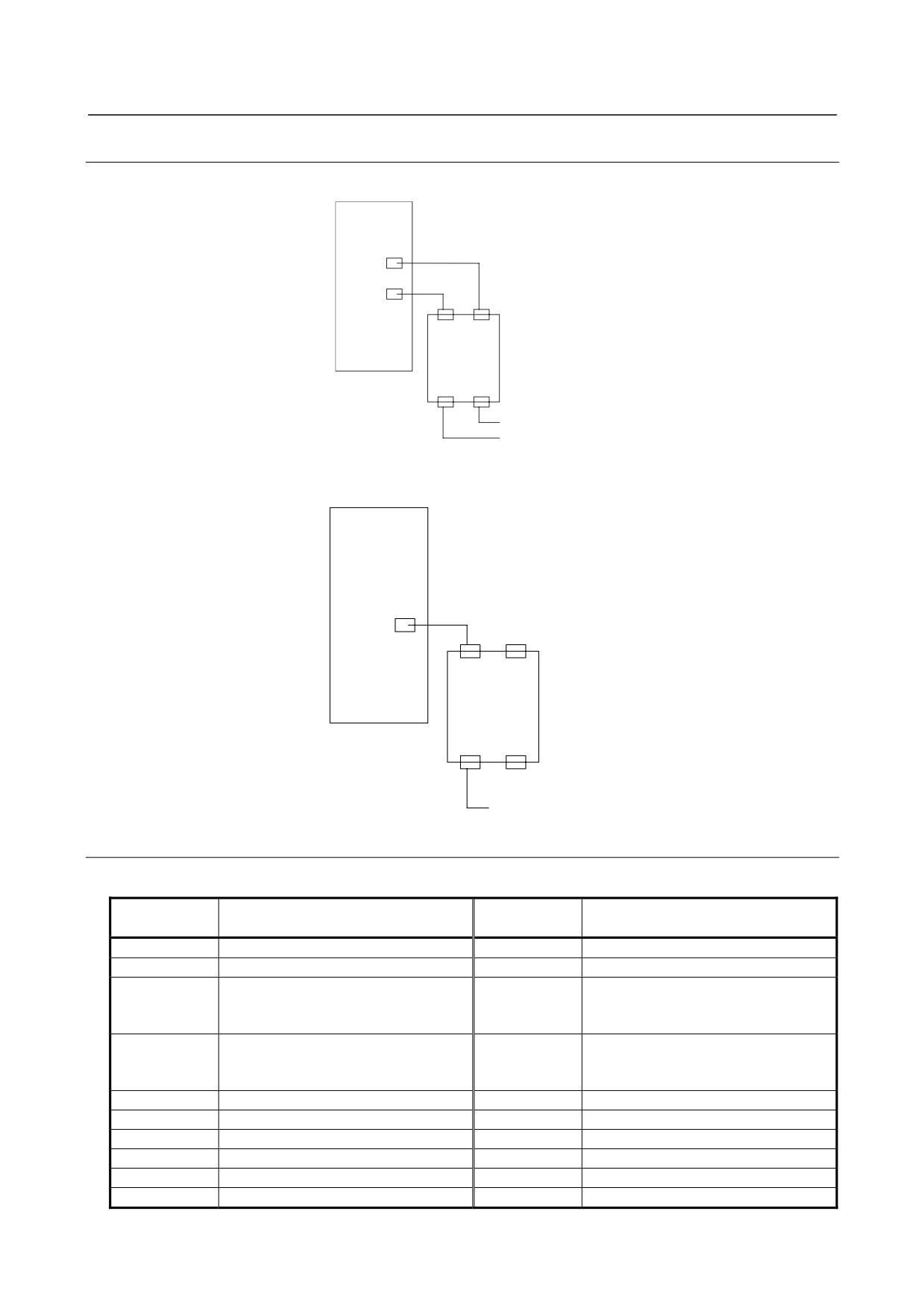
Connect the cable to the connector JX1B at the front of the Power Supply.
PS
A20B-1005-0340
JX1B
CN2
CN1
- 15 -
4.CONFIRMATION OF THE
OPERATION
START-UP PROCEDURE
B-65285EN/04
4.1.3
The PIL LED (Power ON Indicator) Is Off.
Table 4.1.3 Check method and action
No.
Cause of trouble
Check method
Action
AC power for the control
Check that power is connected to
1
circuit not supplied
connector CX1A.
(1) If the AC power input for control
is connected to connector CX1B
by mistake, F2 (FU2) may blow.
Connect the AC power input to
Blown fuse in the control
Check whether F1 or F2 has blown.
2
CX1A.
circuit
See Chapter 4 of Part II.
(2) Replace the fuse. If the fuse
blows again after the
replacement, replace the printed
circuit board.
Check whether the 24-V power output is
3
Incorrect wiring
short-circuited and whether a load
exceeding the rating is connected.
The power-on LED indicator PIL
Replace the printed circuit board,
Faulty power supply circuit
4
operates on the +5-V power supply.
driver board, or power distribution
on the printed circuit board
Check the control power voltage.
board.
4.1.4
Checking Method when Magnetic Contactor Is not Switched
On
(1) The system is still in an emergency stop status.
→ Check the connection.
(2) There is a connector problem. ("-" blinks for about 2 seconds or "P" is displayed after an emergency
stop status is released.)
(a) Check that the connectors are attached to correct locations.
→ Ensure that the connectors are attached to the location CXA2A on the Power Supply and the
location CXA2B on the Spindle Amplifier/Servo Amplifier.
PS
SP/SV
SP/SV
CXA2A
CXA2B
CXA2B
CXA2A
CXA2A
(Battery box for Pulsecoder)
(b) The interface cable between CXA2B of the Power Supply and CXA2A of the Servo Amplifier or
Spindle Amplifier is defective.
→ Check whether the interface cable is faulty.
(3) The power for driving the magnetic contactor is not supplied. ("-" blinks for about 2 seconds after an
emergency stop status is released.)
→ Check the voltage across the both ends of the coil of the magnetic contactor.
- 16 -
4.CONFIRMATION OF THE
B-65285EN/04
START-UP PROCEDURE
OPERATION
(4) The relay for driving the magnetic contactor is defective. ("-" blinks for about 2 seconds after an
emergency stop status is released.)
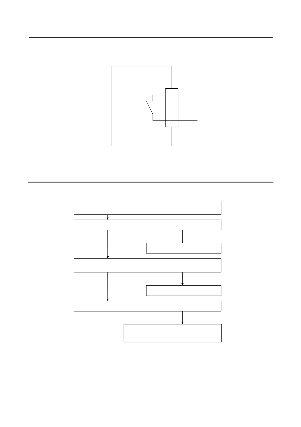
→ Check that a circuit between pins CX3-1 and CX3-3 of connector is closed and opened.
PS
CX3-1
MCC driving relay
CX3-3
(5) The Power Supply, Servo Amplifier, or Spindle Amplifier is defective.
→ Replace the defective module.
4.2
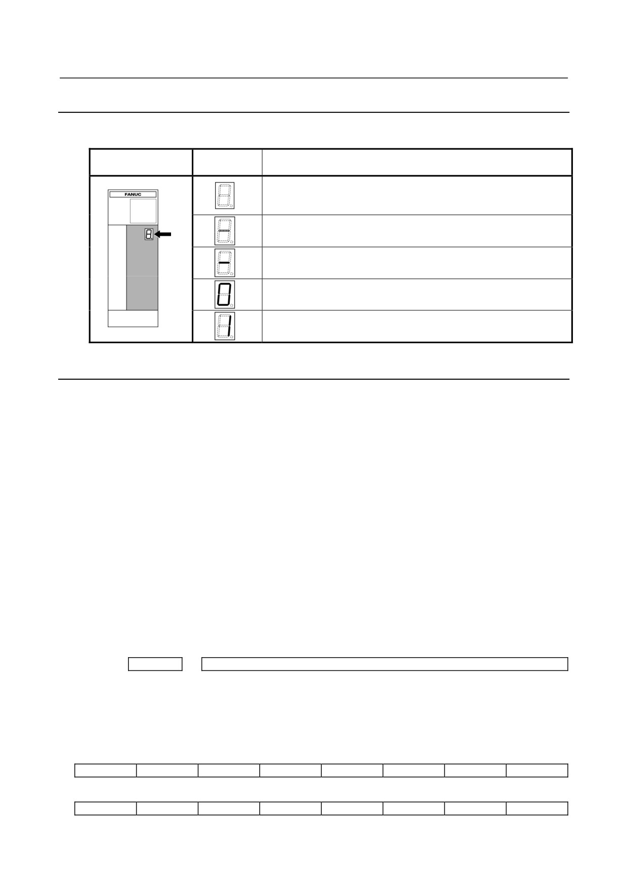
SERVO AMPLIFIER
Check each item according to the procedure described below.
1. Check the connection, and supply control power (200 VAC) to the
Power Supply.
2. Check the STATUS LEDs. See Section 4.2.1.
Alarm occurs.
See Section 3.2 of Part II.
3. Check the CNC parameters (including servo parameters), and reset
emergency stop state.
Alarm occurs.
See Section 3.2 of Part II.
4. Check the operation of the servo motor.
Abnormal operation
Refer to the FANUC AC SERVO MOTOR
αis/αi series Parameter Manual (B-65270EN).
- 17 -
4.CONFIRMATION OF THE
OPERATION
START-UP PROCEDURE
B-65285EN/04
4.2.1
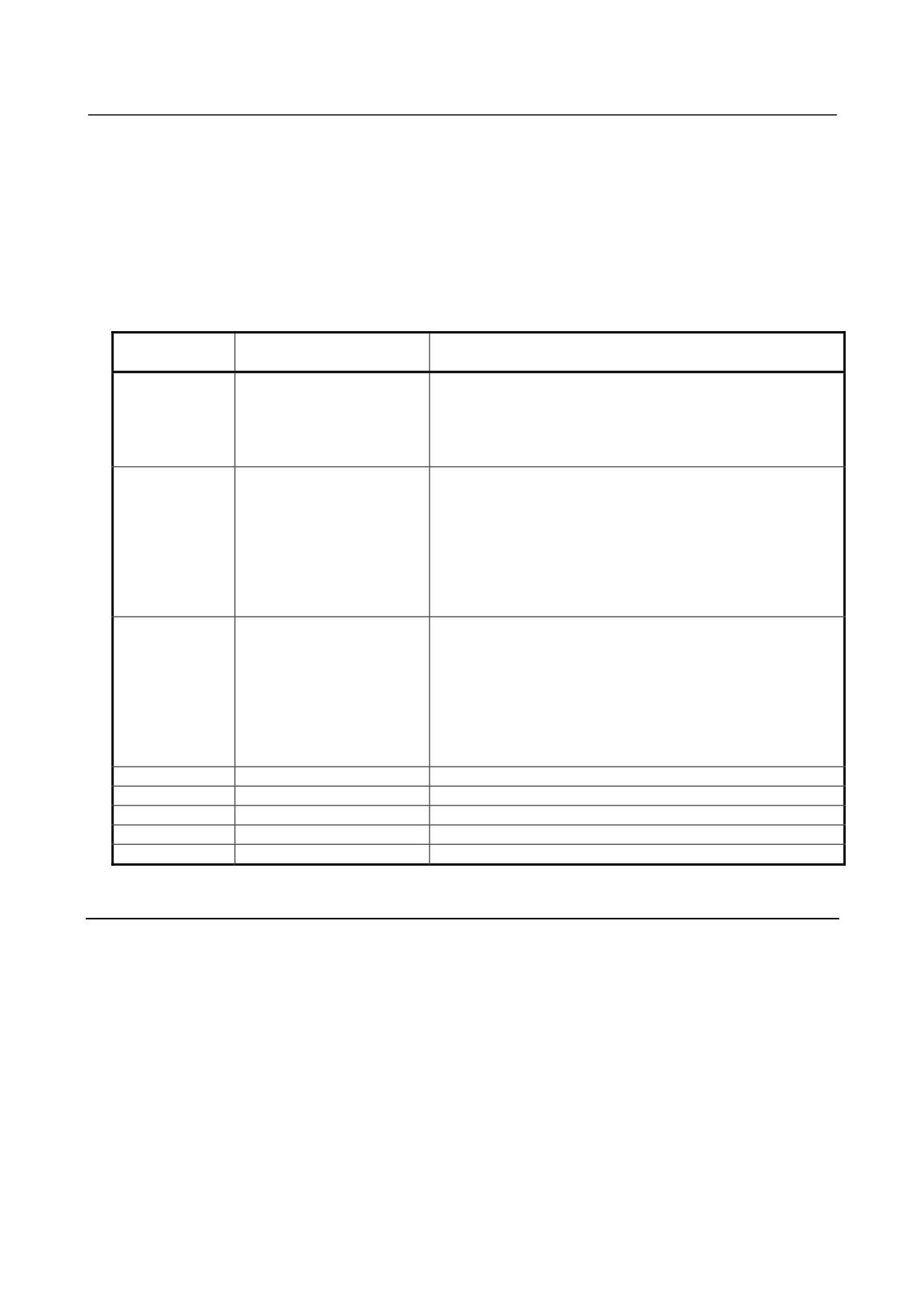
Checking the STATUS Display (Servo Amplifier)
The STATUS display (a 7-segment LED) on the front of the Servo Amplifier indicates the operation status.
STATUS LED
STATUS
Description
position
display
The STATUS LED is off.
Control power has not been supplied, cable is faulty, or control
Nameplate
power circuit is defective.
The control power is short-circuited (- blinks).
Blink
Cable failure
Waiting for the READY signal from the CNC.
Ready status
The servo motor is excited.
Alarm status
The alarm type is indicated by the character displayed.
4.2.2
VRDY-OFF Alarm Indicated on the CNC Screen
When the VRDY-OFF alarm is indicated on the CNC, check the items listed below. In addition,
VRDY-OFF can occur also for reasons other than listed below. If the following items turn out to have not
caused VRDY-OFF, check diagnosis information No. 358 (V ready-off information) on the diagnosis
screen and report it to FANUC.
(1) Communication interface between amplifiers
Is the cable for the communication interface (CXA2A/B) between the amplifiers connected correctly?
(2) Emergency stop signal (ESP)
Has the emergency stop signal (connector: CX4) applied to the Power Supply been released?
Alternatively, is the signal connected correctly?
(3) MCON signal
Hasn't setting up the axis detach function disabled the transmission of the ready command signal
MCON from the CNC to the Servo Amplifier?
(4) Servo Amplifier control printed-circuit board
The Servo Amplifier control printed-circuit board may be poorly installed or faulty. Be sure to push
the faceplate as far as it will go. If the problem persist, replace the control printed-circuit board.
On the Series 30i/31i/32i/16i/18i/21i/0i/PMi, checking diagnosis information (DGN) No. 358 makes it
possible to analyze the cause of the VRDY-OFF alarm.
Diagnosis
358
V ready-off information
Convert the displayed value to binary form, and check bits 5 to 14 of the resulting binary number.
When the servo amplifier starts working, these bits become 1 sequentially, starting at bit 5. When the servo
amplifier has started normally, all of bits 5 to 14 become 1.
Check bits 5 to 14 sequentially, starting at the lowest-order bit. The first lowest bit that is not 0 corresponds
to the processing that caused the V ready-off alarm.
#15
#14
#13
#12
#11
#10
#9
#8
SRDY
DRDY
INTL
RLY
CRDY
MCOFF
MCONA
#7
#6
#5
#4
#3
#2
#1
#0
MCONS
*ESP
HRDY
- 18 -
4.CONFIRMATION OF THE
B-65285EN/04
START-UP PROCEDURE
OPERATION
#06(*ESP) : Emergency stop signal
#07,#08,#09 : MCON signal (CNC → Servo Amplifier → Power Supply)
#10(CRDY) : Power Supply preparation completed signal
#11(RLY) : Relay signal (DB relay energized)
#12(INTL) : Interlock signal (DB relay de-energized)
#13(DRDY) : Amplifier preparation completed signal
The following table lists diagnosis information No. 358 values and main causes of problems. Do not insert
or remove any connector when the power is on.
Diagnosis No.
Problem
Check item
358 value
417
The system is still in an
(1) Check whether the emergency stop signal input to CX4 on
emergency stop state.
the Power Supply has been released.
(2) Check whether there is no problem with the connection or
cable for the communication interface between the amplifiers.
(3) Replace the Servo Amplifier.
993
The Power Supply
(1) Check whether there is no problem with the connection or
preparation completed signal
cable for the communication interface (CXA2A/B) between
(CRDY) is not output.
the amplifiers.
(2) Check whether the input power is supplied.
(3) Check whether the power is supplied to the operation coil of
the magnetic contactor. Check whether there is no problem
with the connection of CX3 on the Power Supply.
(4) Replace the Servo Amplifier.
4065
The interlock signal is not
When a dynamic brake module (DBM) is used, check (1) to (4).
input.
When no DBM is used, replace the Servo Amplifier.
(1) Check the connection between the Servo Amplifier and DBM.
(2) Check the connection between the Power Supply and Servo
Amplifier (CX1A/B).
(3) Check whether the fuse (FU2) on the control printed-circuit
board on the Power Supply has blown.
(4) Replace the Servo Amplifier.
225
-
Replace the Servo Amplifier.
481
-
Replace the Servo Amplifier.
2017
-
Replace the Servo Amplifier.
8161
-
Replace the Servo Amplifier.
97
-
Check whether the axis detach function is set.
4.2.3
Method for Observing Motor Current
This subsection explains how to observe the current that flows through the servo motor.
(1) Method of using the SERVO GUIDE
Refer to online help for explanations about how to connect to and use the servo adjustment tool, SERVO
GUIDE.
- Supported CNC systems
Series 30i/ 31i/32i -MODEL A (applied to 3.00 and subsequent editions of the SERVO GUIDE)
Series 16i/18i/21i -MODEL B
Series 0i-MODEL B, C, D (Series 0i-MODELD applied to 6.00 and subsequent editions of the SERVO
GUIDE)
Power Mate i -MODEL D,H
Servo software supporting the αi series
- 19 -
4.CONFIRMATION OF THE
OPERATION
START-UP PROCEDURE
B-65285EN/04
90Dx/A(01) and subsequent editions, 90Ex/A(01) and subsequent editions, 90C5/A(01) and subsequent
editions, 90B1/A(01) and subsequent editions, 90B5/A(01) and subsequent editions, 90B6/A(01) and
subsequent editions, 90B0/L(12) and subsequent editions, 9096/C(03) and subsequent editions
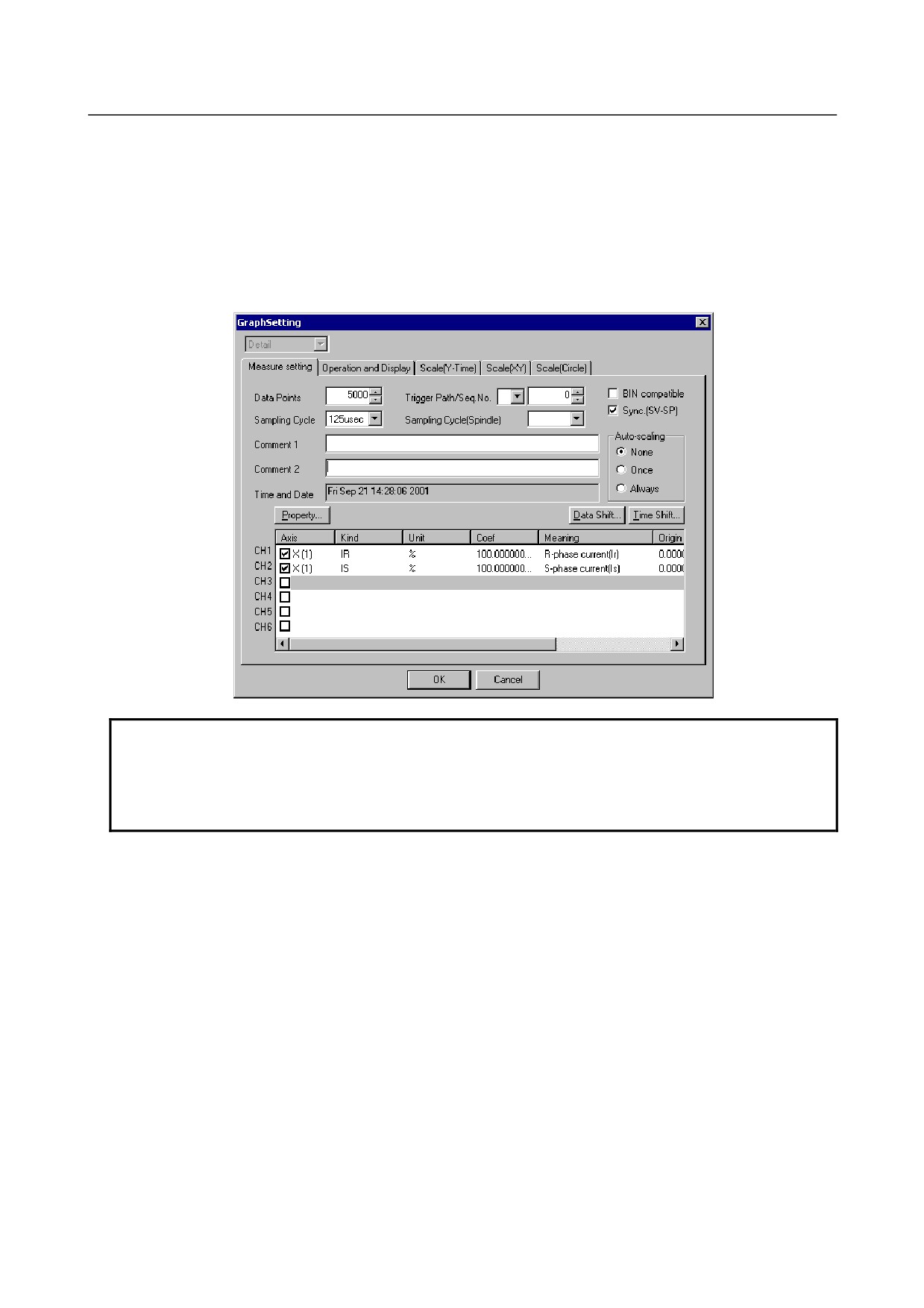
- Setting
Select an axis to be subjected to measurement in graph window channel setting. Also select IR and IS under
Kind. Under Coef (conversion coefficient), set the maximum allowable current (Ap) for the amplifier in
use.
NOTE
1 Servo software series 90B0 supports setting of a motor current sampling period of
up to 125 μs.
2 Servo software series 9096 supports setting of a motor current sampling period of
1 ms only.
- Display
Select the XTYT mode from the graph window mode (M) menu to display waveforms.
(2) Method of using the servo check board
For details on how to connect and use the servo check board, refer to the following:
Appendix I in the FANUC AC SERVO MOTOR αi series Parameter Manual (B-65270EN)
For Series 30i/31i/32i and Series 0i-MODEL C, D, use the SERVO GUIDE because the servo check board
cannot be connected and used.
- Required units
-
Servo check board
A06B-6057-H630
-
Oscilloscope
- 20 -
4.CONFIRMATION OF THE
B-65285EN/04
START-UP PROCEDURE
OPERATION
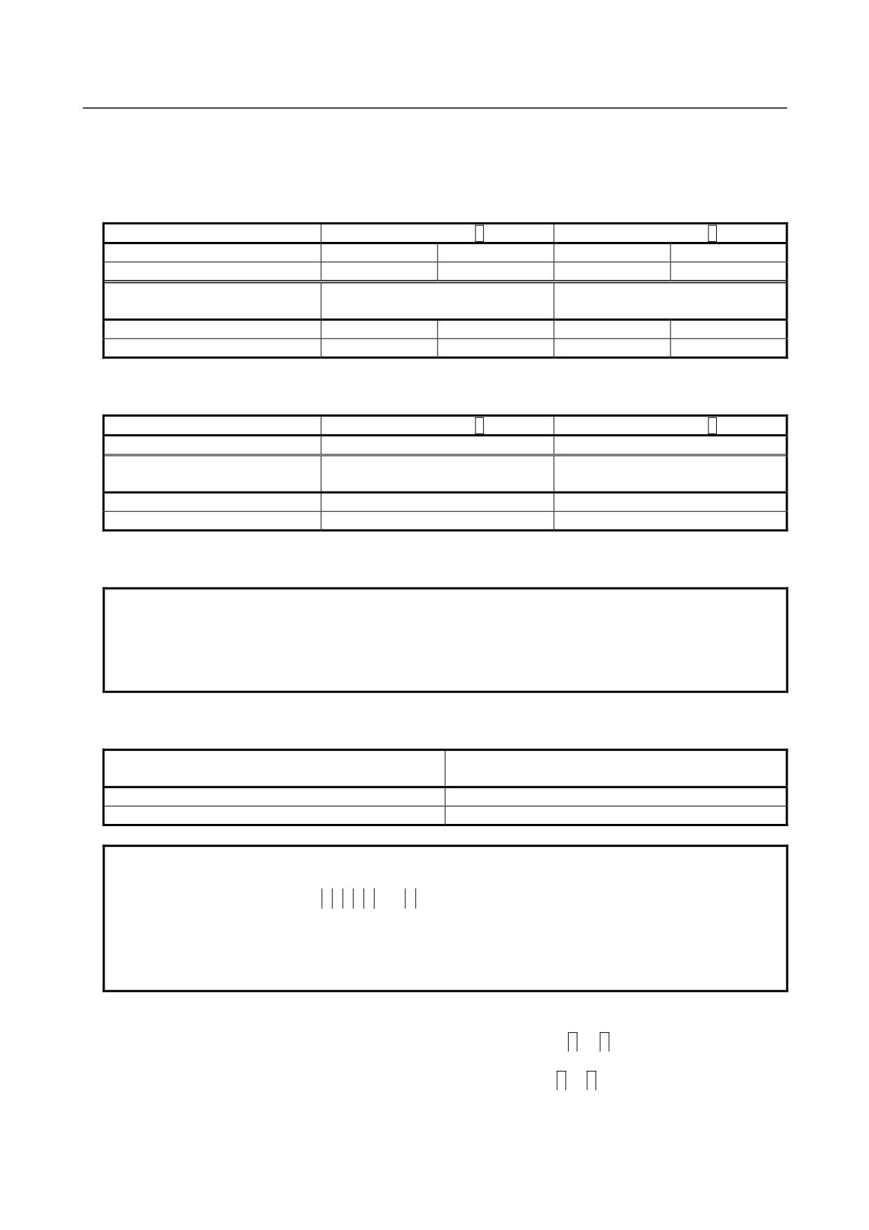
- Settings
⋅ CNC setting
Parameter setting for servo software series 90B0
Output channel
Data number
5
Data number
6
FS15i
No.1726
No.1774
No.1775
No.1776
FS16i/18i/21i/0i/PMi
No.2115
No.2151
No.2152
No.2153
Measurement axis/ current
IR
IS
phase
L-axis (Note 1)
370
0
402
0
M-axis (Note 1)
2418
0
2450
0
Parameter setting for servo software series 9096
Output channel
Data number
5
Data number
6
FS16i/18i/21i/0i/PMi
No.2115
No.2115
Measurement axis/ current
IR
IS
phase
L-axis (Note 1)
370
402
M-axis (Note 1)
1010
1042
When series 9096 is used, if no axis is paired with the measurement axis (Note 2), IR and IS cannot be
observed simultaneously.
NOTE
1 The L-axis is an axis identified with an odd number set in parameter No. 1023. The
M-axis is an axis identified with an even number set in parameter No. 1023.
2 The axis specified as 2n-1 in parameter No. 1023 and the axis specified as 2n will
be in a pair.
Setting the output period of motor current data (for the 90B0 series only)
Parameter No. 1746 /
Output period
Bit 7 of parameter No. 2206
Velocity loop period
0 (default)
Current loop period
1 (Note 3)
NOTE
3 If the current loop period is set up as the motor current data output period,
selecting data number
0,
1,
2, or
4 disables the output of signals (such as a
velocity command) to channels. To observe the motor current and other signals
(such as a velocity command), specify the output period as 1 ms.
4 For the servo software series 9096, the output period of the motor current is only 1
ms. The current loop period cannot be used for output.
⋅ Setting up the check board
-
Set the AXIS digit of the LED display with an axis number from
1
to
8
specified in parameter No.
1023.
-
Set the DATA digit of the LED display with a data number from
5
to
6
- 21 -
4.CONFIRMATION OF THE
OPERATION
START-UP PROCEDURE
B-65285EN/04
- Method for observing the motor current
The voltage corresponding to the motor current is output to a channel for which
5
or
6
is set as the data
number on the servo check board.
The waveform of the motor current can be observed by measuring the voltage mentioned above with an
oscilloscope.
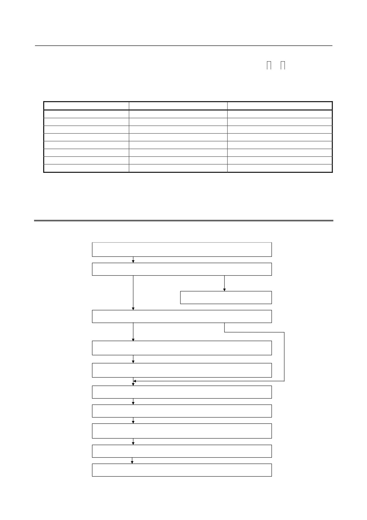
The following table lists the relationships between the observed voltage and the motor current.
Maximum amplifier current
Servo Amplifier type
Motor current/ observed voltage [A/V]
10A
αiSV 10HV and others
2.5
20A
αiSV 20 and others
5
40A
αiSV 40 and others
10
80A
αiSV 80 and others
20
160A
αiSV 160 and others
40
180A
αiSV 180HV and others
45
360A
αiSV 360 and others
90
540A
αiSV 540HV
135
For the Servo Amplifier1-20i, for example, the motor current is 5A (actual value rather than effective value)
if the observed voltage is 1V.
4.3
SPINDLE AMPLIFIER
Check each item according to the procedure described below.
1. Supply control power (200 VAC) to the Power Supply, and turn on
the power to the CNC.
2. Check the STATUS display. See Subsection 4.3.1.
OK
Alarm issued.
See Part II.
3. Has the system been used with this connection status?
No
Yes
4. Prepare and check a PMC ladder.
(The descriptions manual is
required.)
5. Set and check spindle-related parameters.
(The parameter manual
is required.)
6. Check the waveform on the sensor. See Subsection 4.3.4.
7. Release the system from the emergency stop state.
8. Make sure that the magnetic contactor for Power Supply input is
turned on. See Section 4.1.
9. Check the operation in normal operation mode (S command).
10. Check the operation of optional functions.
- 22 -
4.CONFIRMATION OF THE
B-65285EN/04
START-UP PROCEDURE
OPERATION
4.3.1
STATUS Display (Spindle Amplifier)
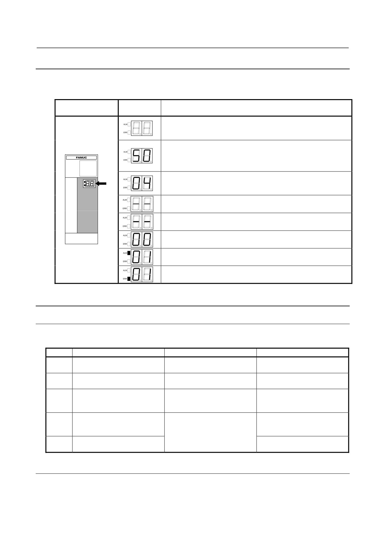
The STATUS display (a 7-segment LED) on the front of the Spindle Amplifier indicates the operation
status.
STATUS LED
STATUS
Description
position
display
The STATUS LED is off.
Control power has not been supplied, cable is faulty, or control
power circuit is defective.
After control power is turned on, the spindle software series is displayed
(for approx. 1 second).
The last two digits of the spindle software series number are
Nameplate
displayed.
The spindle software version is displayed (for approx. 1 second following
the display of the spindle software series).
[Display] 01,02,03,・・・
→ [Version] A, B, C,・・・
The CNC is not powered on (- - blinks).
Blink
Blink
Waiting for serial communication and parameter loading completion.
Parameter loading completed
The motor is not excited.
Ready status
The spindle motor is excited.
Alarm status
The alarm type is indicated by the character displayed.
Error status (invalid sequence or parameter setting error)
The error type is indicated by the character displayed.
4.3.2
Troubleshooting at Startup
4.3.2.1 The PIL LED (power-on indicator) is off.
(1) When the PIL LED on the spindle amplifiers does not come on after the main circuit breaker is turned
on
No.
Cause of trouble
Check method
Action
The 200-V control power is not
Check the cable attached to
1
The Power Supply PIL lamp is off.
supplied.
CX1A of Power Supply.
Check the cable attached to the
2
The cable is defective.
The Power Supply PIL lamp is on.
connector CXA2A/B.
The power is externally
When the connector is detached,
3
connected to 0 V, GND, or the
Replace or repair the cable.
the PIL lamp is on.
like.
If the fuse blows, the printed
There is a blown fuse on the
Even when all cables except the
4
circuit board may be faulty.
printed circuit board.
cable attached to connector
Replace the unit.
CX2A/B are detached, the PIL
The printed circuit board is
5
lamp does not come on.
Replace the unit.
defective.
4.3.2.2 The STATUS display is blinking with "--."
(1) When no spindle communication alarm message is indicated on the CNC
Check whether the CNC software option setting or bit setting is correct.
(2) When a communication alarm message is indicated on the CNC
- 23 -
4.CONFIRMATION OF THE
OPERATION
START-UP PROCEDURE
B-65285EN/04
No.
Cause of trouble
Check method
Action
Note that the cable used for
connecting an electric/optical
Replace the cable with a correct
1
The cable is incorrect.
adapter and the cable connected
cable.
directly to the CNC differ in
specifications.
Check the connector housing
2
The cable is defective.
Repair or replace the cable.
section.
The printed circuit board is
3
Replace the unit.
defective.
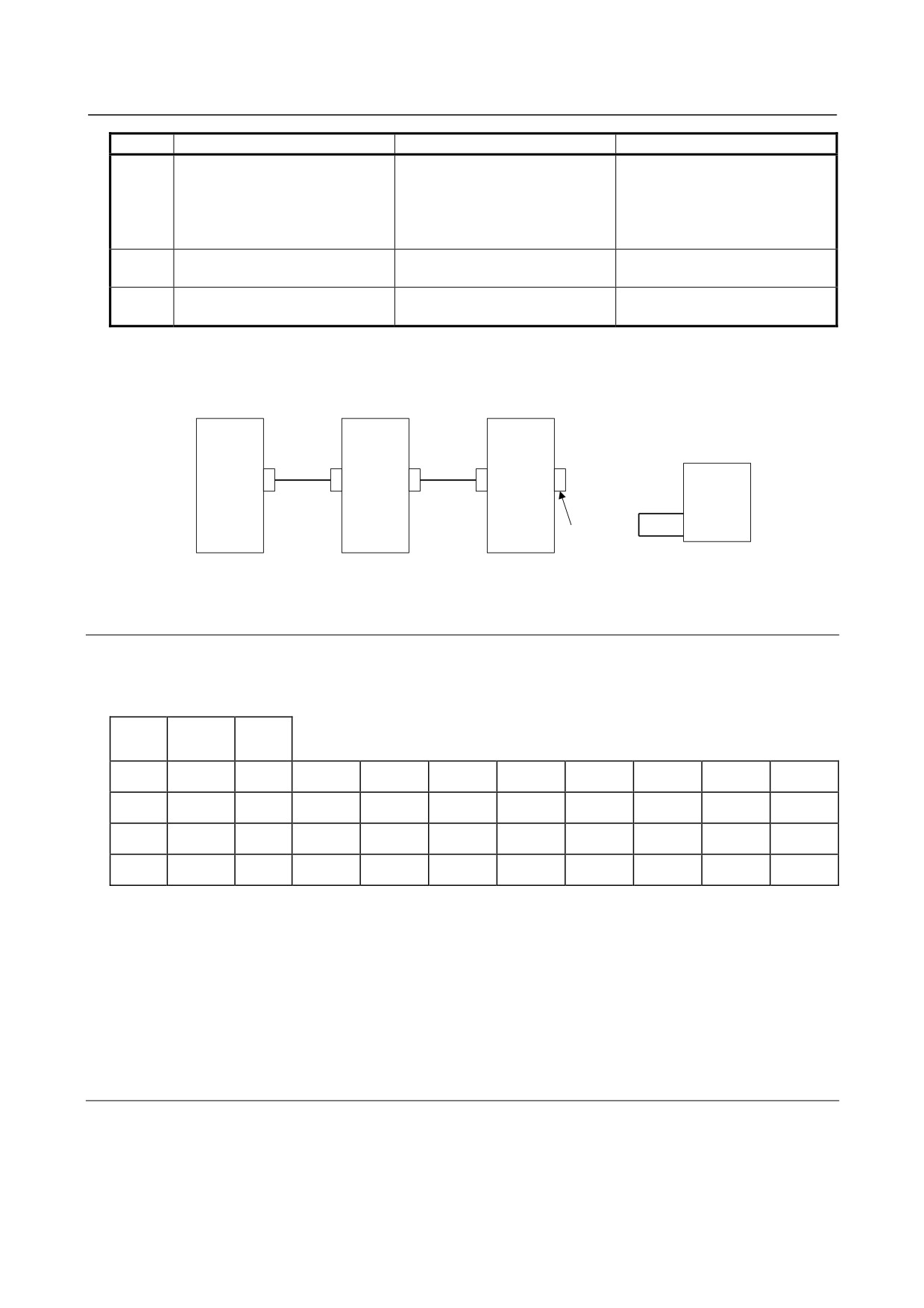
(3) When Dual Check Safety is in use, and No. 756 or 766 occurs on the CNC (FS16i)
Check that K76, shown below, is mounted on the second spindle.
If Dual Check Safety is not in use or the CNC has only the first spindle, K76 is unnecessary.
CNC
SP
SP
(First spindle)
(Second
Details of K76
spindle)
JA41 JA7B
JA7A JA7B
JA7A
K76
X2NDSP
(15)
0V
(13)
K76
20-pin half-pitch
connector
4.3.2.3 The motor does not turn.
(1) When "--" is indicated on the STATUS display of the Spindle Amplifier
Check whether spindle control signals are input. (An example for the first spindle is shown below.)
FS16i
FS30i
FS15i
FS0i-B/C
FS0i-D
#7
#6
#5
#4
#3
#2
#1
#0
G227
G070
G070
MRDYA
SFRA
SRVA
G226
G071
G071
*ESPA
-
G029
G029
*SSTP
-
G030
G030
SOV7
SOV6
SOV5
SOV4
SOV3
SOV2
SOV1
SOV0
(2) When "00" is indicated on the STATUS display of the Spindle Amplifier
No spindle speed command is input.
Refer to Chapter 1 in "FANUC AC SPINDLE MOTOR αi series Parameter Manual (B-65280EN),"
and check related parameters.
(3) When an alarm number is indicated on the Spindle Amplifier
See the description of the alarm number in Part II.
4.3.2.4 A specified speed cannot be obtained.
(1) When the speed always differs from a specified speed
Check parameters.
Refer to Chapter 1 in "FANUC AC SPINDLE MOTOR αi series Parameter Manual (B-65280EN),"
and check related parameters.
- 24 -

4.CONFIRMATION OF THE
B-65285EN/04
START-UP PROCEDURE
OPERATION
(2) When an alarm number is indicated on the Spindle Amplifier
See the description of the alarm number in Part II.
4.3.2.5 When cutting is not performed, the spindle vibrates, making
noise.
(1) The spindle vibrates only when the spindle speed has reached or is at a particular speed level.
Check whether the spindle also vibrates when the motor is turning by inertia. If noise is unchanged,
investigate the source of mechanical vibration. There are several methods to turn the spindle by inertia
as explained below. Because these methods involve machine sequences, consult with the machine tool
builder.
A. Setting spindle control signal MPOF (FS16i: G73#2, FS15i: G228#2) to 1 immediately causes
the spindle to turn by inertia.
B. Set ALSP (FS16i: bit 2 of parameter No. 4009, FS15i: bit 2 of parameter No. 3009) to 1. Then,
when the power to the CNC is turned off during spindle rotation, the spindle turns by inertia. (On
the spindle amplifier, Alarm 24 is indicated.)
(2) When noise is generated at the time the motor is stopped or at any time
A. See Subsection 4.3.4 of this part, and check and adjust the waveform of the spindle sensor.
B. Check that the motor part number matches its parameters. For details, refer to Appendix A in
"FANUC AC SPINDLE MOTOR αi series Parameter Manual (B-65280EN)."
C. Adjust the velocity loop gain and so forth.
For details, refer to Chapter 1 in "FANUC AC SPINDLE MOTOR αi series Parameter Manual
(B-65280EN)."
4.3.2.6 An overshoot or hunting occurs.
Refer to Chapter 1 in "FANUC AC SPINDLE MOTOR αi series Parameter Manual (B-65280EN)," and
adjust parameters.
4.3.2.7 Cutting power weakens or acceleration/deceleration slows
down.
(1) When the load meter does not indicate the maximum output
A. A mechanical cause such as a belt slip may occur.
(2) When the load meter indicates the maximum output
A. Check whether the torque limit signal is input incorrectly.
FS16i
FS30i
FS15i
FS0i-B/C
FS0i-D
#7
#6
#5
#4
#3
#2
#1
#0
G227
G070
G070
TLMHA
TLMLA
B. If you are using the αi BZ sensor, it is likely that a slip has occurred between the sensor gear and
spindle (on acceleration).
C. Check that the motor part number matches its parameters.
For details, refer to Appendix A in "FANUC AC SPINDLE MOTOR αi series Parameter Manual
(B-65280EN)."
D. Check whether the output limit pattern is set incorrectly.
For details, refer to Chapter 1 in "FANUC AC SPINDLE MOTOR αi series Parameter Manual
(B-65280EN)."
- 25 -
4.CONFIRMATION OF THE
OPERATION
START-UP PROCEDURE
B-65285EN/04
4.3.3
Status Error Indication Function
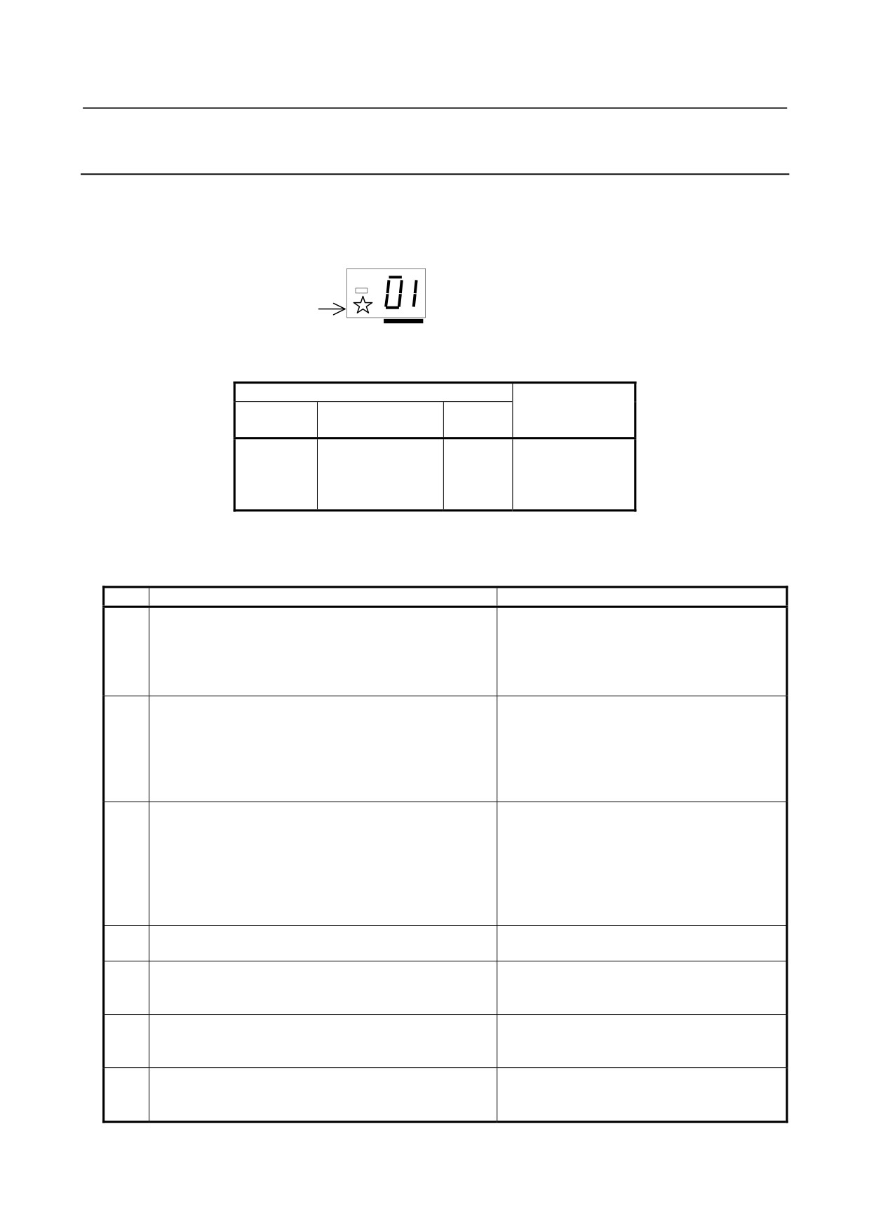
When there is a sequence or parameter error, the error LED (yellow) in the display section of the Spindle
Amplifier (SP) goes on with an error code displayed. This can ease troubleshooting at the time of machine
startup.
Status
The error LED
(yellow) lights.
An error code is indicated. (from 01)
The error code is also displayed on the CNC diagnosis screen.
Diagnosis No.
FS30i
Description
FS15i
FS16i
FS0i-D
710(First spindle)
711(Second spindle)
1561
710
Status error code
730(Third spindle)
731(Fourth spindle)
When the Spindle Amplifier does not operate for a certain function, check whether the status error is
indicated in the display section of the Spindle Amplifier or CNC diagnosis screen.
No.
Description
Action
Although neither *ESP (emergency stop signal) (there are
Check the *ESP and MRDY sequences. For
two types of signals, a PMC signal and Power Supply (PS)
MRDY, pay attention to the parameter that
01
contact signal) nor MRDY (machine ready signal) has
specifies whether to use the MRDY signal (bit 0
been input, SFR (forward rotation signal), SRV (reverse
of parameter No. 4001).
rotation signal), or ORCM (orientation command) is input.
Although parameter settings are such that that there is no
position sensor (position control is not to be performed,
that is, bits 3, 2, 1, and 0 of parameter No. 4002 are,
03
Check setting of the parameter.
respectively, 0, 0, 0, and 0), a Cs axis contour control
command has been issued.
In this case, the motor is not activated.
Although parameter settings are such that that there is no
position sensor (position control is not to be performed,
that is, bits 3, 2, 1, and 0 of parameter No. 4002 are,
04
respectively, 0, 0, 0, and 0), a servo mode (such as rigid
Check setting of the parameter.
tapping or Cs axis control) command or spindle
synchronization control command has been issued.
In this case, the motor is not activated.
Although optional parameter for the orientation function is
05
Check setting of the parameter for orientation.
not set, an ORCM (orientation command) is input.
Check setting of the parameter for output
Although optional parameter for the output switching
06
switching and the power line status signal
option is not set, low-speed winding is selected (RCH = 1).
(RCH).
Although Cs contour control mode is input, neither SFR
07
(forward rotation signal) nor SRV (reverse rotation signal)
Check the sequence.
is input.
Although servo mode (rigid tapping or spindle positioning)
08
control command is input, neither SFR (forward rotation
Check the sequence.
signal) nor SRV (reverse rotation signal) is input.
- 26 -
4.CONFIRMATION OF THE
B-65285EN/04
START-UP PROCEDURE
OPERATION
No.
Description
Action
Although spindle synchronization control command is
09
input, neither SFR (forward rotation signal) nor SRV
Check the sequence.
(reverse rotation signal) is input.
Do not specify another mode during execution
Although Cs contour control command is input, another
of the Cs contour control command. Before
10
operation mode (servo mode, spindle synchronization, or
entering another mode, cancel the Cs contour
orientation) is specified.
control command.
Although servo mode (rigid tapping or spindle positioning)
Do not specify another mode during execution
11
is input, another operation mode (Cs contour control,
of the servo mode command. Before entering
spindle synchronization, or orientation) is specified.
another mode, cancel servo mode.
Do not specify another mode during execution
Although spindle synchronization is input, another
of the spindle synchronization command.
12
operation mode (Cs contour control, servo mode, or
Before entering another mode, cancel the
orientation) is specified.
spindle synchronization command.
Although orientation specification is input, another
Do not specify another mode during execution
13
operation mode (Cs contour control, servo mode, or
of the orientation command. Before entering
synchronization control) is specified.
another mode, cancel the orientation command.
The SFR (forward rotation signal) and SRV (reverse
14
Input one of the SFR and SRV signals.
rotation signal) are input at the same time.
Although the parameter not to use the differential speed
Check the setting of the parameter and the
16
control function (bit 5 of parameter No. 4000 = 0) is set,
differential speed mode command.
DEFMD (differential speed mode command) is input.
The parameter settings for the speed detector (bits 2, 1,
17
and 0 of parameter No. 4011) are invalid. There is no
Check the setting of the parameter.
speed detector that matches the settings.
Although parameter settings are such that that there is no
position sensor (position control is not to be performed,
Check the setting of the parameter and the input
18
that is, "bits 3, 2, 1, and 0 of parameter No. 4002 are,
signal.
respectively, 0, 0, 0, and 0," a position coder-based
orientation command has been issued.
Although magnetic sensor orientation command is input,
Do not specify another mode during execution
19
another operation mode (Cs contour control, servo mode,
of the orientation command. Before entering
or spindle synchronization) is specified.
another mode, cancel the orientation command.
The tandem operation command was input in the spindle
Input the tandem operation command when
21
synchronization control enable state.
spindle synchronization control is canceled.
Spindle synchronization control was specified in the
Specify spindle synchronization control when
22
tandem operation enable state.
torque tandem operation is canceled.
The tandem operation command is input without the
Torque tandem control requires a CNC software
23
required option.
option. Check the option.
Although continuous indexing in position coder-based
Check the INCMD (incremental command).
orientation is to be performed, an absolute position
Be sure to perform absolute position
24
command (INCMD = 0) has been issued after incremental
command-based orientation before an absolute
operation (INCMD = 1).
position command.
The parameter settings are such that both spindle switch
Check the parameter settings and the input
26
and three-stage speed range switch are used.
signal.
The shortest-time orientation function cannot be
Parameter settings are such that the shortest-time
used in the αi series spindle amplifier. The use
29
orientation function is to be used (bit 6 of parameter No.
of the optimum orientation function is
4018 is 0 and parameter Nos. 4320 to 4323 are nonzero).
recommended.
- 27 -
4.CONFIRMATION OF THE
OPERATION
START-UP PROCEDURE
B-65285EN/04
No.
Description
Action
The magnetic pole has not been detected, but a command
In the magnetic pole undetected state (EPFIXA
is input.
= 0), the motor cannot be driven even when a
command is input. Input a command in the
magnetic pole detected state (EPFIXA = 1).
30
When EPFSTR is set to 1, any command is
ignored and this error is displayed even in the
magnetic pole detected state. After the
completion of magnetic pole detection, set
EPFSTR to 0.
This hardware configuration does not support the use of
31
the spindle FAD function. In this case, the motor is not
Check the CNC model.
activated.
S0 is not specified in the velocity mode, but the
Specify S0 in the velocity mode before enabling
32
disturbance input function is enabled (bit 7 of parameter
the disturbance input function (bit 7 of
No. 4395 is set to 1).
parameter No. 4395 to 1).
This hardware configuration does not support the use of
33
the spindle EGB function. In this case, the motor is not
Check the CNC model.
activated.
Both spindle FAD function and spindle EGB function are
These functions cannot be used at the same
34
enabled. In this case, the motor is not activated.
time. Enable only one of the functions.
Spindle Amplifier (SP) ID information cannot be obtained.
Replace the spindle amplifier with one with
35
correct ID information.
The submodule SM (SSM) is faulty .
For the action to be taken for this status error,
1) The interface signal between the Spindle Amplifier
refer to Section 1.4, "Submodule SM," in Part IV
36
and SSM is disconnected.
in the FANUC AC SPINDLE MOTOR αi series
2) SSM failure
Parameter Manual.
The current loop setting (No. 4012) has been changed.
Check the setting of parameter No. 4012, and
37
turn the power off, then on again.
A parameter related to communication between spindle
Check the parameters.
38
amplifiers is specified incorrectly. Alternatively, a function
unavailable with the torque tandem function is set.
Although SFR (forward rotation command), SRV (reverse
Check the sequence. Do not input DSCN
rotation command), or ORCM (orientation command) is
(disconnection detection disable signal) during
39
input, DSCN (disconnection detection disable signal) is
the input of a command which excites the motor.
input.
A setting which does not support the αiCZ sensor (serial)
Check the parameter settings.
43
is used.
The spindle amplifier does not support the control period
Check the setting of parameter No. 4012.
44
setting.
- 28 -
4.CONFIRMATION OF THE
B-65285EN/04
START-UP PROCEDURE
OPERATION
NOTE
*1 When status error 43 is displayed, check the following items. The items to be
checked differ depending on the series and edition of the spindle software.
Series 9D80 edition E (edition 05) or edition F (edition 06): Items <1> to <12>
Series 9D80 edition G (edition 07): Items <1> to <9>, <12>, and <13>
Series 9D80 edition H (edition 08): Items <1> to <9>, <13>, and <14>
(1) For both the motor sensor and spindle sensor, the setting is made to use an
αiCZ sensor (serial). (No.4010#2,1,0=0,1,0 and No.4002#3,2,1,0=0,1,1,0)
(2) Spindle HRV control is not set. (No.4012#7=0)
(3) The setting is made to use the differential speed control function.
(No.4000#5=1)
(4) The setting is made to use the spindle switch control function.
(No.4014#0=1)
(5) The setting is made so that an alarm related to position feedback is not
detected. (No.4007#6=1 or No.4016#5=0)
(6) The setting is made so that the disconnection of the feedback signal is not
detected. (No.4007#5=1)
(7) The setting is made so that an alarm related to position signal feedback is not
detected during thread cutting. (No.4016#5=0)
(8) The setting is made to use an external one-rotation signal. (No.4004#2=1)
(9) The setting is made to use a position coder. (No.4002#3,2,1,0=0,0,1,0)
(10) The setting is made to drive a synchronous spindle motor. (No.4012#6=1)
(11) The setting is made to use communication between Spindle Amplifiers.
(No.4352#7=1 or No.4352#6=1)
(12) The setting is made to use the Dual Check Safety function.
(13) The setting is made to use the spindle tandem function. (No.4015#3=1)
(14) Although the setting is made to use an αiCZ sensor (serial) as the motor
sensor, the Dual Check Safety function is enabled.
4.3.4
Checking the Feedback Signal Waveform
The measurement locations and the method for attaching connectors vary depending on the configuration of
the detector. Check the waveform while seeing Table 4.3.4. The check terminals are on the check board.
Table 4.3.4(a) Signals input to the Spindle Amplifier and corresponding check terminals on the check board
Check
Spindle Amplifier input
terminal
signal (connector
Main sensors
Remarks
name
name-pin No.)
PA1
JYA2-pin5,6
αi M, αi MZ, and αi BZ sensors
PB1
JYA2-pin7,8
Analog αi CZ sensor
αi BZ sensor
PA2
JYA4-pin5,6
Analog αi CZ sensor
For TYPE B only
PB2
JYA4-pin7,8
α position coder S(1024λ)
αi MZ and αi BZ sensors (one-rotation signal)
PS1
JYA2-pin1,2
Analog αi CZ sensor (one-rotation signal)
αi BZ sensor (one-rotation signal)
PS2
JYA4-pin1,2
For TYPE B only
Analog αi CZ sensor (one-rotation signal)
EXTSC1
JYA3-pin15
Proximity switch (external one-rotation signal)
For the α position coder and α position coder S (one-rotation signal), observe the Spindle Amplifier input
signal directly, using the servo check pin board A06B-6071-K290.
- 29 -
4.CONFIRMATION OF THE
OPERATION
START-UP PROCEDURE
B-65285EN/04
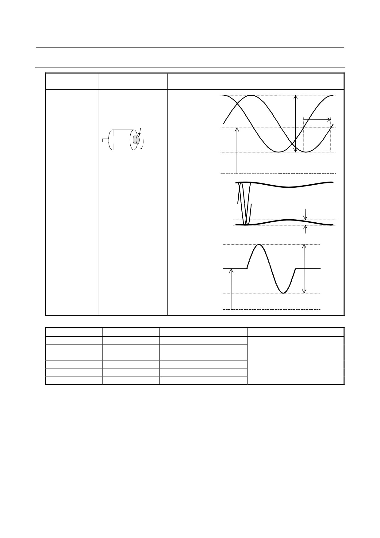
4.3.4.1 αi M sensor, αi MZ sensor, and αi BZ sensor
Measurement
Measurement
Sample waveform
location
condition
PA1, PB1
The speed must be 1500
Waveforms of phase
min-1 or less.
Vpp
A and phase B
PA1 (PA2)
Separate sensors
PA2, PB2
Rotation direction: CW
Detection gear
Vphase
Voffs
PB1 (PB2)
Motor
CW
0 V
Ripples of phase A and
phase B
PA1, PB1 (PA2, PB2)
Vrip
For αi MZ and αi BZ sensors only
PS1
Waveform of
phase Z
(Z - *Z)
Separate sensor
Vpz
PS2
Voffz
0 V
Measurement item
Specification
Measurement method
Adjustment method
Vpp
0.5 to 1.2 Vp-p
Normally, the αi M and αi MZ
Use the DC range of a digital
Voffs, Voffsz
2.5 V ±100 mV
sensors need not be adjusted. For
voltmeter.
Voffs and Voffz, only level check is
Vphase
90 ±3°
possible, but adjustment is not
Vrip
< 70 mV
possible.
Vpz
> 0.5 V
- 30 -
4.CONFIRMATION OF THE
B-65285EN/04
START-UP PROCEDURE
OPERATION
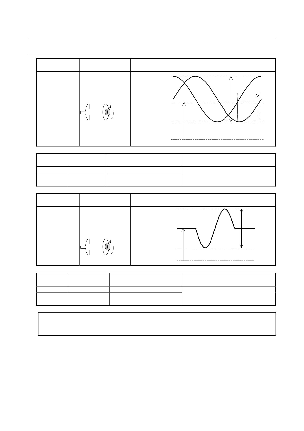
4.3.4.2 Analog αi CZ sensor
Measurement
Measurement
Sample waveform
location
condition
PA1, PB1
Speed: 500min-1
Waveforms of phase
Vpp
A and phase B
PA1(PA2)
Separate sensors
PA2, PB2
Rotation direction: CW
Detection gear
Vphase
Voffs
PB1(PB2)
Motor
CW
0V
Measureme
Specification
Measurement method
Adjustment method
nt item
Vpp
0.9 to 1.1V p-p
The sensors are adjusted at shipment.
Use the DC range of a digital
Do not adjust the sensors, or the detection
Voffs
2.5V ± 50mV
voltmeter.
precision is affected.
Measurement
Measurement
Sample waveform
location
condition
PS1
Speed: 500min-1
Waveform of
Separate sensor
phase Z
Z
Vpz
PS2
Rotation direction: CW
Detection gear
Voffz
Motor
CW
0V
Measureme
Specification
Measurement method
Adjustment method
nt item
Vpz
0.66 to 1.65V p-p
The sensors are adjusted at shipment.
Use the DC range of a digital
Do not adjust the sensors, or the detection
Voffsz
2.5V ± 50mV
voltmeter.
precision is affected.
NOTE
For how to check the serial output αiCZ sensor signals, refer to the technical
report of the relevant sensor.
- 31 -
4.CONFIRMATION OF THE
OPERATION
START-UP PROCEDURE
B-65285EN/04
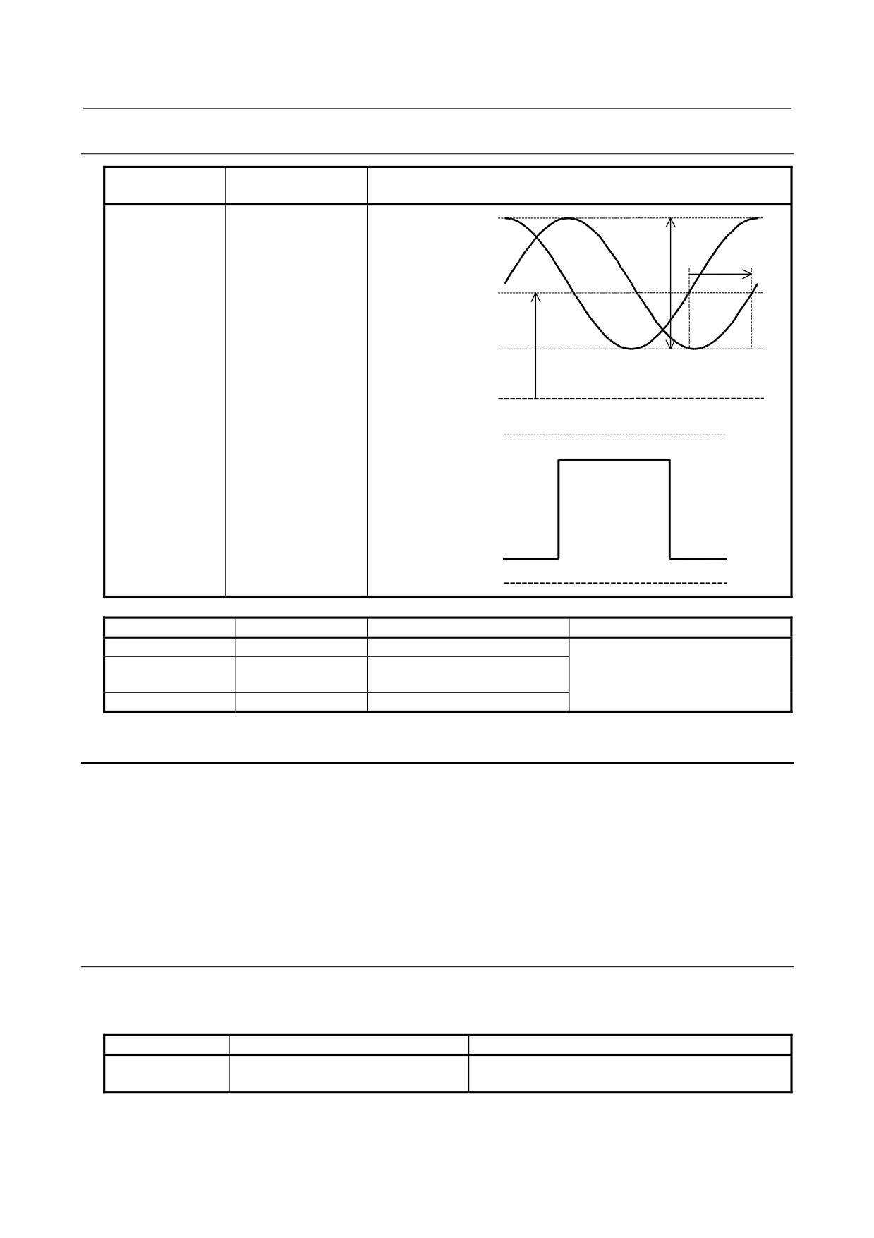
4.3.4.3 α position coder S
Measurement
Measurement
Sample waveform
location
condition
PA2, PB2
CW rotation direction
Waveforms of phase
as viewed from the
Vpp
A and phase B
PA1 (PA2)
flange
Vphase
Voffs
PB1 (PB2)
0 V
Waveform of phase
Z
(Z - *Z)
0V
Measurement item
Specification
Measurement method
Adjustment method
Vpp
0.8 to 1.2 Vp-p
Use the DC range of a digital
Only level check is possible, but
Voffs,Voffsz
2.5 V ±100 mV
voltmeter.
adjustment is not possible.
Vphase
90 ±5°
4.3.5
Spindle Check Board
When connecting the check board, you can:
<1> Observe signal waveforms.
<2> Observe internal data.
<3> Check spindle parameter values.
You can perform the above more easily by using the SERVO GUIDE. For information about the SERVO
GUIDE, see Subsection 4.3.8.
4.3.5.1 Spindle check board specifications
Spindle check board specifications is bellow.
Table 4.3.5.1 Spindle check board specifications
Specification
Drawing No. of printed circuit board
Applicable unit
αi series, αCi series
A06B-6078-H001
A20B-2001-0830
(having the same specification as for the α series)
- 32 -
4.CONFIRMATION OF THE
B-65285EN/04
START-UP PROCEDURE
OPERATION
4.3.5.2 Check board connection
(1) αi series
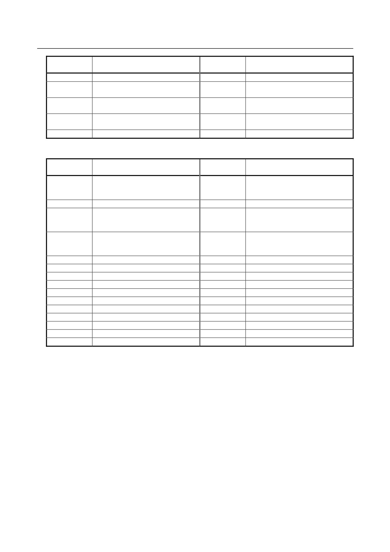
SP
JX4
JY1
JY1A JX4ASpindle check
board
A20B-2001-0830
JY1B JX4B
Output equivalent to JX4
Output equivalent to JY1
(2) αCi series
SPMC
JY1
Spindle
JY1A JX4A
check
board
A20B-2001-0830
JY1B JX4B
Output equivalent to JY1
4.3.5.3 Check terminal output signals
(1) αi series
Check
Check
Signal name
Signal name
terminal
terminal
LM
Load meter signal
PA1
Phase A sine wave signal 1
SM
Speedometer signal
PB1
Phase B sine wave signal 1
Analog output for internal data
CH1
observation
PS1
Phase Z sine wave signal 1
(Phase U current: IU)
Analog output for internal data
CH2
observation
PA2
Phase A sine wave signal 2 (TYPE B)
(Motor speed TSA: 1638 min-1/V)
CH1D
Output for internal data bit observation
PB2
Phase B sine wave signal 2 (TYPE B)
CH2D
Output for internal data bit observation
PS2
Phase Z sine wave signal 2 (TYPE B)
VRM
Disuse
PA3
Disuse
LSA1
Disuse
PB3
Disuse
EXTSC1
External one-rotation signal (main)
PA4
Disuse
LSA2
Disuse
PB4
Disuse
- 33 -
4.CONFIRMATION OF THE
OPERATION
START-UP PROCEDURE
B-65285EN/04
Check
Check
Signal name
Signal name
terminal
terminal
EXTSC2
Disuse
OVR2
Analog override command
Phase A of position coder signal output
PAD
15V
Disuse
(TYPE B)
Phase B of position coder signal output
PBD
5V
+5 VDC power check
(TYPE B)
Phase Z of position coder signal output
PSD
-15V
Disuse
(TYPE B)
GND
0 V
(2) αCi series
Check
Check
Signal name
Signal name
terminal
terminal
Speedometer signal (This can be
LM
switched to the load meter signal by
PA1
Disuse
parameter setting.)
SM
Disuse
PB1
Disuse
Analog output for internal data
CH1
observation
PS1
Disuse
(Phase U current: IU)
Analog output for internal data
CH2
observation
PA2
Disuse
(Estimated motor speed : 1638 min-1/V)
CH1D
Output for internal data bit observation
PB2
Disuse
CH2D
Output for internal data bit observation
PS2
Disuse
VRM
Disuse
PA3
Disuse
LSA1
Disuse
PB3
Disuse
EXTSC1
Disuse
PA4
Disuse
LSA2
Disuse
PB4
Disuse
EXTSC2
Disuse
OVR2
Analog override command
PAD
Disuse
15V
Disuse
PBD
Disuse
5V
+5 VDC power check
PSD
Disuse
-15V
Disuse
GND
0 V
- 34 -
4.CONFIRMATION OF THE
B-65285EN/04
START-UP PROCEDURE
OPERATION
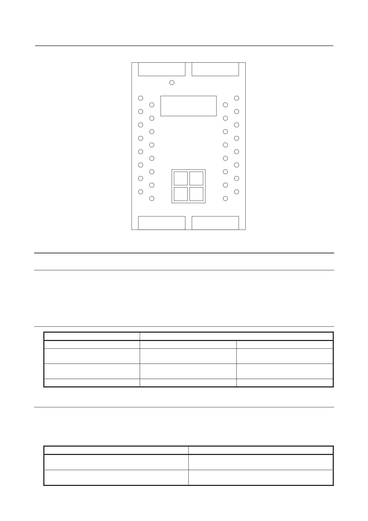
Check terminal arrangement
PIL
LM
CH1
Display
LSA2
LSA1
SM
CH1D
EXTSC2
EXTSC1
VRM
CH2
PAD
CH2D
0V
0V
PBD
PA3
PA2
Operation
PA1
PSD
buttons
PB3
PB2
PB1
5V
MODE
UP
PA4
PS2
PS1
15V
DATA
PB4
SET
DOWN
0V
0V
-15V
OVR2
4.3.6
Observing Data Using the Spindle Check Board
4.3.6.1 Overview
By using the check board, you can convert digital signals used for control in the Spindle Amplifier to analog
voltage, and observe the conversion result with an oscilloscope. For internal data observation, you can use
CH1 and CH2 (output: -5 to +5 V) as the two-channel analog output, and CH1D and CH2D as the output for
checking specific bits of bit data or the like. You can also view internal data on the five-digit indicator.
4.3.6.2 Major characteristics
Item
Measurement point
CH1, CH2
CH1D, CH2D
H: 2 Vmin
Output voltage range
-5 to +5 V
L: 0.8 Vmax
About 39 mV
Resolution
-
(10 V/256)
Output impedance
10 kΩmin
10 kΩmin
4.3.6.3 Observation method
By setting data using four DIP switches on the check board, you can output internal data to the five-digit
display, analog voltage output circuit, channels 1 and 2 (LM and SM or CH1 and CH2).
Data on channels 1 and 2 is the one from an 8-bit D/A converter.
The correspondence between channel 1/2 and the check terminal is listed below.
Measurement point
Check terminal
CH1
Channel 1
CH1D, data bit 0
CH2
Channel 2
CH2D, data bit 0
- 35 -
4.CONFIRMATION OF THE
OPERATION
START-UP PROCEDURE
B-65285EN/04
4.3.6.4 Specifying data to be monitored
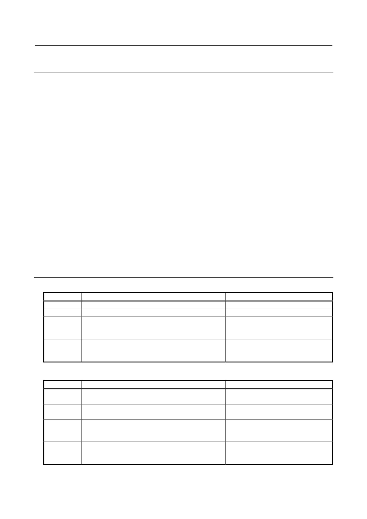
<1> Press the four setting switches at the same time for at least a second ."FFFFF" will be displayed on the
indicator.
<2> Turn off the switches and press the "MODE" switch. "d-00" will be displayed on the indicator and the
system will enter the mode for monitoring internal data.
<3> In this mode, the motor can be operated normally.
Press the "UP" or "DOWN" switch while holding down the "MODE" switch. The indicator display
will change in the range of "d-00" to "d-12".
<4> The following shows the correspondence between the destinations of the internal data of the serial
spindle and addresses d-01 to d-12.
d-01 to d-04
:
Specifies the amount of data to be output to the indicator, data shift, and output
format (decimal or hexadecimal).
d-05 to d-08
:
Specifies the amount of data to be output to the channel 1, data shift, and whether
an offset is provided.
d-09 to d-12
:
Specifies the amount of data to be output to the channel 2, data shift, and whether
an offset is provided.
<5> Select address d-xx in the procedure for setting data described in <3>.
<6> Turn off the "MODE" switch. "d-xx" will disappear 0.5 second later, and the data will be displayed for
a second.
Change the set data using the "UP" or "DOWN" switch within the second the data is displayed.
<7> When more than a second elapses without pressing the "UP" or "DOWN" switch, data cannot be
changed.
If the "MODE" switch is turned on or off, however, setting can be started from the beginning of the
step in item <6>.
4.3.6.5 Address descriptions and initial values (Spindle Amplifier)
[Output to the indicator]
Address
Description
Initial value
d-01
Specifies a data number.
0
d-02
Shift at data output (0 to 31 bits)
0
Data shift direction
d-03
0 : Data is shifted right.
0
1 : Data is shifted left.
Display format
d-04
0 : Decimal notation
0
1 : Hexadecimal notation(0 to F)
[Output to the channel 1]
Address
Description
Initial value
218
d-05
Specifies a data number
(U-phase current)
Shift at data output
d-06
8
(0 to 31 bits)
Data shift direction
d-07
0: Data is shifted right
0
1: Data is shifted left
Offset
d-08
0: Not provided
1
1: Provided
- 36 -
4.CONFIRMATION OF THE
B-65285EN/04
START-UP PROCEDURE
OPERATION
[Output to the channel 2]
Address
Description
Initial value
19
d-09
Specifies a data number
(Motor velocity)
Shift at data output
d-10
18
(0 to 31 bits)
Data shift direction
d-11
0: Data is shifted right
0
1: Data is shifted left
Offset
d-12
0: Not provided
1
1: Provided
4.3.6.6 Principles in outputting the internal data of the serial spindle
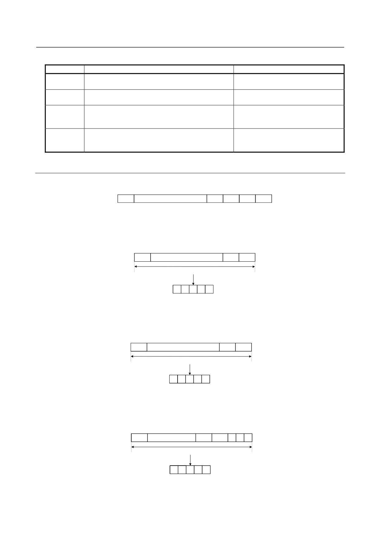
The length of data is 32 bits (BIT31 TO BIT00) unless it is described as 16 bits.
BIT31
……
BIT03
BIT02
BIT01
BIT00
(1) Example of output to the indicator
Example1: Displaying data in decimal
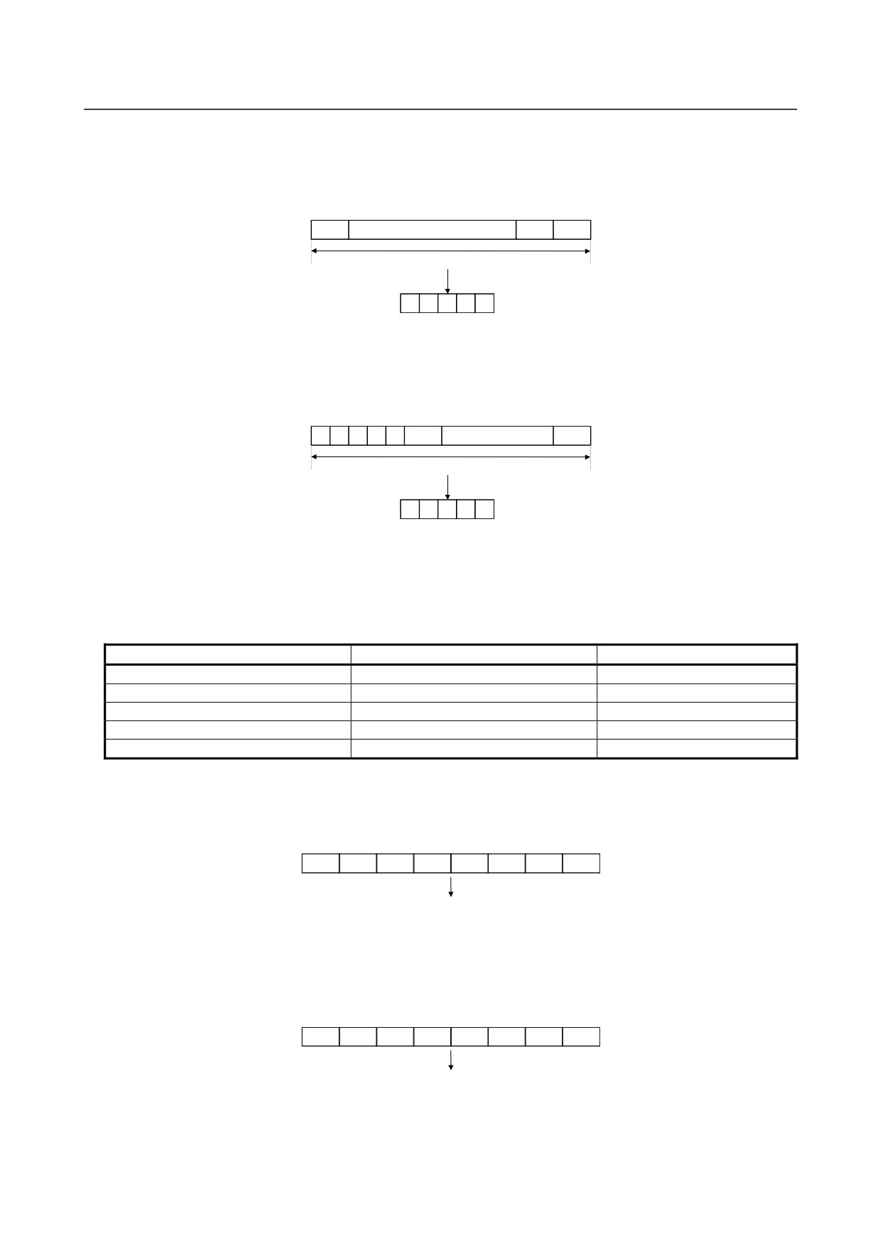
When the number of digits to shift data (d-02)=0 and display format (d-04)=0 (decimal notation): The
last 16 bits of data (BIT15 to BIT00) are converted into decimal (0 to 65535 max.) and displayed.
BIT15
……
BIT01
BIT00
16 bits
Converted into decimal
data and displayed
Indicator
X
X
X
X
X
Example2: Displaying data in hexadecimal
When the number of digits to shift data (d-02)=0 and display format (d-04)=1 (hexadecimal notation):
The last 16 bits of data (BIT15 to BIT00) are converted into hexadecimal (0 to FFFFF max.) and
displayed.
BIT15
……
BIT01
BIT00
16 bits
Converted into hexadecimal
data and displayed
Indicator
X
X
X
X
(The fifth digit is blank.)
Example3: Shifting data left
When the number of digits to shift data (d-02)=3, the shift direction is left (d-03=1), and display format
(d-04)=1 (hexadecimal notation): Data in BIT12 to BIT00 and the last three bits of data (=0) are
converted into hexadecimal (0 to FFFFF max.) and displayed.
BIT12
……
BIT01
BIT00
0
0
0
16 bits
Converted into hexadecimal
data and displayed
Indicator
X
X
X
X
(The fifth digit is blank.)
- 37 -
4.CONFIRMATION OF THE
OPERATION
START-UP PROCEDURE
B-65285EN/04
Example4: Shifting data right
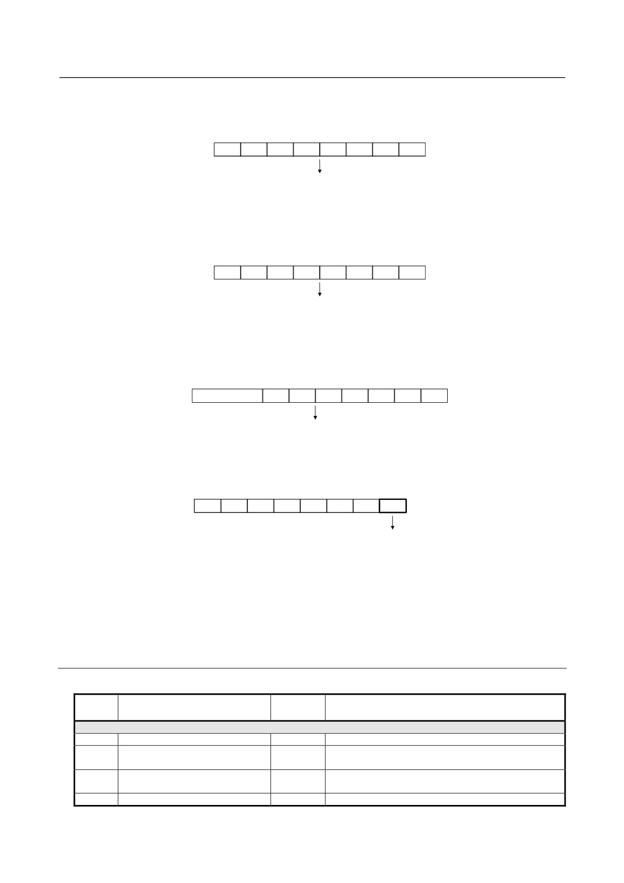
When the number of digits to shift data (d-02)=5, shift direction is right (d-03=0), and display format
(d-04)=0 (decimal notation): Data in BIT20 to BIT05 is converted into decimal (0 to 65535 max.) and
displayed.
BIT20
……
BIT06
BIT05
16 bits
Converted into decimal
data and displayed
Indicator
X
X
X
X
X
Example5: Shifting data right when the data length is 16 bits
When the data length is 16 bits, data shift (d-02)=5, shift direction is right (d-03=0), and display format
is decimal notation (d-04=0): The first five bits of data and data in BIT15 to BIT05 are converted into
decimal and displayed.
0
0
0
0
0
BIT15
……
BIT05
16 bits
Converted into decimal
data and displayed
Indicator
X
X
X
X
X
(2) Example of output to the channel 1
Internal data is output to channel 1 by setting it in an 8-bit D/A converter.
The D/A converter output ranges from -5 to +5 V, depending on a set value of internal data. See the table
below.
Internal data in binary (decimal)
Setting d-08 (whether there is offset)
Output on channel 1
00000000
(0)
0
-5V
11111111
(255)
0
+4.96V
10000000
(-128)
1
-5V
00000000
(0)
1
0V
01111111
( 127)
1
+4.96V
Example1: Data set
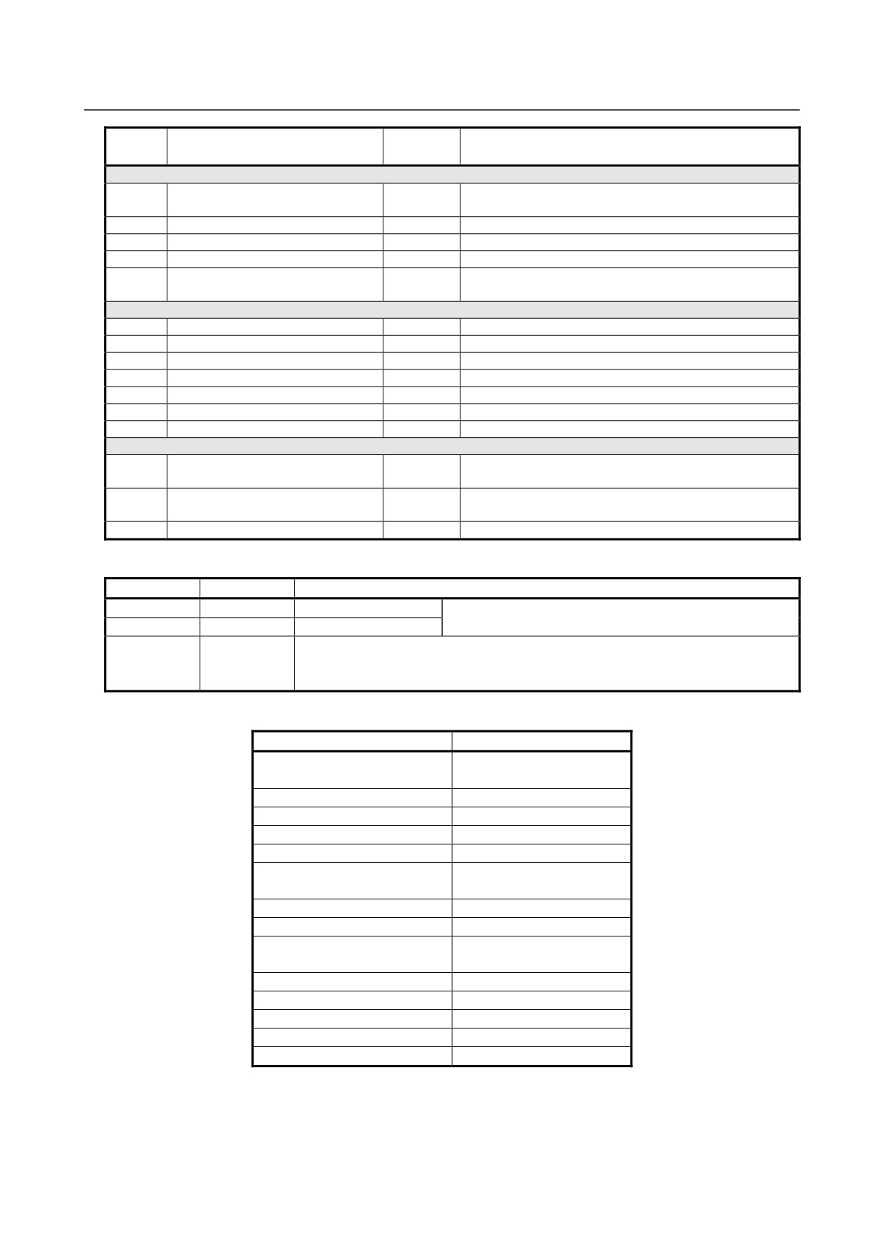
When the number of digits to shift data (d-06)=0 and when no offset is provided (d-08=0): The last
eight bits of data (BIT07 to BIT00) is set in the D/A converter of the LM terminal.
BIT07
BIT06
BIT05
BIT04
BIT03
BIT02
BIT01
BIT00
Set in the D/A converter for channel 1 output
Example2: Shifting data left
When the number of digits to shift data (d-06)=3, shift direction is right (d-07=1), and no offset is
provided (d-08=0): Data in BIT14 to BIT00 and the last three bits of data (=0) are set in the D/A
converter.
BIT04
BIT03
BIT02
BIT01
BIT00
0
0
0
Set in the D/A converter for channel 1 output
- 38 -
4.CONFIRMATION OF THE
B-65285EN/04
START-UP PROCEDURE
OPERATION
Example3: Shifting data right
When the number of digits to shift data (d-06)=10, shift direction is right (d-07=1), and no offset is
provided (d-08=0): Data in BIT17 to BIT10 is set in the D/A converter.
BIT17
BIT16
BIT15
BIT14
BIT13
BIT12
BIT11
BIT10
Set in the D/A converter for channel 1 output
Example4: Shifting data right when the data length is 16 bits
When the data length is 16 bits, data shift (d-06)=10, shift direction is right (d-07=0), and no offset is
provided (d-08=0): The first two bits of data (=0) and data in BIT15 to BIT10 are set in the D/A
converter.
0
0
BIT15
BIT14
BIT13
BIT12
BIT11
BIT10
Set in the D/A converter for channel 1 output
Example5: If an offset is provided
When the number of digits to shift data (d-06)=10, shift direction is right (d-07=0), and an offset is
provided (d-08=1): Data in most significant bit BIT17 (to which 1 is added) and data in BIT16 to
BIT10 are set in the D/A converter.
BIT17 Data +1
BIT16
BIT15
BIT14
BIT13
BIT12
BIT11
BIT10
Set in the D/A converter for channel 1 output
Example6: Data bit observation
For data shift (d-06) = 0 with no offset (d-08 = 0), the lowest data bit (BIT00) can be observed as a
high/low level at check terminal CH1D.
BIT07
BIT06
BIT05
BIT04
BIT03
BIT02
BIT01
BIT00
Output to check terminal CH1D
(3) Example of output to the channel 2
Output to the channel 2 is the same as that to the channel 1. However, the addresses for setting data (d-09 to
d-12) are different from those for output to the channel 1.
Setting velocity information in the channel 1 and the number of errors in the channel 2 enables simultaneous
monitoring of the change in each data item using the two channels.
4.3.6.7 Data numbers
(1) Data numbers
Data
Data
Description
Remarks
No.
length
Main data
16
Motor speed command
32
The 12th bit (BIT12) indicates a units in min-1.
The 12th bit (BIT12) indicates a units in min-1. (An
19
Motor speed
32
estimated value is used for the αCi series.)
(Speed command - motor speed) The 12th bit (BIT12)
25
Motor speed deviation
32
indicates a units in min-1.
4
Move command
32
Number of command pulses for ITP (usually 8 ms)
- 39 -
4.CONFIRMATION OF THE
OPERATION
START-UP PROCEDURE
B-65285EN/04
Data
Data
Description
Remarks
No.
length
Main data
Number of erroneous pulses (Spindle synchronous
9
Positioning error
32
control, Cs contour control, Rigid tapping mode)
90
Torque command
16
0 to ±16384
131
Speedometer data
16
SM terminal
132
Load meter data
16
LM terminal
Number of erroneous pulses (Position coder
136
Position error
32
orientation)
Data between the spindle and CNC
5
Speed command data
16
±16384 for the maximum speed command
6
Spindle control signal 1
16
See the command signal from the PMC to spindle in (3).
10
Load meter data
16
+32767 for maximum output
11
Motor speed data
16
±16384 for maximum speed
12
Spindle status signal 1
16
See the status signal from the spindle to PMC in (3).
66
Spindle control signal 2
16
See the command signal from the PMC to spindle in (3).
182
Spindle status signal 2
16
See the status signal from the spindle to PMC in (3).
Other data
Phase U current (A/D conversion
218
16
10 V/FS by shifting 8 bits left
data)
Phase V current (A/D conversion
219
16
data)
162
DC link voltage
16
1000 V/FS by shifting 8 bits left
(2) Internal data conversion
Data No.
Signal name
Description (All are voltage values on check pins when the shift amount is 8.)
218
IU
Phase U current
The current is positive when it is input to the amplifier. (*1)
219
IV
Phase V current
DC link voltage signal
162
VDC
100V/1V (200 V system)
200V/1V (400 V system)
*1 Current conversion result for channels 218 and 219
Model
Conversion result
αiSP 2.2
16.7A/1V
αiSP 5.5
αiiSP 11
33.3A/1V
αiSP 15
50.0A/1V
αiSP 22
66.7A/1V
αiSP 26
100A/1V
αiSP 30
133A/1V
αiSP 37
αiSP 45
150A/1V
αiSP 55
233A/1V
αiSP 5.5HV
16.7A/1V
αiSP 11HV
αiSP 15HV
33.3A/1V
αiSP 30HV
50.0A/1V
αiSP 45HV
66.7A/1V
αiiSP 75HV
133A/1V
αiSP 100HV
150A/1V
(3)
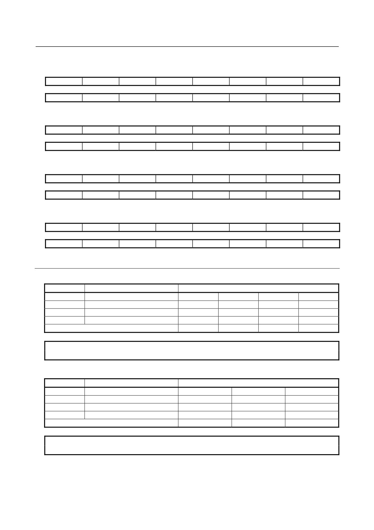
About the spindle control and spindle status signals
Shown below are the data numbers for the PMC signals used by the spindle and the configuration of
each data item. Refer to Chapter 3, "PMC Signals (CNC ↔ PMC)" of "FANUC AC SPINDLE
MOTOR αi series PARAMETER MANUAL" (B-65280EN) for explanations about each signal.
- 40 -
4.CONFIRMATION OF THE
B-65285EN/04
START-UP PROCEDURE
OPERATION
(a) Data number 6 : Spindle control signal 1
#15
#14
#13
#12
#11
#10
#9
#8
RCH
RSL
INTG
SOCN
MCFN
SPSL
*ESP
ARST
#7
#6
#5
#4
#3
#2
#1
#0
MRDY
ORCM
SFR
SRV
CTH1
CTH2
TLMH
TLML
(b) Data number 66 : Spindle control signal 2
#15
#14
#13
#12
#11
#10
#9
#8
DSCN
SORSL
MPOF
#7
#6
#5
#4
#3
#2
#1
#0
RCHHG
MFNHG
INCMD
OVR
NRRO
ROTA
INDX
(c) Data number 12 : Spindle status signal 1
#15
#14
#13
#12
#11
#10
#9
#8
RCFN
RCHP
CFIN
CHP
#7
#6
#5
#4
#3
#2
#1
#0
ORAR
TLM
LDT2
LDT1
SAR
SDT
SST
ALM
(d) Data number 182 : Spindle status signal 2
#15
#14
#13
#12
#11
#10
#9
#8
#7
#6
#5
#4
#3
#2
#1
#0
EXOF
SOREN
INCST
PC1DT
4.3.6.8 Example of observing data
(1) Example of observing a positioning error using the channel 1
Address
Description
Set Data
d-05
Data number
9
9
9
9
d-06
Data shift
0
1
1
2
d-07
Data shift direction
0
1
1
1
d-08
Offset
1
1
1
1
Data unit (NOTE)
256p/FS
512p/FS
128p/FS
64p/FS
NOTE
FS=10V (-5V to 5V)
(2) Example of observing a motor speed using the channel 2
Address
Description
Set Data
d-09
Data number
19
19
19
d-10
Data shift
12
13
11
d-11
Data shift direction
0
0
0
d-12
Offset
0
0
0
Data unit (NOTE)
256min-1/FS
512min-1/FS
128 min-1/FS
NOTE
FS=10V (-5V to 5V)
- 41 -