Hyundai SKT 100/200 CNC TURNING CENTER. INSTALLATION MAINTENANCE MANUAL (VERSION No.: VOL1.0) - page 9
APPENDIX
b)
Feedback signal level insufficient
Check the offset of the Cs contouring control one rotation signal with an oscilloscope.
⇒ Adjust the offset of the Cs contouring control one rotation signal.
c)
Detection circuit defective
⇒ Replace the printed-circuit board.
1-27. Alarm AL-41
(1)
Meaning
The position coder one rotation signal was not detected correctly.
(2)
Cause and corrective action
a)
Feedback signal cable not shielded properly
Check whether there is noise on the feedback signal. Also check whether the cable is shielded
properly.
⇒ Shield it correctly.
b)
Position coder defective Check the position coder signal.
⇒ Replace the position coder.
c) Feedback signal level insufficient (for built in sensor)
Check the feedback signal level with an oscilloscope.
⇒ Adjust so that the feedback signal level becomes the rated value.
d)
Incorrect parameter setting
Check the parameter setting and the Cs contouring control detector.
FS 0I/16/18/21
Description
4003#7,6,4
Position coder signal setting
⇒ Set the parameter correctly according to the detector used.
e)
Detection circuit defective
⇒ Replace the printed-circuit board.
A-15
1-28. Alarm AL-42
(1)
Meaning
The position coder one-rotation signal was not generated.
(2)
Cause and corrective action
a)
Feedback signal cable defective Check the connection of the cable.
⇒ Connect the cable correctly.
b)
Position coder defective Check the position coder signal.
⇒ Replace the position coder.
c)
Feedback signal level insufficient (for built in sensor)
Check the feedback signal level with an oscilloscope.
⇒ Adjust the feedback signal level.
d)
Detection circuit defective
⇒ Replace the printed-circuit board.
1-29. Alarm AL-43
(1)
Meaning
The position coder signal used for the main spindle during the
differential speed mode
was
disconnected.
(2)
Cause and corrective action
a)
Feedback signal cable defective
Check the connection of the cable. Also check for a broken wire.
⇒ Connect the cable correctly. If any wire in the cable is broken, replace the
cable.
b)
Feedback signal cable not shielded properly Check whether the cable is shielded
properly.
⇒ Shield it correctly.
c)
Position coder defective
Check the position coder signal.
⇒ Replace the position coder.
d)
Incorrect parameter setting
Check the parameter setting for the differential speed mode functions.
A-16
APPENDIX
FS 0I/16/18/21
Description
4003#5
Setting to specify use of the differential speed mode functions
⇒ Set the parameter correctly according to the function used.
e)
Detection circuit defective
⇒ Replace the printed-circuit board.
1-30. Alarm AL-44
(1)
Meaning
An A/D converter error occurred.
(2)
Cause and corrective action
a)
A/D converter defective.
⇒ Replace the printed-circuit board.
1-31. Alarm AL-46
(1)
Meaning
The position coder one rotation signal was not detected correctly during thread cutting.
(2)
Cause and corrective action
a)
Feedback signal cable not shielded properly
Check whether there is noise on the feedback signal. Also check whether the cable is shielded
properly.
⇒ Shield it correctly.
b)
Position coder defective. Check the position coder signal.
⇒ Replace the position coder.
c)
Feedback signal level insufficient (for built in sensor)
Check the feedback signal level with an oscilloscope.
⇒ Adjust so that the feedback signal level becomes the rated value.
A-17
d)
Incorrect parameter setting
Check the parameter setting and the Cs contouring control detector.
FS 0I/16/18/21
Description
4003#7,6,4
Position coder signal setting.
⇒ Set the parameter correctly according to the function used.
e)
Detection circuit defective
⇒ Replace the printed-circuit board.
1-32. Alarm AL-47
(1)
Meaning
A pulse count for the position coder signal is abnormal.
(2)
Cause and corrective action
a)
Feedback signal cable not shielded properly
Check whether there is noise on the feedback signal. Also check whether the cable is shielded
properly.
⇒ Shield it correctly.
b)
Position coder defective Check the position coder signal.
⇒ Replace the position coder.
c)
Feedback signal level insufficient (for built in sensor) Check the feedback signal level
with an oscilloscope.
⇒ Adjust so that the feedback signal level becomes the rated value.
d)
Incorrect parameter setting
Check the parameter setting and the detector.
FS 0I/16/18/21
Description
4003#7,6,4
Position coder signal setting.
⇒ Set the parameter correctly according to the detector used.
A-18
APPENDIX
e)
Detection circuit defective
⇒ Replace the printed-circuit board.
1-33. Alarm AL-49
(1)
Meaning
During differential speed mode, the sub-spindle motor speed converted from the main
spindle motor speed exceeded the limit.
(2)
Cause and corrective action
a)
The differential speed is calculated by multiplying the main spindle motor speed by the gear
ratio.
Make sure that the calculation result does not exceed the maximum motor speed.
⇒ Do not exceed the maximum motor speed.
1-34. Alarm AL-50
(1)
Meaning
During the synchronization control of the spindle, the calculation result for the speed
command exceeded the limit.
(2)
Cause and corrective action
a)
The motor speed command is calculated by multiplying the spindle speed command by the gear
ratio.
Make sure that the calculation result does not exceed the maximum motor speed.
⇒ Do not exceed the maximum motor speed.
1-35. Alarm AL-53
(1)
Meaning
The ITP signal (sync signal for sync with the CN(C) stopped.
(2)
Cause and corrective action
a)
CNC error
⇒ Check the operation of the CNC.
A-19
b)
Serial communication LSI chip defective
⇒ Replace the printed-circuit board.
1-36. Alarm AL-54
(1)
Meaning
It was detected that a high current flowed in the motor for a long period.
(2)
Cause and corrective action
a)
Overloaded operation, or frequent acceleration/deceleration
Check the load meter to see if the load is too heavy. Also check that
acceleration/deceleration was repeated frequently.
⇒ Examine the cutting conditions again.
1-37. Alarm AL-55
(1)
Meaning
During spindle switching control or speed range switching control, there was a conflict
between the switch request signal
(SPSL or RSL) and the power line state
confirmation signal (MCFN, MFNHG, or RCH, RCHH(G).
(2)
Cause and corrective action
a)
Switching umt(magnetic contactor for power line switchin(g) defective Check the
operation of the switching unit.
⇒ Replace the switching unit (magnetic contactor for power line switchin(g).
b)
Loose contact of the magnetic contactor state signal (auxiliary contact signal)
Make sure that the magnetic contactor state signal is switched properly.
⇒ Connect the magnetic contactor correctly.
c)
Incorrect parameter setting
Make sure that the parameters for the power line state signals related to spindle
switch control and output switch control are set correctly.
A-20

APPENDIX
FS 0I/16/18/21
Description
4003#5
Setting to specify use of the differential speed mode function.
4003#3
Parameter to specify the power line state signal for speed
range switching control.
⇒ Set the parameter correctly according to the system used.
1-38. Alarm AL-56
Set the parameter correctly according to the system used.
(1)
Meaning
The cooling fan for the control circuit stopped.
(2)
Cause and corrective action
a)
Cooling fan defective
Check whether the cooling fan rotates smoothly.
⇒ Replace the cooling fan.
A-21
APPENDIX
2.
Tool Post Home Position Setting
2-1. Period of Home Position Setting
Because the absolute position detector is used as the position detection system of tool post
servo, the home position setting of Tool Post should be performed in the following cases.
1 If have disassembled or reassembled the servo motor.
2 If exchanging the servo amp.
3 If exchanging the battery.
4 If disconnecting the detector connector of servo motor.
2-2. Home Position Setting Method
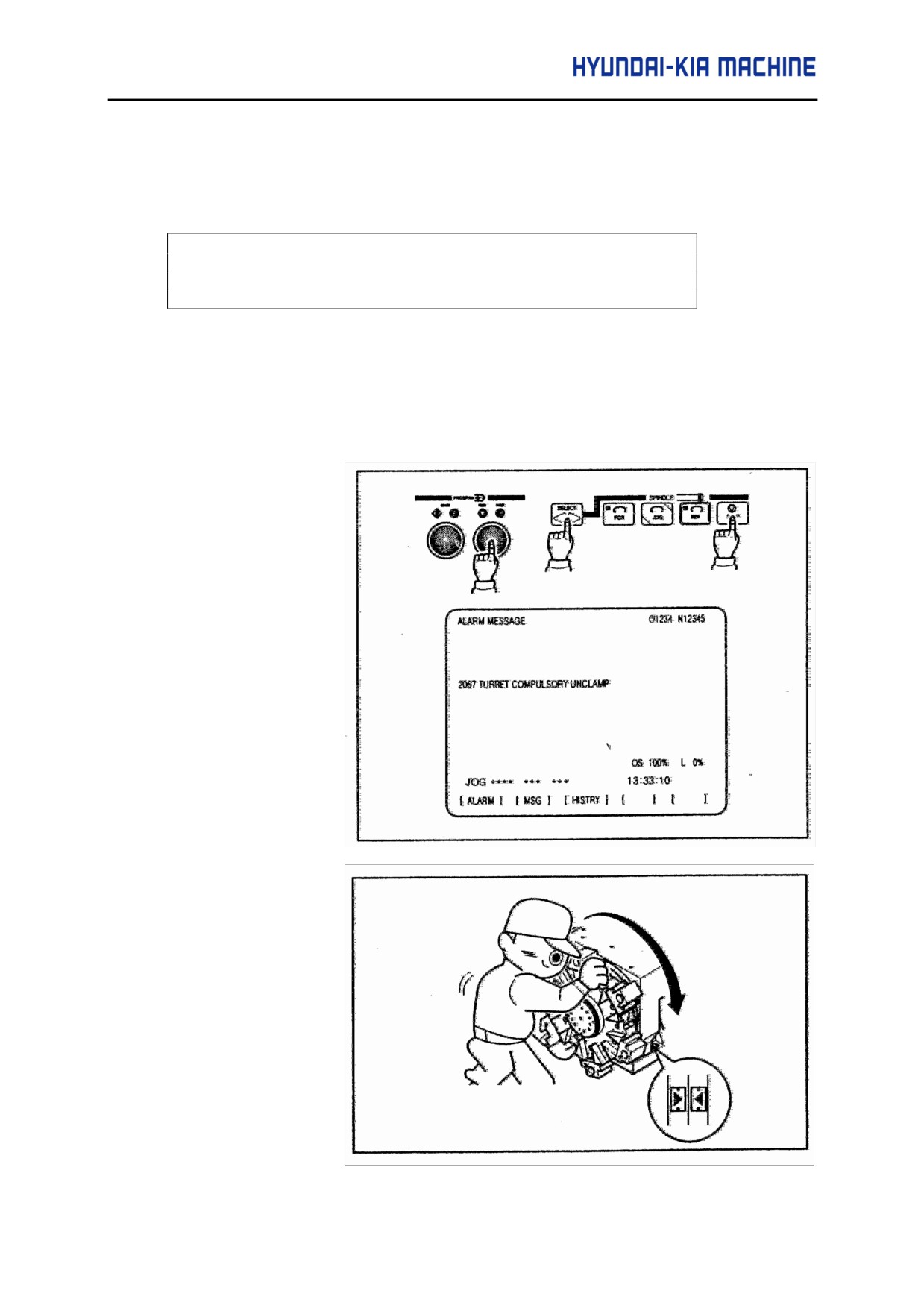
Check the Turret Clamp L/S status.(TURRET CLAMP L/S = "l") And press the "MDI" mode in
the sheet key.
(1)
Set the KEEP
RELAY
PARAMETER K5#0
=1
(2)
Unclamp the turret by
simultaneously
pressing[ Spindle
STOP]
, [SELECT],
[FEEDHOLD] on
the operating panel.
The message " 2067
TURRET COMPANY
UNCLAMP" will be
display on the alarm
screen.
(3)
Turn the turret by
hand and set the
No.1 tool.
Turn the turret and
remain it on the
position where the
arrows of turret and
tool post body are
aligned.
A-23
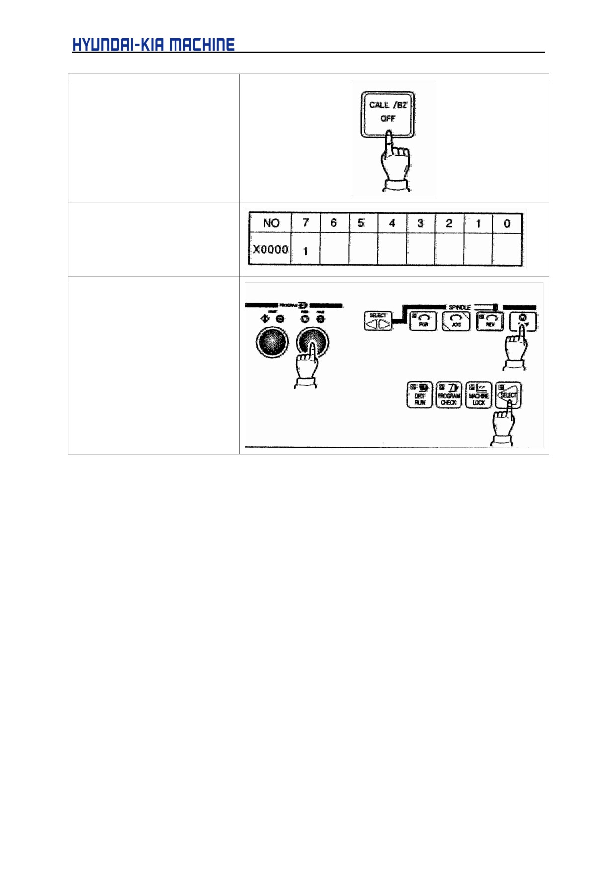
(4) Press the [CALL/BZ OFF]
switch. The turret is
clamped and "2067"
disappears on the alarm
screen.
(5) Verify that X0000.7 has
been changed to "l" in the
diagnostic screen.
(6) Set the KEEP RELAY
PARAMETER K5#0="0"
(7) Press the Spindle
[STOP]. Mode select
[SELECT] and
[FEEDHOLD] switch
simultaneously. Now the
home position setting of
the tool post is completed
and turret index is
enabled.
2-3.
TOOL NO. SETTING
Select the PMM (Power Mate CNC Manager) parameter screen.
(1)
Set the basic parameter for turret.
(Set PMM Parameter No.11#0 = "0")
(2)
Press the "MDI" mode.
(3)
Set the KEEP RELAY PARAMETER K5#0=1"
=> The Alarm Message "AL-75 TURRET ADJUST MODE" is displayed.
=> Unclamp the Turret compulsorily.
(4)
Turn the Turret by hand and set the No.1 tool.
(5)
Clamp the Turret compulsorily.
=> Set the KEEP RELAY PARAMETER K5#0="0"
(6)
Set the PMM Parameter No.11#0=”1”.
=> The Alarm Message "AL-133 POWER UNIT OFF REQUIRE" is displayed.
(7)
Turn off and then re-apply the power.
=> The Alarm Message "AL-61 TURRET SET UP ERROR" is displayed.
(8)
Press the Spindle
[STOP], mode select
[SELECT] and
[FEEDHOLD] switch
simultaneously.
A-24
APPENDIX
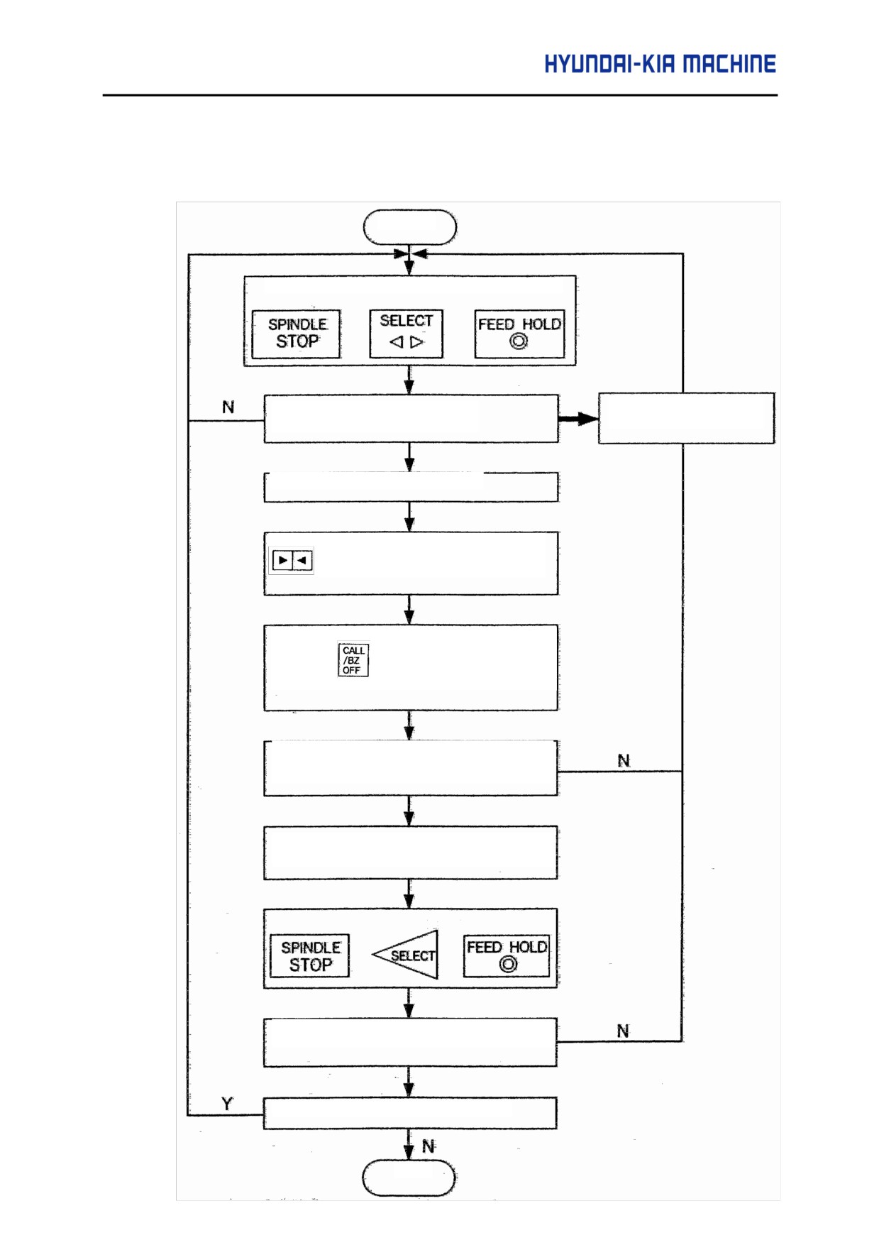
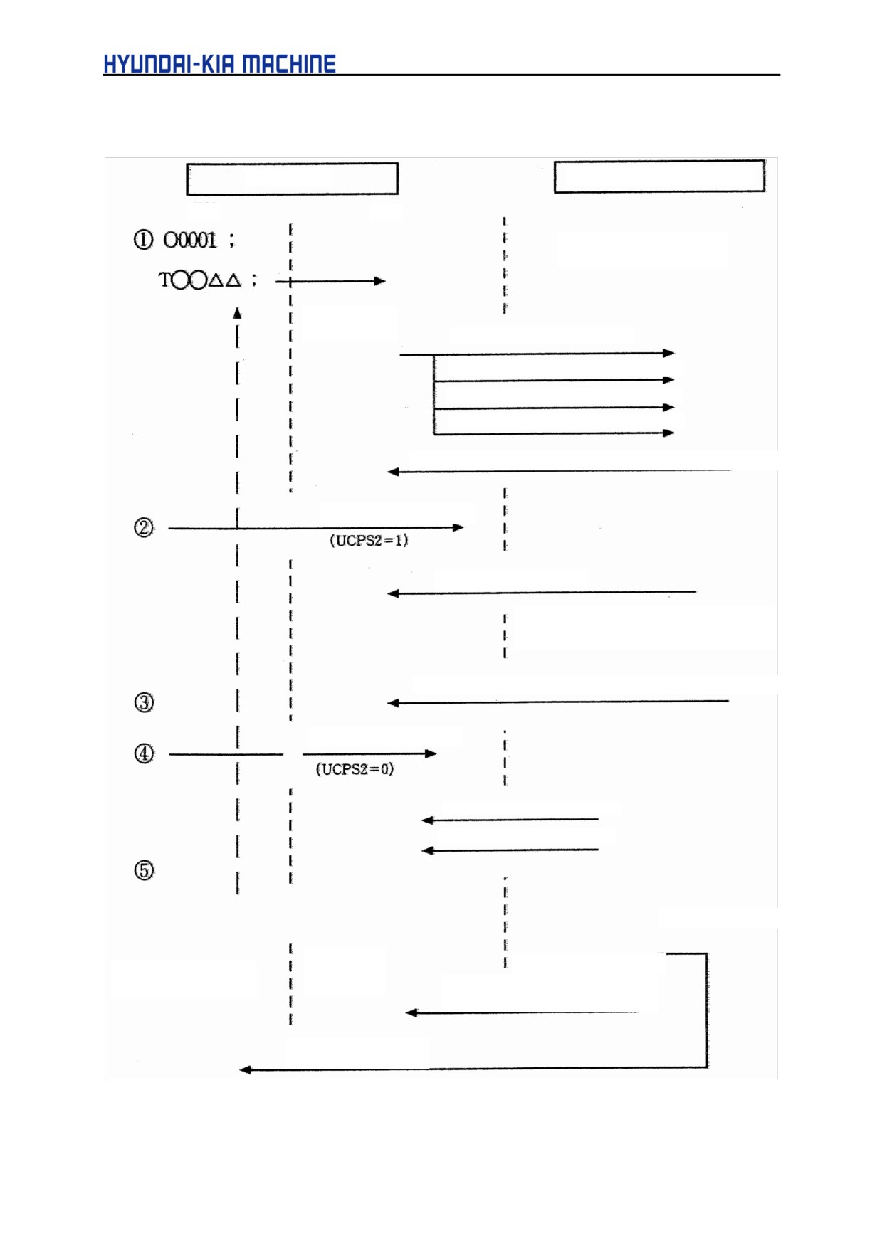
f Tool Post Home Position Setting ◄
(1) Select the MDI Mode.
(2) Set the KEEP RELAY Parameter K5#0 = "1".
(3) Adjust in the following method.
START
TURRET COMPULSORY UNCLAMP
AL-67 TURRET
The Alarm Message is displayed?
COMPULSORY UNCLAMP
(X0000.6 = "1", Y0003.7 = "1")
Turn the turret by hand
Remain it on the position where the MARKING
TURRET COMPULSORY CLAMP
Press the
s/w.
Check the Turret Clamp L/S
(X0000.7 = "1", Y0003.6 ="1")
KEEP RELAY
K5 # =0= "0", SETTING
Check the Home Position signal
(X64 # 4, #7 = ON/OFF)
Check the Turret JOG INDEX
STOP
2-4.
TURRET SERVO AMP
2-4-1.
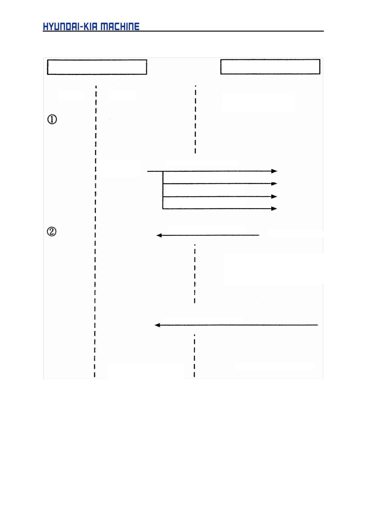
βSERVO TURRET CONTROL TIME CHART
HOST CNC
SERVO AMP UNIT
CNC
PMC
JOG & AUTO MODE
(Start enabled state)
Processing by
PMC
Function code = "2"
Command data 1 (feed type code)
Command data 2 (Turret No.)
"ST" signal or "+X, -X" signal
Operation completion 1: Unclamp command signal (UCP2)
Unclamp completion
Operation completion 2
Move command exectution, automatic
operation start state.
Operation completion 3: Clamp command signal (UCPC2)
Clamp completion
Response data (Turret N°)
Operation completion 4
Start enabled state
Processing
Alarm state occurrence
When execution is
by PMC
terminated abnomally
AL signal and the number of
alarm/alarms numbers
ALARM indication
A-26
APPENDIX
(1)
When the host NC program executes a T code command, the PMC on the host NC sets
the function code, command data 1, and command data 2, then sends the ST signal or
+X/-X signal to the servo unit. Upon receipt of the data, the servo unit returns the
operation completion 1 signal to the NC, and also outputs the unclamp command signal.
(2)
When unclamp completion notification is sent from the host NC, the servo unit returns
the operation completion 2 signal to the host NC, then starts movement to the position
corresponding to a specified turret/magazine number.
(3)
Upon completion of the movement, the servo unit returns the operation completion 3
signal to the NC, and also outputs the clamp command signal.
(4)
When clamp completion notification is sent from the host NC, the servo unit returns
response data (turret/magazine number or coordinatesland the operation completion 4
signal, and is placed in the start enabled state.
(5)
Upon receipt of the operation completion 4 signal, the PMC on the host NC returns the
FIN signal.
(6)
If an alarm is issued while the servo unit is executing an instruction, the AL signal is
output. So, the PMC on the host NC is to perform processing such as alarm indication.
In this case, the number of alarms and alarm numbers can be included in the response
data by setting the DSAL signal to 1.
[Supplementary information]
1.
The unclamp/clamp command signal and state signal are used for communication with
the host.
2.
Whether the unclamp/clamp state signal is to be checked is specified by setting bit 2
(IGCP)of parameter No. 003. When IGCP is set such that no check is to be made, the
operation completion 2 signal and operation completion 3 signal are not output.
3.
Use parameter No. 167 to set the period between the servo unit being turned on and
the output of the unclamp command signal. Use parameter No. 168 to set the period
between the clamp command signal being output and the servo unit being turned off.
4.
The "ST" signal can be accepted in the start enabled state only.
5.
The start enabled state is that state in which the STL signal is off.
A-27
2-4-2. Coordinate System Setting
HOST CNC
SERVO AMP UNIT
CNC
PMC
AUTO MODE
Start enabled state
Processinfg by
Function code = "10"
PMC
Command data 1 (Turret N° , setting)
Command data 2 (Turret N°)
"ST" signal
Operation completion 1
End of ST signal acceptance
A workpiece coordinate system is
established which uses the current
position as specified absolute
coordinates.
Operation completion 4
End of coordinate system
Start enabled state
setting
(1) In coordinate system setting, the PMC on the host NC sets the function code, command
data 1, and command data 2, then sends the ST signal to the servo unit, Upon receipt of
the data, the servo unit returns the operation completion 1 signal to the NC.
(2) Upon receipt of the operation completion 4 signal, the PMC on the host NC returns the
FIN signal.
[Supplementary information]
(1)
The start enabled state is that state in which the STL signal is off.
A-28
APPENDIX
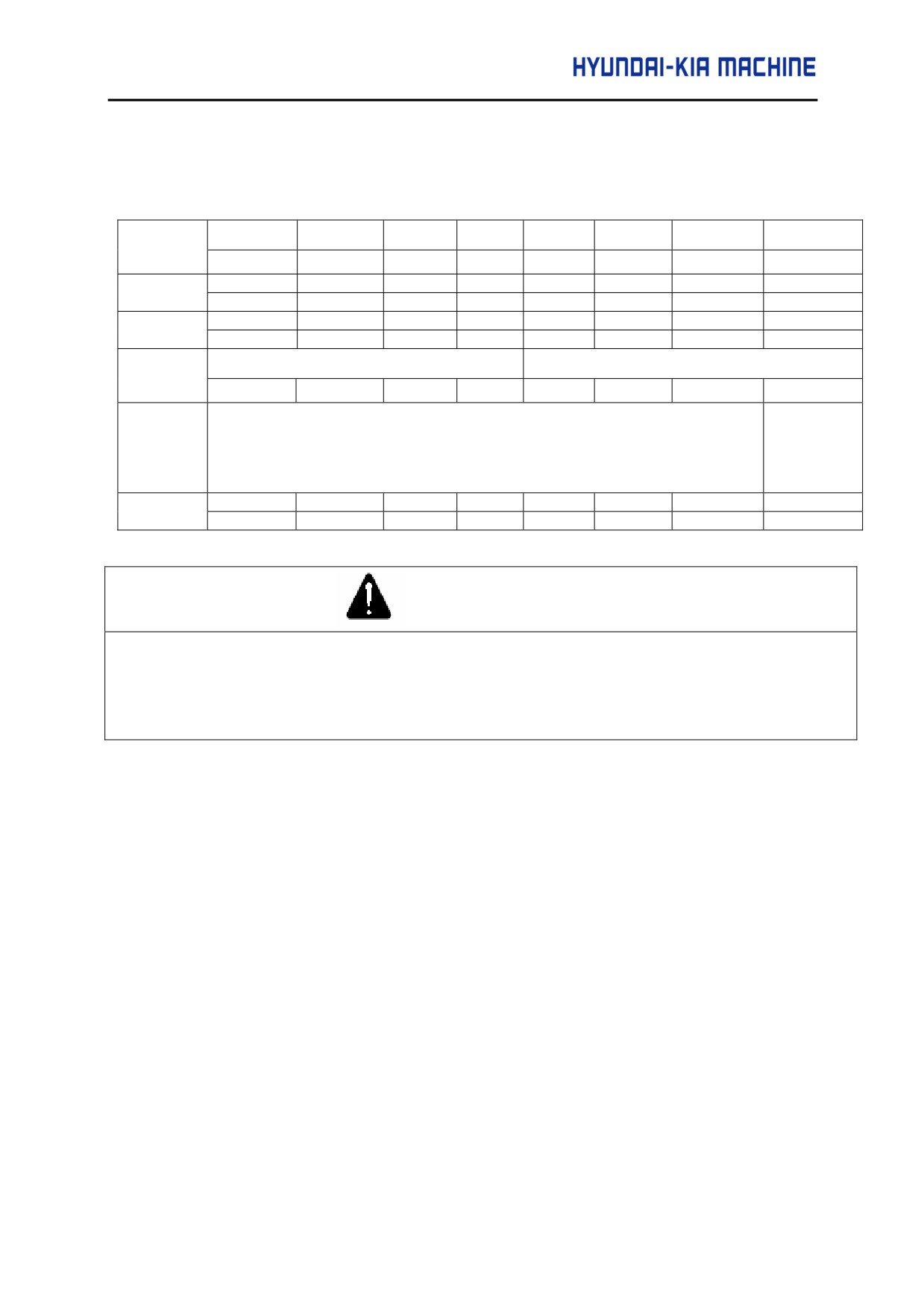
2-4-3. β DI/DO Diagnosis signal
1)
β AMP DO signal (CNC PMM)
7
6
5
4
3
2
1
0
ADDRESS
128
64
32
16
8
4
2
1
Y64
ST
UCPS2
-X
+X
DSAL
MD4
MD2
MD1
(000)
Y65
IGNVRY
DRC
ABSRD
*ILK
SVFX
*ESP
ERS
(001)
1
1
1
Y66
Function code
Command DATA 1
(002)
Y67(003)
Command DATA 2
~
(Command TOOL NO.)
Y70(006
BINARY DATA
Y71
RT
DRN
ROV2
ROV1
*OV8
*OV4
*OV2
*OV1
(007)
CAUTION
1) DGN numbers 000 to 015 correspond to signal addresses Yy+O to Yy+15, respectively.
2) DGN numbers 008 to 015 (signal addresses Yy+8 to Yy+15)are not used for the peripheral
equipment control interface.
A-29
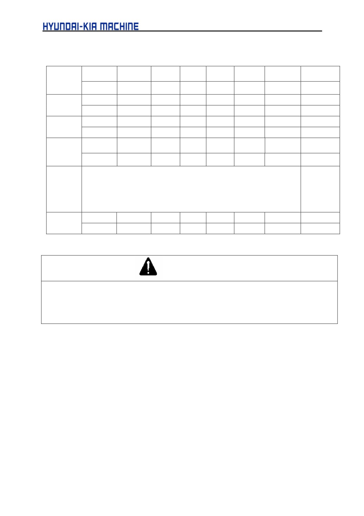
(2)
β AMP Dl signal(PMM CNC)
7
6
5
4
3
2
1
0
ADRESS
128
64
32
16
8
4
2
1
Y64
OPC4
OPC3
OPC2
OPC1
INPX
SUPX
IPLX
DEN2
(016)
1
Y65
OP
SA
STL
UCPC2
DRCO
ABSWT
(017)
1
1
MA
AL
DSP2
DSP1
DSALO
TRQM
RST
ZPX
Y66
(018)
1
1
Response DATA
Y67(019)
(Current TOOL NO.)
~
BINARY DATA
X70(022)
Y71
SVERX
PSG2
PSG1
MVX
APBAL
MVDX
(023)
1
1
CAUTION
1) DGN numbers 016 to 031 correspond to signal addresses Xx+O to Xx+15. respectively.
2) DGN numbers 024 to 031 (signal addresses Xx+8 to Xx+15)are not used for the peripheral
equipment control interface are used as response area for power motion manager.
A-30
APPENDIX
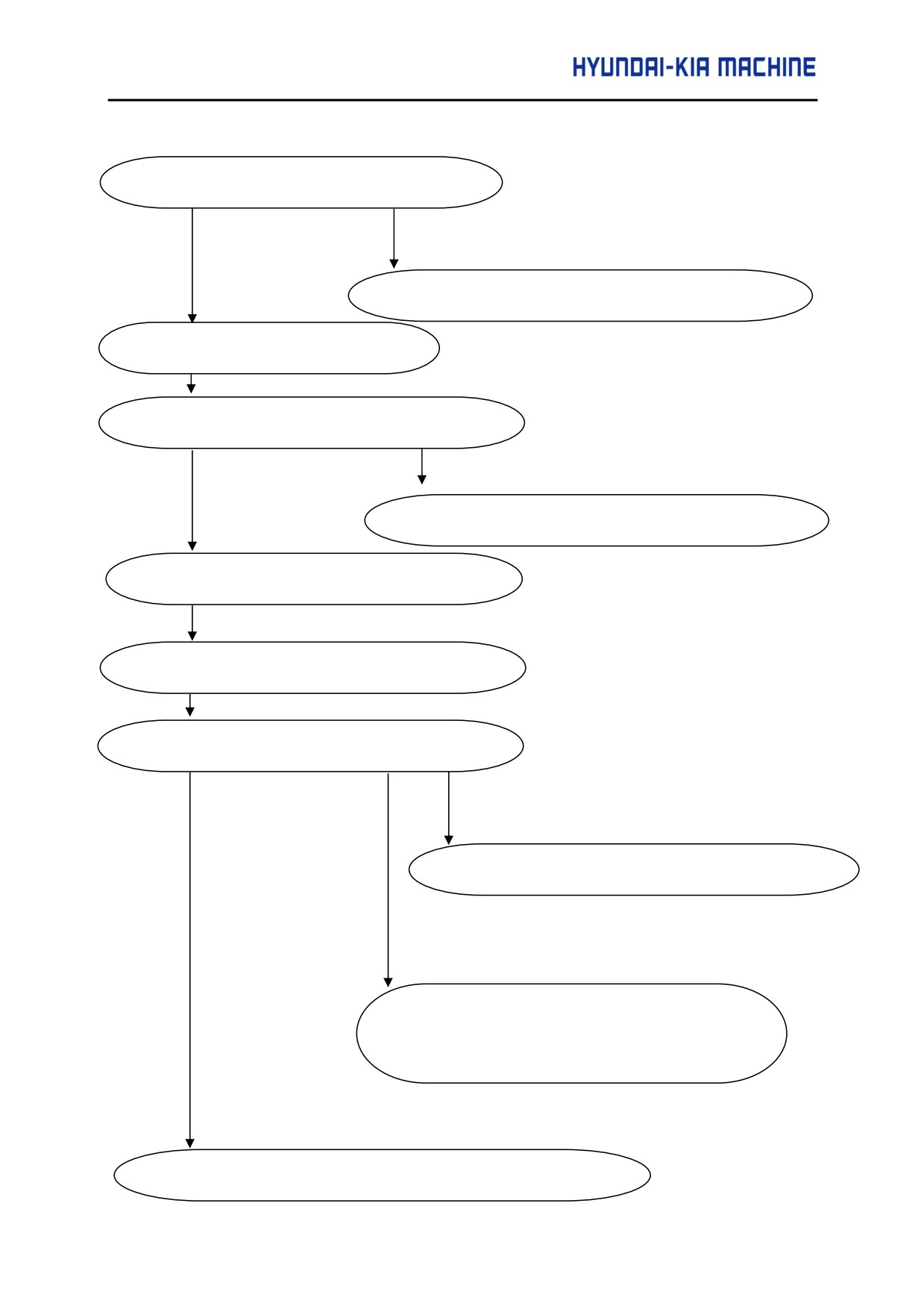
2-4-4. CHECK PROCEDURE
1. Turn on the power.
When the LED indicates data other other than - or 0
Refer to the explanation of troubleshooting in Part III .
2. The LED indicates "-" (Minus).
3. The emergency stop state is released.
The LED does not indicate "0
Check the *ESP signal applied to the servo unit.
Check the *ESP signal applied through the I/O link.
4.
The LED indicates "0" (Zero).
5.
Issue a command from the host controller.
6.
Check the operation of the servo motor.
An alarm is issued.
Refer to the explanation of troubleshooting in Part III.
The motor does not rotate.
Check the Command.
Check the parameter settings.
Check *RILK applied to the servo unit.
The motor malfunctions.
Refer to the "FANUC AC Servo Motor Parameter Manual"
A-31
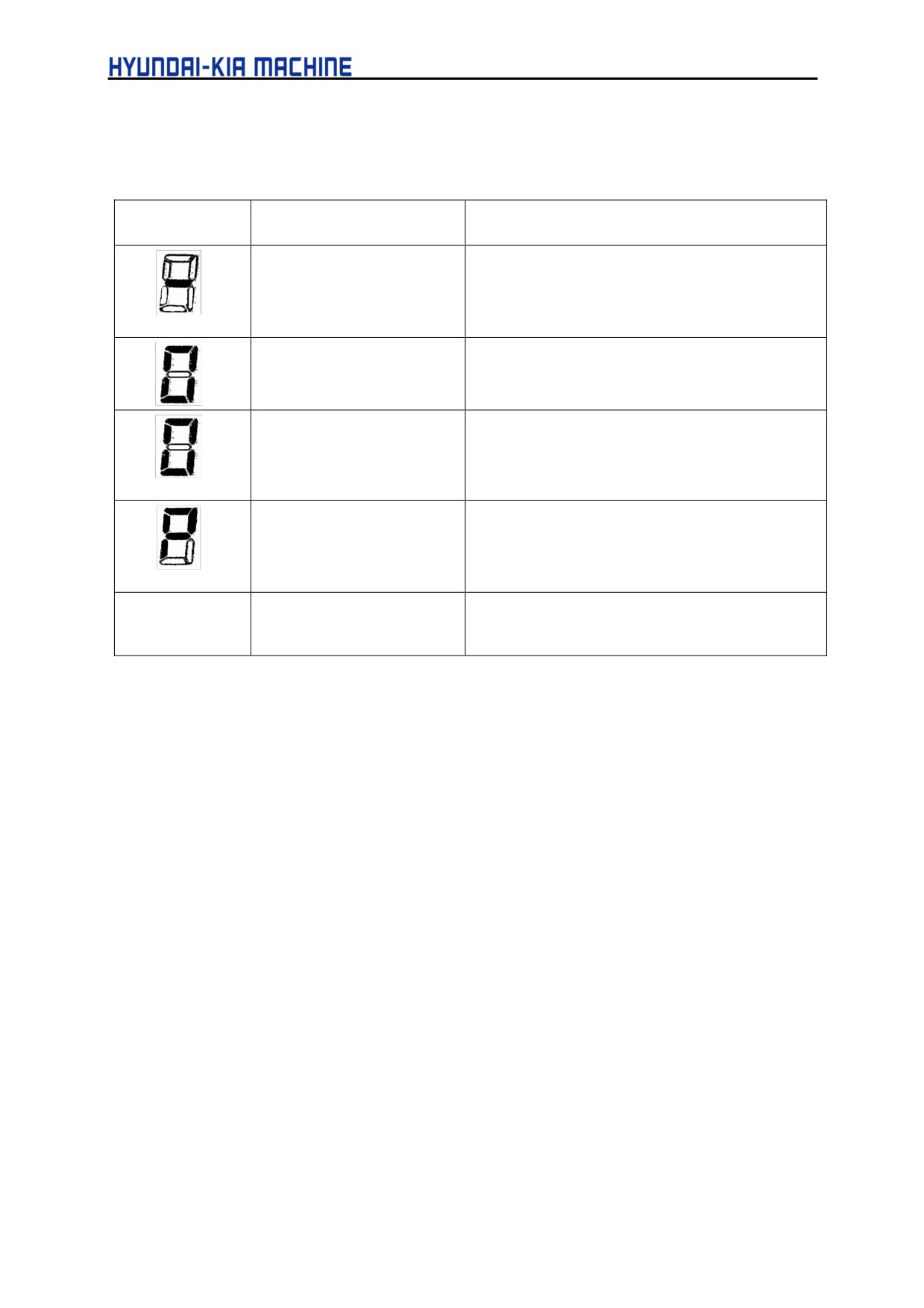
2-4-5. Check Procedure
<LED Indications and Meanings>
LED
State
Description
Amplifier not ready
This indicates that control power (+24V DC) is
supplied. No alarm is issued, but the motor is not
activated.
Amplifier ready
This indicates that the motor is activated and that
commands can now be accepted.
Command being executed
This indicates that an accepted command is now
being executed.
Blinking
Parameter being loaded.
This indicates that parameters are being loaded
in a batch from the power motion manager or
through the RS-232C interface.
Blinking
Alarm
An alarm is issued.
Indication other
For information about alarms, see the explanation
than the above
of troubleshooting in Part III.
A-32
APPENDIX
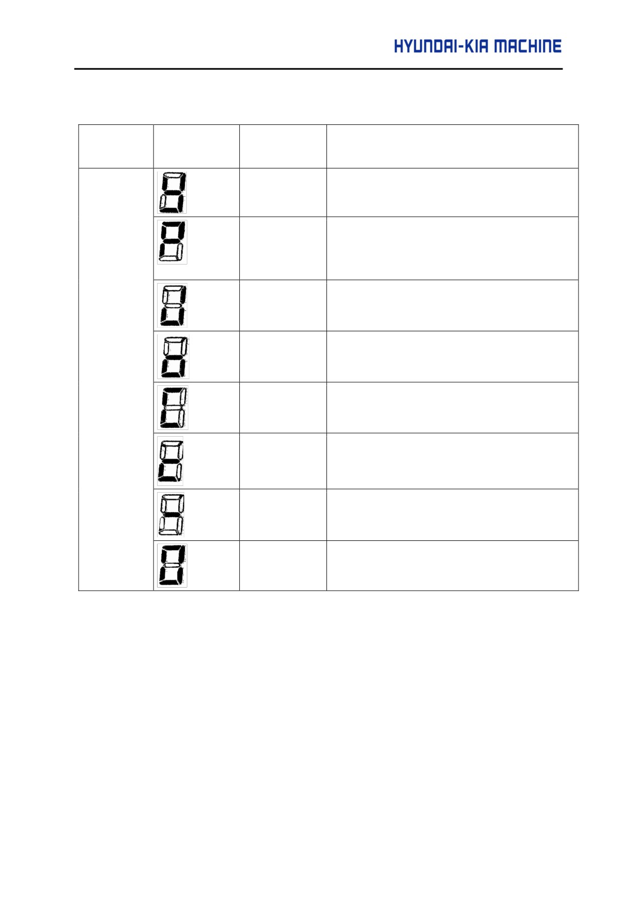
2-4-6. β SERVO AMP Alarm Detect Function
PWM board
I/O Link board
Alarm
Description
LED display
Overvoltage(HV)
This alarm is issued when the DC voltage of the
main circuit power is too high.
DC link low
This alarm is issued when the DC voltage of the
voltage
main circuit power is too low.
(LVDC)
Regenerative
This alarm is issued when the average
overheat
regenerative discharge energy is too high
(DCOH)
Overheat (OH)
The load on the motor may be too high.
Fan stop (FAL)
This alarm is issued when the fan motor built into
the servo AMP has failed.
Overcurrent
This alarm is issued when an excessively large
(HC)
current flows in the main circuit
AMP NOT
This indicates that control power (+24VDC) is
READY
supplied.
No alarm is issued, but the motor is not activated.
AMP READY
This indicates that the motor is activate, and that
commands can now be accepted.
A-33
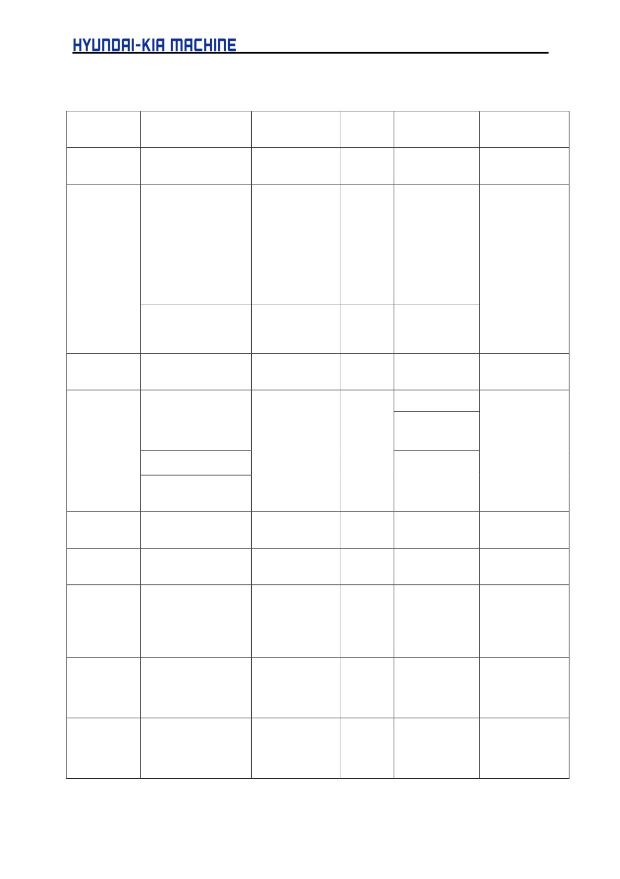
2-4-7. β AMP Function Codes
Function code
Command data 1 4
Command data 2
Mode
Start signal
Remark
Bit
4 Byte
0 :Jog
JOG
+X/-X
operation
2 :ATC
Turret/magazine
AUTO
ST
Set an amount of
operation
1: Automatic
number
travel per ATC
operation (shortcut
rotation and the
rotation)
number of
2: Automatic
turrets/magazine
operation (positive
in the
direction)
parameters.
3: Automatic
(Caution 2, 9)
operation (negative
direction)
4: 1 -pitch rotation
JOG
+X/-X
5: Continuous
indexing (Caution 1)
3 :POINT
Feedrate code 1 to 7
Point number 1
AUTO
ST
(Caution 3)
positioning
15: Rapid traverse
to 12
(Caution 4)
(Caution 5)
4 : Reference
Reference position
JOG
ST
(Caution 4)
position return
No.
(Caution 6)
1: First ZRN position
+X/-X
(Caution 8)
2: Second ZRN POS.
3: Third ZRN position
15: Reference
ST
position number
15: Reference
position external
setting
5 : Positioning
Feedrate code 1 to 7
Workpiece
AUTO
ST
(Caution 3)
(absolute
15: Rapid traverse
coordinates
specification)
6 : Positioning
Feedrate code 1 to 7
Travel distance
AUTO
ST
(Caution 3)
(Incremental
15: Rapid traverse
specification)
10 :
1: Coordinate system
Coordinates
AUTO
ST
The coordinates
Coordinate
setting
Magazine No.
corresponding to
system
2: Magazine number
Point No.
a number
setting
setting
represent the
3: Point number
current position.
setting
14 : Point
Point number 1 to 12
Point data
JOG
ST
Data is entered
data external
into the
setting
parameter
corresponding to
a point number.
15 : Data
A coordinate is
setting by
entered into
teaching
parameter
corresponding to
a point number.
A-34

APPENDIX
CAUTION
1.
If the remaining distance to the next point is shorter than the required deceleration distance for
stopping at that point when the feed axis and direction selection switch (+X, -X) is released,
movement is made to the poing immediately after the next point.
2.
Set bit 1 (ROTX) of parameter No.000 (for rotation axis setting) to 1, and set bit 7 (ROAX) of
parameter No.000 to 1 (for rollover)
3.
As the position corresponding to each point number, workpiece coordinates are set in parameter
Nos. 154 to 165.
4.
The feedrates of feedrate codes 1 to 7 are set in parameter Nos. 044 to 050. and a rapid traverse
rate is set in parameter No.040.
5.
In rollover setting, shortcut control is possible. In rollover setting, set a value within + 1 rotation for the
absolute positioning command.
6.
When a reference position is set after the power is turned on. Magazine/turret number 1 is output.
Before reference position setting, perform movement by jog operation for a minimum given distance
at a minimum given feedrate (distance and feedrate for accumulating a servo position deviation of
128 pulses or more).
7.
Normal jog feed operation can be used only when function code 0, 1, 10, or 15 is specified.
8.
When an absoulute pulse coder is used, the current position can be used as a reference position.
After positioning to a reference position, set function code 4, command data 1 = 15, jog mode, and
emergency stop release state, then turn on the ST signal.
9.
In ATC automatic operation mode, the rapid traverse rate (parameter No. 040) is used
unconditionally. In jog operation mode, the rapid traverse rate (parameter No. 040) is used when the
RT signal is turned on. The jog feedrate (parameter No. 041) is used when the RT signal is turned
off.
10.
Never change the current mode during operation 1. The mode can be changed only after operation
has been stopped.
A-35
2-4-8. SIGNAL DETAILS - The peripheral equipment
SYMB
ADD.
Description
DEN2
X64.0
Remaining travel in-range signal
This signal indicates that, in the servo unit, the number of axis move
command distribution pulses that have not been used for axis movement
(residual movement amount) is smaller than a parameter-specified value.
• The signal becomes 1 when :
- The number of axis move command distribution pulses that have not
been used for axis movement (residual movement amount) is smaller
than a parameter-specified value.
• The signal becomes 0 when :
- The number of axis move command distribution pulses that have not
been used for axis movement (residual movement amount) is larger
than a parameter-specified value.
- When the value of a parameter for the remaining travel in-range signal
is 0.
CAUTION
1. The DEN2 signal remains 0 during jog feed
(JOG).
2. The DEN2 signal maintains its current state
until another move command is issued.
IPLX
X64.1
Distribution pulse signal
This signal indicates that the servo unit has axis move command distribution
pulses that have not been used for axis movement (residual movement
amount).
• The signal is 1 when :
-
There are axis move command distribution pulses that have not been
used for axis movement (residual movement amount).
• The signal is 0 when :
-
There are no axis move command distribution pulses that have not been
used for axis movement (residual movement amount).
CAUTION
The IPLX signal is valid while jog feed (JOG)
mode is set.
SUPX
X64.2
Acceleration/deceleration pulse signal
This signal indicates that the servo unit has accumulated pulses in the
acceleration/deceleration control section.
• The signal is 1 when axis movement distribution pulses are accumulated in
the ACC/DEC control section.
• The signal is 0 when no axis movement distribution pulses are ac-
cumulated in the ACC/DEC control section.
A-36
APPENDIX
SYMB
ADD.
Description
INPX
X64.3
In-position signal
This signal indicates that the controlled axis is in position (has reached
the specified value).
• The signal is 1 when :
- There is no ACC/DEC delay (accumulated pulses) for the
controlled axis, and the servo positional deviation is within a
parameter specified range.
• The signal is 0 when :
- There is an ACC/DEC delay (accumulated pulses)for the
controlled axis.
- The servo positional deviation falls outside a parameter specified
range.
OPC1
X64.4
Operation completion signal
OPC2
X64.5
The servo unit indicates information about the completion of each function
OPC3
X64.6
code. The host executes its sequence according to this signal. See the
OPC4
X64.7
timing chart of each function code for the corresponding input timing.
•
OPC1 indicates, to the host, that the servo unit has received a command.
The servo unit issues an unclamp command signal (UCPC2 = 1) to
request the host to unclamp the machine.
• OPC2 indicates, to the host, that the servo unit has received an
unclamp completed command signal (UCPS2 = 1). The servo unit
starts axis operation.
• OPC3 is output simultaneously with the clamp command signal
(UCPC2 = 0) when axis operation is completed.
• OPC4 indicates, to the host, that the servo unit has received the clamp
completion signal (UCPS2 = 0) and finished executing all commands.
The timing at which the signal is input is set in parameter No. 166. The
clammp signal can be prevented from being used by resetting the
NCLP parameter (bit 1 of parameter No.003) to 0.
UCPC2
X65.4
Unclamp command signal
The host is responsible for clamping and unclamping the machine. The
servo unit issues this signal to request the host to clamp/unclamp the
machine when a peripheral equipment control function code command is
executed.
The signal is set to 1 when a request is issued to the host to unclamp the
machine. It is reset to 0 when a request is issued to the host to clamp the
machine. The servo unit sets the UCPC2 signal to 1 when it starts execut
ing commands whth function codes 0 and 2 to 6. When the move
command is terminated, the UCPC2 signal is reset to 0. See the timing
chart for the function codes for peripheral equipment control.
CAUTION
The UCPC2 signal is valid when the NCLP
parameter (bit 1 of parameter No. 003) is 0.
A-37
SYMB.
ADD.
Description
STL
X65.5
Automatic operation start in-progress signal The signal indicates that
automatic operation has been started.
• The signal becomes 1 when a
command to start automatic operation is issued. It becomes 0 when
automatic operation stops.
SA
X65.6
Servo preparation completion signal
This signal indicates that the servo unit is ready to operate. Conversely, if
this signal is not issured, the servo unit is not operating.
•
SA = "1"
-
Self-diagnosis in the servo system completes normally when the
power to the control unit is switched on.
-
A Servo alarm (if any has occurred) is reset.
•
SA = "0"
- The power to the control unit is switched off.
- A servo alarm condition is detected.
- An emergency stop is effected.
CAUTION
In the servo-off state, the SA signal remains
at 1 unless a condition which resets it to 0
occurs.
OP
X65.7
Automatic operation signal
This signal indicates that a series of automatic operations is in progress.
• The signal becomes 1 when a command to start automatic operation
is issued. The signal remains set to 1 even after automatic operation
stops. It becomes 0 upon the occurrence of a reset.
ZPX
X66.0
Reference position return completion signal
The signal becomes 1 when :
- Manual reference position return is completed, and the servo unit enters
the in-position state.
- Function code command-based reference position return is completed,
and the servo unit enters the in-position state.
The signal becomes 0 when the servo unit moves out of the reference
position.
RST
X66.1
Reset in-progress signal
This signal indicates that the control unit is being reset.
• The signal becomes 0 when a reset is completed.
• The signal becomes 1 when a reset is in progress.
That is, the external reset signal ERS is "1", or the emergency stop signal
*ESP is 0.
A-38
APPENDIX
SYMB.
ADD.
Description
DSALo
X66.3
Alarm output state check signal
The servo unit indicates the contents of the response data.
When the signal is 0, 1 turret, magazine, point number, or coordinates are
being output as response data. When the signal is 1, the number of alarms
and the first alarm number are being output as response data.
DSP1
X66.4
Response data check signals
DSP2
X66.5
The servo unit indicates the contents of the response data.
The servo unit specifies the response data using a combination of signals,
as listed blow.
DSP2
DSP1
Response data
1
1
Coordinate
Current position
1
0
number
AL
X66.6
Alarm signal
This signal indicates that the servo unit is in an alarm state.
• The signal becomes 1 when :
- The servo unit enters an alarm state
) P/S Alarm, Pulse Coder Alarm, Servo Alarm, Over Travel Alarm.
• The signal becomes 0 when :
- The Servo unit is released from an alarm state by a reset.
Some alarms occur again after they are reset, unless their cause is
removed. So, the AL signal is issued again immediately. In this case,
the AL signal may become 0 for a moment.
MA
X66.7
Preparation completion signal
This signal indicates that the servo unit is ready to operate.
• The signal becomes 1 when :
- Self-diagnosis in the servo unit completes normally when the power is
switched on.
- The signal becomes 0 when :
- The power to the servo unit is switched off.
- A control unit error such as a CPU or memory failure is detected.
A-39
SYMB
ADD
Description
RESPONSE
X67 ~ X70
Response data
DATA
A) The servo unit outputs the current position number (point, turret, or
magazine number) for point or ATC control. This response data is set
up upon the completion of positioning. The servo unit continues to
output the previous number until the new response data is set up.
B) Machine coordinates or workpiece coordinates can be output in real
time according to the setting of parameter No.020.
C) When the DSAL signal is 1, the servo unit outputs the number of
alarms and the first alarm number.
MVDX
X71.0
Movement direction signal
The servo unit indicates the movement direction of its controlled axis.
• The signal becomes 1 when controlled axis movement in the
negative direction begins.
• The signal is 0 when controlled axis movement in the positive
direction begins.
CAUTION
1. The MVDX signal is valid while jog feed (JOG)mode is set.
2. The MVDX signal maintains its current state during a stop. It
does not become 0 even upon a stop after movement in the
negative direction.
3. The servo unit outputs the MVX signal even during follow-up,
provided the necessary condition is satisfied.
APBAL
X71.1
Absolute pulse coder battery alarm signal
This signal indicates that the batteries of the absolute pulse coder
require replacement.
• The signal becomes 1 when :
The absolute pulse coder battery voltage is low.
• The signal becomes 0 when :
The batteries are replaced, and the battery voltage becomes
higher than or equal to the rating.
This alarm will occur again after it is reset, unless the batteries
are replaced. So, the APBAL signal is immediately issued
again. In this case, the APBAL signal may become 0 for a
moment.
A-40
APPENDIX
SYMB
ADD
Description
MVX
X71.2
Axis movement in-progress signal
The signal indicates that movement along the controlled axis is being
performed.
• The signal becomes 1 when :
- Controlled axis movement begins.
•
The signal becomes 0 when :
- Controlled axis movement ends, and the controlled axis enters
the in-positon state.
CAUTION
1. The MVX signal is valid while jog feed(JOG) mode is set.
2. The MVX signal is output even during follow-up, provided the
necessary conditions are satisfied.
PSG1
X71.3
Area signals
PSG2
X71.4
The Servo unit indicates that the current machine coordinates are
within a parameter-specified range, using two code signal outputs.
CAUTION
The servo unit outputs the PSG1 and PSG2 signals even
during follow-up, provided the necessary condition is satisfied.
SVERX
X71.6
Servo positional deviation monitor signal
This signal indicates that, in the servo unit, the amount of servo
positional deviation has exceeded a parameter-specified value.
• The signal is 1 when the servo positional deviation amount is
larger than a parameter-specified value.
• The signal is 0 when:
- A parameter-specified value for the servo positional deviation
amount is 0
- The servo positional deviation amount is within a parameter-
specified range.
A-41
SYMB
ADD
Description
MD1
Y64.0
Mode selection signal
MD2
Y64.1
This signal selects an operation mode.
MD4
Y64.2
The signal is a code signal consisting of three bits: MD1, MD2, and
MD4. The code signal selects one of three modes: automatic operation
(AUTO), handle feed(HANDLE), or jog(JOG), according to the
combinatin of these bits.
MD1
MD2
MD4
Description
1
0
0
Automatic operation (AUTO)
0
0
1
Handle feed (HANDLE)
1
0
1
Jog feed by +X and -X(JOG)
CAUTION
Do not switch the operation mode during automatic operation.
Stop automatic operation before switching the operation mode.
DSAL
Y64.3
Alarm out command signal
The host specifies that alarm information be output as response data.
When DSAL is 1, the following information is output as response data.
X67
Number of alarm (byte type)
X68.X69
Alarm number (word type)
When the signal is 0, a turret, magazine, point number, or coordinates
are output as response data, when the signal is 1, the number of
alarms and the first alarm number are output as response data.
+X -X
Y64.4
Feed axis and direction selection signals These signals select the
Y64.5
direction in which jog feed movement (rotation) is to be performed, and
cause it to be performed in the selected direction.
- The signals are
valid when jog feed (JOG) is selected. They indicate the direction of
feed, from 0 to 1 causes and keeps movement in the corresponding
direction at a feedrate specified by the override signals *0V1 to *0V8 or
the manual rapid traverse selection signal RT, provided the signal is 1.
CAUTION
1. Simultaneously setting +X and -X to 1 results in neither
direction being selected (dquivalent to when both are
0).
2. If a feed axis selection signal becomes 1 before the jog
feed selection signal (JOG) becomes 1, it must be reset
to 0 before the feed axis selection signal is set. The
servo unit begins feeding when the JOG signal rises.
A-42
APPENDIX
SYMB
ADD
Description
STL
X65.5
Clamp/unclamp state output signal
When the servo unit requests clamping/unclamping of the machine,
using the UCPC2 signal, the host actually clamps/unclamps the
machine.
Upon the completion of clamp/unclamping, it reports it to the servo unit,
which then proceeds to the next processing.
The signal is set to 1 when machine is undamped.
When it is clamped, the signal is reset to 0.
See the timing chart for the
function codes for peripheral equipment control.
CAUTION
The UCPS2 signal is valid when the NCLP parameter (bit 1 of
parameter No.003) .is 0.
SA
X65.6
Automatic operation start signal The host starts function code
commands, such as part of peripheral equipment control ATC
operations and point positioning. Specifically, the host issues a direct
command to start 32-block buffering. When the ST signal is set to 1
then reset to 0 again, the servo unit begins operating.
CAUTION
It is also possible to start operation at the rising edge (form
off to ton) of the ST signal as specified by the STON
parameter (bit 7 of parameter No.003)
OP
X65.7
External reset signal
This signal resets the servo unit.
• When the signal becomes 1, the servo unit operates as follows :
- The servo unit immediately decelerates axis movement to a
stop.
- After as. stop, the servo unit is reset, then the following are
canceled :
) Function code commands being executed, buffered, and
sent as an input signal.
) Alarm condition (if any).
- While the external reset signal is 1, jog and function code
commands cannot be issued.
RST
X66.1
Emergency stop signal
This signal brings the control unit to an emergency stop.
- The control unit decelerates axis movement to a stop immediately.
- A reset is applied after the stop.
- When the emergency stop signal is 0, the servo preparation
completion signal SA is also 0, because the servo system is not
operating, the amount of movement is reflected in the current
position coordinates held in the control unit (follow-up)
- While the emergency stop signal is 0, jog and function code
commands cannot be issued.
A-43
SYMB
ADD
Description
SVFX
X65.2
Servo-off command signal
The host turns off the servo circuit for a controlled axis, that is, shuts off
the current to the servo motor of the controlled axis. This disables
positioning control. Position detection continues, however. So, the
current position will not be lost.
The servo motor remains off while the signal is 1. If the machine is
moved by the application of external force, its coordinates are shifted,
because positioning control does not work during the servo-off state.
How the shifted machine coordinates are handled can be selected by a
parameter, as follow:
1. The machine coordinate shift is recorded in an error counter.
When the servo-off signal becomes 0, the machine moves to cancel out
the error recorded in the error counter.
2. Follow-up is performed.
The machine coordinate shift is regarded as being the result of a
command, and the control unit adjusts its current position data so that
the error counter becomes 0. With this method, the machine remains in
a shifted position even after the servo-off signal becomes 0. However,
the machine moves to the correct position the next time an absolute
command is issued, because the control unit has information about the
correct position.
[USE]
Generally, method (1) above is used to prevent excessive current
flowing through the servo motor when it is clamped mechanically with a
force stronger than the servo motor can generate. Usually, the host
keeps the inter lock signal at 0 while the servo-off signal is 1. Generally,
method (2) is used to operate the machine by rotating the motor with a
handle feed mechanism.
*ILK
Y65.3
Inter lock signal
The host stops sending jog feed and function code commands.
• When the *ILK signal is 0, the host resets jog feed and function code
command signals to 0 to decelerate and stop controlled axis feed.
When it becomes 1, movement is resumed immediately. No command
other than a move command is affected.
CAUTION
The interlock signal is valid when jog feed (-X or +X) is being
performed based on the jog feed selection signal (JOG).
A-44
APPENDIX
SYMB
ADD
Description
IGNVRY
Y65.6
V READY OFF alarm ignore signal
This signal is used to disable the detection of "Servo alarm (No.0401): V
ready off" for the controlled axis.
When the signal becomes 1, the control unit behaves as follows:
• Even when the servo amplifier preparation completion signal is off, "servo
alarm (No.401) : V ready off" is not detected. The Servo preparation
completion signal SA becomes 0, however.(This signal can be held at 1
using the SAK parameter (bit 0 of parameter No.004)
COM. Data
Y66.0
Command data 1
1
~
The host sets command data 1 to specify the feed rate for peripheral
Y66.3
equipment control.
FUNC.
Y66.4
Function code
Code
~
The host sets the peripheral equipment control function code.
Y66.7
COM. Data
Y67
Command data 2
2
~
The host sets command data 2 to specify the amount of movement for
Y70
peripheral equipment control.
*OV1 ~
Y71.0
Override signals
*OV8
Y71.1
The host applies override to jog feed and cutting feedrates.
Y71.2
Y71.3
*OV8
*OV4
*OV2
OV1
"Override
*OV8
*OV4
*OV2
*OV1
*Override
1
1
1
1
0
0
1
1
1
80
1
1
1
0
10
0
1
1
0
92
1
1
0
1
20
0
1
0
1
100
1
1
0
0
30
0
1
0
0
110
1
0
1
1
40
0
0
1
1
120
1
0
0
1
60
0
0
0
1
140
1
0
0
0
70
0
0
0
0
150
Actual jog feed and automatic cutting feedrates are obtained by multiplying
the respective specified values by the override values.
A-45