Hyundai SKT 100/200 CNC TURNING CENTER. INSTALLATION MAINTENANCE MANUAL (VERSION No.: VOL1.0) - page 8
#7#
6tt
5#
4#
3#
2#
1#
#0
203
DTE
CRC
STB
PRM
#7(DTE) : The serial pulse coder encountered a communication error.
The pulse coder, feedback cable, or feedback receiver circuit is defective.
Replace the pulse coder, feedback cable, or NC-axis board.
#6(CRC) : The serial pulse coder encountered a communication error.
The pulse coder, feedback cable, or feedback receiver circuit is defective.
Replace the pulse coder, feedback cable, or NC-axis board.
#5(STB) : The serial pulse coder encountered a communication error.
The pulse coder, feedback cable, or feedback receiver circuit is defective.
Replace the pulse coder, feedback cable, or NC-axis board.
#4(PRM) : An invalid parameter was found. Alarm 417(invalid servo parameter) is also issued.
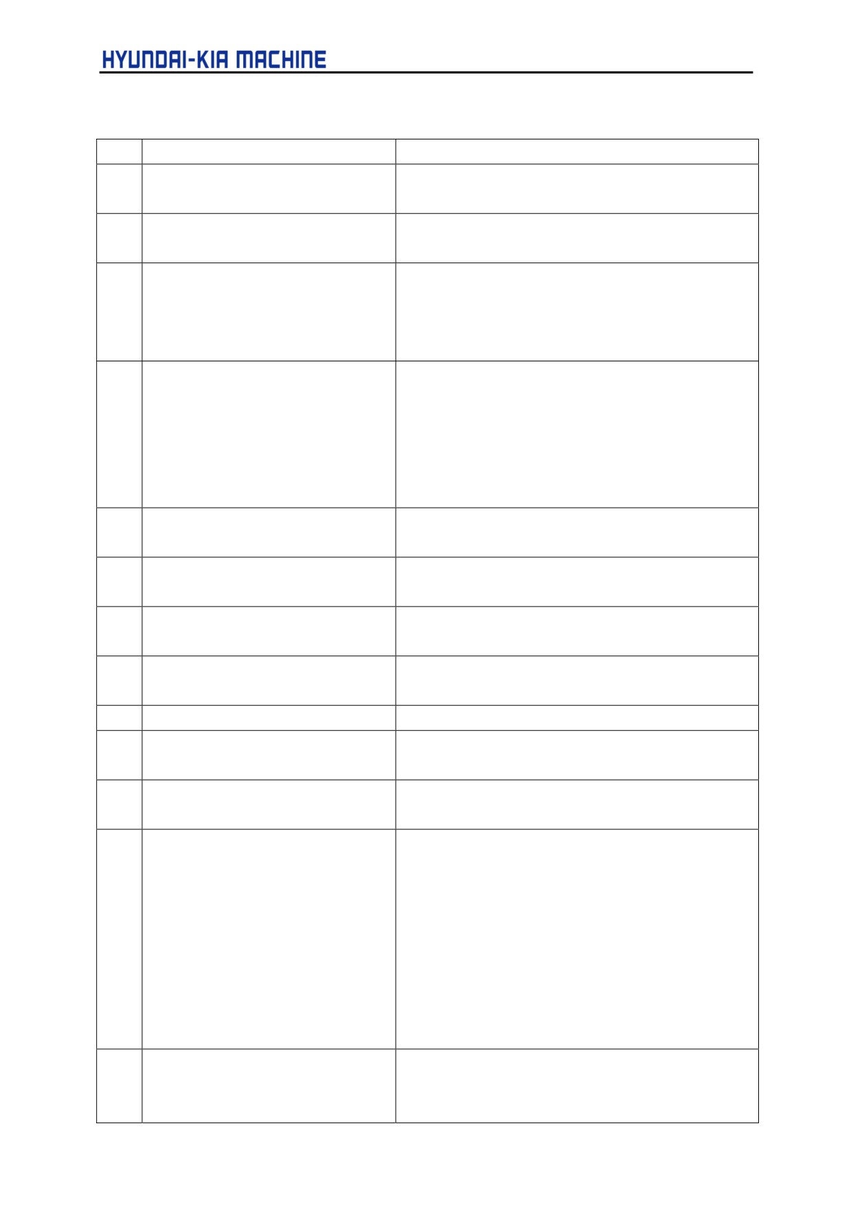
6) Servo alarms(l/2)
No.
Message
Contents
401
SERVO ALARM : n-TH AXIS VRDY
The n-th axis (axis 1-8) servo amplifier READY signal
OFF
(DRDY) went off. Refer to procedure of trouble
shooting.
402
SERVO ALARM : SV CARD NOT
The axis control card is not provided.
EXIST
403
SERVO ALARM : CARD /SOFT
The combination of the axis control card and servo
MISMATCH
software is illegal. The possible causes are as
following:
•
A correct axis control card is not provided.
•
Correct servo software is not installed on flash
memory.
404
SERVO ALARM n-TH AXIS VRDY
Even though the n-th axis (axis 1-8) READY signal
ON
(MCON) went off, the servo amplifier READY signal
(DRDY) is still on. Or, when the power was turned on.
DRDY went on even thought MCON was off. Check that
the servo interface module and servo amp are
connected.
405
SERVO ALARM: (SERVO POINT
Position control system fault. Due to an NC or servo
RETURN FAULT)
system fault in the reference position return, there is the
possibility that reference position return could not be
executed correctly.
Try again from the manual reference position return.
5-130
V. REPAIR AND PRESERVATION
No.
Message
Contents
407
SERVO ALARM: EXCESS ERROR
The following error occurred during simple
synchronous control :
The difference in machine coordinates between the
synchronized axes exceeds the value set in parameter
No.8314.
409
SERVO ALARM :n AXIS TORQUE
Abnormal servo motor load has been detected.
ALM
Alternatively, abnormal spindle motor load has been
detected in Cs mode.
410
SERVO ALARM : n-TH AXIS
One of the following errors occurred :
EXCESS ERROR
1) The positional deviation value when the n-th axis
stops exceeds the value set in parameter No. 1829.
2) In simple synchronous control, the compensation
amount for synchronization exceeds the value set in
parameter No.8325.
This alarm is issued only for the slave axis.
411
SERVO ALARM : n-TH AXIS
The position deviation value when the n-th axis (axis
EXCESS ERROR
1-8) moves is larger than the set value. Refer to
procedure of trouble shooting.
413
SERVO ALARM : n-TH AXIS LSI
The contents of the error register for the n-th axis (axis
OVERFLOW
1-8) exceeded ±231 power. This error usually occurs as
the result of an improperly set parameters.
415
SERVO ALARM : n-TH AXIS
A speed higher than 524288000 units/s was attempted
EXCESS' SHIFT
to be set in the n-th axis (axis 1-8). This error occurs as
the result of improperly set CMR.
417
SERVO ALARM : n-TH AXIS DGTL
This alarm occurs when the n-th axis (axis 1-8) is in one
PARAMETER
of the conditions listed below (Digital servo system
alarm).
1) The value set in Parameter No.2020(motor form) is
out of the specified limit.
2) A proper value (111 or -111) is not set in parameter
x 'No. 2022(motor revolution direction).
3) Illegal data(a value below
0, etc.) was set in
parameter No.2023( number of speed feedback
pulses per motor revolution).
4) Illegal data
(a value below
0, etc.) was set in
parameter No.2024(number of speed feedback
pulses per motor revolution).
5) Parameters No. 2084 and No. 2085(flexible field
bear rate) have not been set.
6) A value outside the limit of {1 to the number of
control axes} or a non-continuous value (parameter
1023(servo axis number) contains a value out of the
range form 1 to the number of axes, or an isolated
value (for example, 4 not preceded by 3) was set in
parameter No. 1023(servo axis number).
7) A torque control parameter is set incorrectly in PMC
axis control. (The torque constant parameter is set
to 0.)
5-131
No.
Message
Contents
420
SERVO ALARM:n AXIS SYNC
During simple synchronous control, the difference
TORQUE
between the torque commands for the master and
slave axes exceeded the value set in parameter
No.2031.
421
SERVO ALARMS AXIS EXCEES
The difference between the errors in the semi-closed
ER(D)
loop and closed loop has become excessive during
dual position feedback. Check the values of the dual
position conversion coefficients in parameters No.2078
and 2079.
422
SERVO ALARM:n AXIS
In torque control of PMC axis control, a specified
allowable speed has been exceeded.
423
SERVO ALARM :n AXIS
In torque control of PMC axis control, the parameter-set
allowable cumulative travel distance has been
exceeded.
430
n AXIS:SV. MOTOR OVERHEAT
A servo motor overheat occurred.
431
n AXIS:CNV.OVERLOAD
1) PSM : overheat occurred.
2) β series SNU : Overheat occurred.
432
n AXIS:CNV.LOW VOLT CONTROL
1) PSM : Control power voltage has dropped.
2) PSMR : The control power supply voltage has
dropped.
3) β series SNU : The control power supply voltage has
dropped.
433
n AXIS:CNV.LOW VOLT DC LINK
1) PSM : The DC link voltage has dropped.
2) PSMR : The DC link voltage has dropped.
3) α series SVU : The DC link voltage has dropped.
4) β series SNU : The DC link voltage has dropped.
434
n AXIS:INV.LOW VOLT CONTROL
SVM : The control power supply voltage has dropped.
435
n AXIS:INV.LOW VOLT CONTROL
SVM : The DC link voltage has dropped.
436
n AXISrSOFTTHERMAL (OVC)
The digital servo software detected the soft thermal
state (OVC).
437
n AXIS:CNV. OVERCURRENT
PSM : Overcurrent flowed into the input circuit.
438
n AXIS: IN V. ABNORMAL
1) SVM : The motor current is too high.
CURRENT
2) α series SVU : The motor current is too high.
3) β series SNU : The motor current is too high.
439
n AXIS :CNV.OVER VOLT POWER
1) PSM : The DC link voltage is too high.
2) PSMR : The DC link voltage is too high.
3) αseries SVU : The C link voltage is too high.
4) β series SNU : The link voltage is too high.
5-132
V. REPAIR AND PRESERVATION
No.
Message
Contents
440
n AXIS:CNV.EX DECELERATION
1) PSMR : The regenerative discharge amount is too
POW.
large.
2) α series SVU : The regenerative discharge amount
is tool large. Alternatively, the regenerative
discharge circuit is abnormal.
441
n AXIS:ABNORMAL CURRENT
The digital servo software detected an abnormality in
OFFSET
the motor current detection circuit.
442
n AXIS:CNV.CHARGE FAILURE
1) PSM : The spare discharge circuit of the DC link is
abnormal.
2) PSMR : The spare discharge circuit of the DC link is
abnormal.
443
n AXIS:CNV.COOLING FAN
1) PSM : The internal stirring fan failed.
FAILURE
2) PSMR : The internal stirring fan failed.
3) β series SVU : The internal stirring fan failed.
444
n AXIS:INV. COOLING FAN
SVM : The internal stirring fan failed.
FAILURE
445
n AXIS:SPOT DISCONNECT ALARM
The digital servo software detected an broken wire in
the pulse coder.
446
n AXIS:HARD DISCONNECT
A broken wire in the built-in pulse coder was detected
ALARM
by hardware.
447
n AXIS:HARD . DIS,CONNECT(EXT)
A broken wire in the separate detector was detected by
hardware.
448
n AXIS:UNMATCHED FEEDBACK
The sign of feedback data from the built-in pulse coder
ALARM
differs from that of feedback data from the separate
detector.
449
n AXIS:INV.IPM ALARM
1) SVM : IPM(intelligent power modual) detected an
alarm.
2) α series SVU
: IPM(intelligent power modual)
detected an alarm.
453
n AXIS:SPC SOFT DISCONNECT
Software disconnection alarm of the α pulse coder.
ALARM
Turn off the power to the CNC, then remove and insert
the pulse coder cable. If this alarm is issued again,
replace the pulse coder.
456
ILLEGAL CURRENT LOOP
The current control cycle setting (parameter No.2004,
bit
0 of parameter No.2003, and bit 0 of parameter
No.2013) are incorrect.
- For the two axes whose servo axis numbers (setting
of parameter No.1023) are an odd number followed
by an even number (a pair of axes 1 and 2 or axes 5
and 6, for example), a different current control cycle is
set for each of the axes.
- The requirements for slaves needed for the set
current control cycle, including the number, type, and
connection method of them, are not satisfied.
5-133
No.
Message
Contents
457
ILLEGAL HI HRV (250US)
Use of high-speed HRV is specified although the
current control cycle is 200µs.
458
CURRENT LOOP ERROR
The current control cycle setting does not match the
actual current control cycle.
459
HI HRV SETTING ERROR
Of two axes having adjacent servo axis numbers
(parameter No.1023), odd number and even number,
high-speed HRV control can be performed for one axis
and not for the other.
460
n AXIS:FSSB DISCONNECT
FSSB communication was disconnected suddenly. The
possible causes are follows :
1) The FSSB communication cable was disconnected
or broken.
2) The power to the amplifier was turned off suddenly.
3) A low-voltage alarm was issued by the amplifier.
461
n AXIS ILLEGAL AMP INTERFACE
The axes of the 2-axis amplifier were assigned to the
fast type interface.
462
n AXIS: SEND CNC DATA FAILED
Because of an FSSB communication error, a slave
could not receive correct data.
463
n AXIS: SEND SLAVE DATA FAILED
Because of an FSSB communication error, a servo
system could not receive correct data.
464
n AXIS: WRITE ID DATA FAILED
An attempt was made to write maintenance information
on the amplifier maintenance screen, but it failed.
465
n AXIS: RE AD ID DATA FAILED
At power-up, amplifier initial ID information could not be
read.
466
n AXIS: MOTOR/AMP
The maximum current rating for the amplifier does not
COMBINATION
match that for the motor.
467
n AXIS:ILLGAL SETTING OF AXIS
The servo function for the following has not been
enabled when an axis occupying a single DSP
(corresponding to two ordinary axes) is specified on the
axis setting screen.
1. Learning control (bit 5 of parameter No.2008 = 1)
2. High-speed current loop
(bit
0 of parameter
No.2004 = 1)
3. High-speed interface axis
(bit
4 of parameter
No.2005 = 1)
468
HI HRV SETTING ERROR (AMP)
Use of high-speed HRV is specified for a controlled axis
of an amplifier which does not support high-speed
HRV.
5-134
V. REPAIR AND PRESERVATION
• Details of servo alarm
The details of servo alarm No. 414 are displayed in the diagnosis display. (No. 200 and No.
204) as shown below.
#7#
6#
5#
4#
3#
#2
#1
#0
200
OVL
LV
OVC
HCA
HVA
DCA
FBA
OFA
#7(OVL) : An overload alarm is being generated.
(The details are indicated in diagnostic data No.20l)
#6 (LV) : A low voltage alarm is being generated in servo amp.
Check LED.
#5(OVC) : A overcurrent alarm is being generated inside of digital servo.
#4(HCA) : An abnormal current alarm is being generated in servo amp.
Check LED.
#3(HVA) : An overvoltage alarm is being generated in servo amp.
Check LED.
#2(DCA) : A regenerative discharge circuit alarm is being generated in servo amp.
Check LED.
#1(FBA) : A disconnection alarm is being generated.
(The details are indicated in diagnostic data No.201)
#0(OFA) : An overflow alarm is being generated inside of digital servo.
#7#
6#
5#
4#
3#
2#
1#
#0
201
ALD
EXP
When OVL equal 1 in diagnostic data No. 200(servo alarm No. 400 is being generated) :
#7(ALD) 0 : Motor overheating
1 : Amplifier overheating
5-135
When FBAL equal 1 in diagnostic data No. 200(servo alarm No.416 is being generated)
ALD
EXP
Alarm details
1
0
Built-in pulse coder disconnection (hard ware)
1
1
Separately installed pulse coder disconnection (hard ware)
0
0
Pulse coder is not connected due to software
#7#
64*
5#
4#
3#
2#
1#
#0
204
OFS
MCC
LDA
PMS
#6(OFS) : A current conversion error has occurred in the digital servo.
#5(MCC) : A magnetic contactor contact in the servo amplifier has welded.
#4(LDA) : The LED indicates that serial pulse coder C is defective
#3(PMS) : A feedback pulse error has occurred because the feedback cable is defective.
5-136
V. REPAIR AND PRESERVATION
7) Over travel alarms
No.
Message
Contents
500
OVER TRAVEL : +n
Exceeded the n-th axis (axis 1-8) -t- side stored stroke
check I (Parameter No. 1320 or 1326 NOTE).
501
OVER TRAVEL : -n
Exceeded the n-th axis (axis 1-8) - side stored stroke
check I (Parameter No. 1321 or 1327 NOTE).
502
OVER TRAVEL : +n
Exceeded the n-th axis (axis 1-8) + side stored stroke
check II (Parameter No. 1322).
503
OVER TRAVEL : -n
Exceeded the n-th axis (axis 1-8) - side stored stroke
check II (Parameter No. 1323).
504
OVER TRAVEL : +n
Exceeded the" n-th axis (axis 1-8) + side stored stroke
check III (Parameter No. 1324).
505
OVER TRAVEL : -n
Exceeded the n-th axis (axis 1-8) - side stored stroke
check III (Parameter No. 1325).
506
OVER TRAVEL : +n
Exceeded the n-th axis (axis 1-8) + side hardware OT.
507
OVER TRAVEL : -n
Exceeded the n-th axis (axis 1-8) - side hardware OT.
508
INTERFERENCE : +n
A tool moving in the positive direction along the n axis
has fouled another tool post.
509
INTERFERENCE : -n
A tool moving in the positive direction along the n axis
has fouled another tool post.
510
OVER TRAVEL : +n
Alarm for stroke check prior to movement. The end point
specified in a block falls within the forbidden area defined
with the stroke check in the negative direction along the
N axis. Correct the program.
511
OVER TRAVEL : -n
Alarm for stroke check prior to movement. The end point
specified in a block falls within the forbidden area defined
with the stroke check in the negative direction along the
N axis. Correct the program.
514
INTERFERENCE : +n
The rotation area interference check function found
interference on the plus side of the n axis.
515
INTERFERENCE : -n
The rotation area interference check function found
interference on the plus side of the n axis.
5-137
Note
Parameters 1326 and 1327 are effective when EXLM (stroke limit switch signal) is on.
8) Servo alarms(2/2)
No.
Message
Contents
600
n AXIS:INV.DC LINK OVER
DC link current is too large.
CURRENT
601
n AXIS:INV.RADIATOR FAN
The external dissipator stirring fan failed.
FAILURE
602
n AXIS: OVERHEAT
The servo amplifier was overheated.
603
n AXIS:INV.IPM ALARM (OH)
The IPM
(intelligent power module) detected an
overheat alarm.
604
n AXIS: AMP. COMMUNICATION
Communication between the SVM and the PSM failed.
ERROR
605
n AXIS:CNV.EX. DISCHARGE
SPMR : Regenerative power is too large.
POW
606
n AXIS:CNV.RADIATOR FAN
SPM : The external dissipator stirring fan failed. SPMR :
FAILURE
The external dissipator stirring fan failed.
607
n AXIS:CNV. SINGLE PHASE
PSM : Input voltage is in the open-phase condition.
FAILURE
PSMR : Input voltage is in the open-phase condition.
9) Overheat alarms
No.
Message
Contents
700
OVERHEAT : CONTROL UNIT
Control unit overheat. Check that the fan motor
operates normally, and clean the air filer.
701
OVERHEAT : FAN MOTOR
The fan motor on the top of the cabinet for the control
unit is overheated. Check the operation of the fan motor
and replace the motor if necessary.
704
OVERHEAT : SPINDLE
Spindle overheat in the spindle fluctuation detection.
1. If the cutting load is heavy, relive the cutting
condition.
2. Check whether the cutting tool is share.
3. Another possible cause is faulty spindle amp.
5-138
V. REPAIR AND PRESERVATION
10) Rigid tapping alarm.
No.
Message
Contents
740
RIGID TAP ALARM: EXCESS
The positional deviation of the stopped spindle has
ERROR
exceeded the set value during rigid tapping.
741
RIGID TAP ALARM: EXCESS
The positional deviation of the stopped spindle has
ERROR
exceeded the set value during rigid tapping.
742
RIGID TAP ALARM: LSI OVER
An LSI overflow has occurred for the spindle during rigid
FLOW
tapping.
11) Serial spindle alarm
No.
Message
Contents
749
S-SPINDLE LSI ERROR
[t is serial communication error while system is executing
after power supply on. Following reasons can be
considered.
1) Optical cable connection is fault or cable is not
connected or cable is cut.
2) MAIN CPU board or option 2 board is fault.
3) Spindle amp. printed board is fault.
4) The spindle amplifier is under an abnormal condition.
(The SPM indication is A, Al, A2, or the like,
depending on the type of the abnormality.)
If this alarm occurs when CNC power supply is turned on
or when this alarm can not be cleared even if CNC is
reset, turn off the power supply also turn off the power
supply in spindle side.
If the spindle amplifier is under an abnormal condition,
check the SPM indication (A, Al, A2, or the like). Then,
refer to the FANUC SERVO MOTOR αi series
MAINTENANCE MANUAL (B-65285EN) or FANUC
SERVO MOTOR α series MAINTENANCE MANUAL
(B-65165E) to solve the problem.
750
SPINDLE SERIAL LINK ERROR
This alarm is generated when the spindle control unit is
not' ready for starting correctly when the power is turned
on in the system with the serial spindle. The four reasons
can be considered as follows :
1. An improperly connected optic cable, or the spindle
control unit* s power is OFF.
2. When the NC power was turned on under alarm
conditions other than SU-01 or AL-24 which are
shown on the LED display of the spindle control unit.
In this case, turn the spindle amplifier power off once
and perform startups again.
3. Other reasons (improper combination of hardware)
This alarm does not occur after the system including
the spindle control unit is activated.
4. The second spindle (when SP2, bit 4 of parameter No
3701, is 1) is in one of the above conditions 1) to 3).
See diagnostic display No. 409 for details.
5-139
No.
Message
Contents
752
FIRST SPINDLE MODE CHANGE
This alarm is generated if the system does not properly
FAULT
terminate a mode change. The modes include the Cs
contouring, spindle positioning, rigid tapping, and
spindle control modes. The alarm is activated if the
spindle control unit does not respond correctly to the
mode change command issued by the NC.
754
SPINDLE-1 ABNORMAL TORQUE
Abnormal first spindle motor load has been detected.
ALARM
762
SECOND SPINDLE MODE
Refer to alarm No.752(For 2nd axis)
CHANGE FAULT
764
SPINDLE-2 ABNORMAL TORQUE
Same as alarm No. 754 (for the second spindle)
ALARM
772
SPINDLE-3 MODE CHANGE
Same as alarm No. 752(for the third spindle)
ERROR
774
SPINDLE-3 ABNORMAL TORQUE
Same as alarm No. 754 (for the third spindle)
ALARM
782
SPINDLE-4 MODE CHANGE
Same as alarm number 752 (for the fourth spindle)
ERROR
784
SPINDLE-4 ABNORMAL TORQUE
Same as alarm number 754 (for the fourth spindle)
ALM
• The details of spindle alarm
-1st and 2nd spindles
#7#
6#
5#
4#
3#
2#
1#
#0
409
SPE
S2E
S1E
SHE
#3(SPE) 0 : In the spindle serial control, the serial spindle parameter fulfill the spindle unit
startups conditions.
1 : In the spindle serial control, the serial spindle parameter fulfill the spindle unit
startups conditions.
#2(S2E) 0 : The second spindle is normal during the spindle serial control startups.
1 :
The second spindle was detected to have a fault during the spindle serial control
startups.
5-140
V. REPAIR AND PRESERVATION
#1(S1E) 0 : The first spindle is normal during the spindle serial control startups.
1 : The first spindle was detected to have a fault during the spindle axis serial
control startups.
#0(SHE) 0 : The serial communications module in the CNC is normal.
1 : The serial communications module in the CNC was detected to have a fault.
• The details of spindle alarm -3rd and 4th spindles
The details of spindle alarm No.750 are displayed in the diagnosis display (No.409)as shown
below.
#7#
6#
5#
4#
3#
2#
1#
#0
409
SPE
S2E
S1E
SHE
#3(SPE) 0 : In the spindle serial control, the serial spindle parameter fulfill the spindle unit
startups conditions.
1 : In the spindle serial control, the serial spindle parameter fulfill the spindle unit
startups conditions.
#2(S2E) 0 : The second spindle is normal during the spindle serial control startups.
1 : The second spindle was detected to have a fault during the spindle serial control
startups.
#1(S1E) 0 :The first spindle is normal during the spindle serial control startups.
1 : The first spindle was detected to have a fault during the spindle axis serial control
startups.
#0(SHE) 0 :The serial communications module in the CNC is normal.
1 : The serial communications module in the CNC was detected to have a fault.
5-141
12) Safety zone alarms
No.
Message
Contents
4800
ZONE: PUNCHING
When a safety zone check was executed, a punch command
INHIBITED 1
was specified in area 1 where punching is inhibited.
4801
ZONE: PUNCHING
When a safety zone check was executed, a punch command
INHIBITED 2
was specified in area 2 where punching is inhibited.
4802
ZONE PUNCHING
When a safety zone check was executed, a punch command
INHIBITED 3
was specified in area 3 where punching is inhibited.
4803
ZONE: PUNCHING
When a safety zone check was executed, a punch command
INHIBITED 4
was specified in area 4 where punching is inhibited.
4810
ZONE ENTERING
When a safety zone check was executed, the machine moving
INHIBITED 1+X
in the positive X direction entered area 1 into which entry is
inhibited.
4811
ZONE: ENTERING
When a safety zone check was executed, the machine moving
INHIBITED 1-X
in the negative X direction entered area 1 into which entry is
inhibited.
4812
ZONE: ENTERING
When a safety zone check was executed, the machine moving
INHIBITED 2+X
in the positive X direction entered area 2 into which entry is
inhibited.
4813
ZONE: ENTERING
When a safety zone check was executed, the machine moving
INHIBITED 2-X
in the negative X direction entered area 2 into which entry is
inhibited.
4814
ZONE: ENTERING
When a safety zone check was executed, the machine moving
INHIBITED 3+X
in the positive X direction entered area 3 into which entry is
inhibited.
4815
ZONE: ENTERING
When a safety zone check was executed, the machine moving
INHIBITED 3-X
in the negative X direction entered area 3 into which entry is
inhibited.
4816
ZONE: ENTERING
When a safety zone check was executed, the machine moving
INHIBITED 4+X
in the positive X direction entered area 4 into which entry is
inhibited.
4817
ZONE ENTERING
When a safety zone check was executed, the machine moving
INHIBITED 4-X
in the negative X direction entered area 4 into which entry is
inhibited.
5-142
V. REPAIR AND PRESERVATION
No.
Message
Contents
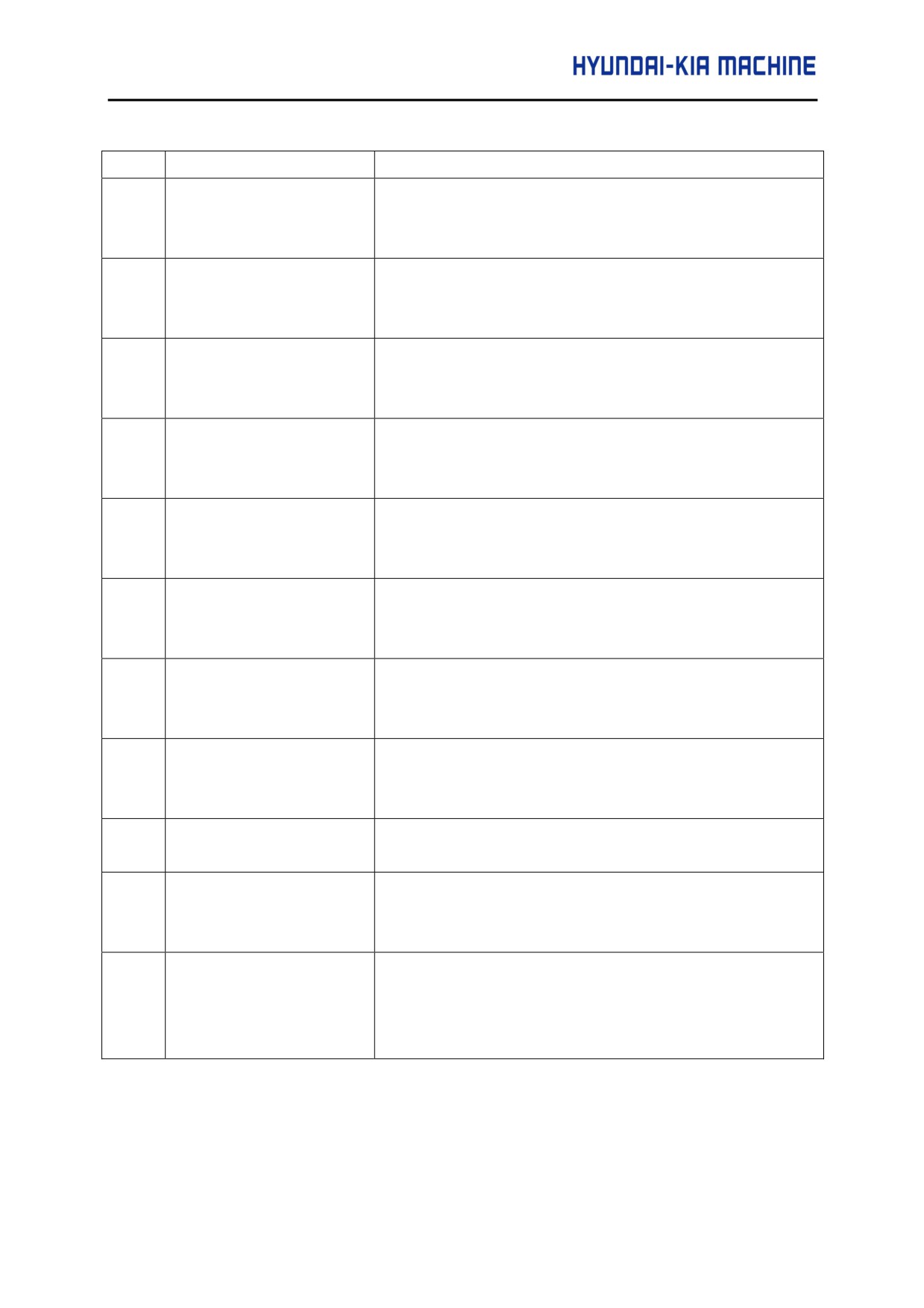
4830
ZONE: ENTERING
When a safety zone check was executed, the machine moving
INHIBITED 1+Y
in the positive Y direction entered area 1 into which entry is
inhibited.
4831
ZONE: ENTERING
When a safety zone check was executed, the machine moving
INHIBITED 1-Y
in the negative Y direction entered area 1 into which entry is
inhibited.
4832
ZONE ENTERING
When a safety zone check was executed, the machine moving
INHIBITED 2+Y
in the positive Y direction entered area 2 into which entry is
inhibited.
4833
ZONE: ENTERING
When a safety zone check was executed, the machine moving
INHIBITED 2-Y
in the negative Y direction entered area 2 into which entry is
inhibited.
4834
ZONE ENTERING
When a safety zone check was executed, the machine moving
INHIBITED 3+Y
in the positive Y direction entered area 3 into which entry is
inhibited.
4835
ZONE: ENTERING
When a safety zone check was executed, the machine moving
INHIBITED 3-Y
in the negative Y direction entered area 3 into which entry is
inhibited.
4836
ZONE ENTERING
When a safety zone check was executed, the machine moving
INHIBITED 4+Y
in the positive Y direction entered area 4 into which entry is
inhibited.
4837
ZONE: ENTERING
When a safety zone check was executed, the machine moving
INHIBITED 4-Y
in the negative Y direction entered area 4 into which entry is
inhibited.
4870
AUTO SETTING FEED
The feed rate of safety zone auto setting is other than the
ERROR
parameter value (No.16538, No.16539)
4841
AUTO SETTING PIECES
In safety zone auto setting, the safety zone pieces are not
ERROR
correct. Or the position detector has gone wrong, please tell
your machine tool builder.
4872
AUTO SETTING
M code, S code or T code is specified with safety zone auto
COMMAND ERROR
setting command (G32). G32 is specified in the nibbling mode,
in the cutter compensation, in the rotation mode or the scaling
mode.
5-143
13) System alarms
(These alarms cannot be reset with reset key)
No.
Message
Contents
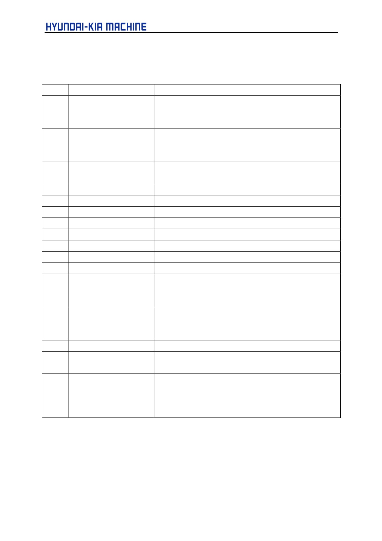
900
ROM PARITY
A parity error occurred in the CNC, macro, or servo ROM.
Correct the contents of the flash ROM having the displayed
number
910
SRAM PARITY:(BYE 0)
A RAM parity error occurred in the part program storage RAM.
Clear the RAM, or replace the SRAM module or motherboard.
Subsequently, re-set the parameters and all other data.
911
SRAM PARITY:(BYE 1)
A RAM parity error occurred in the DRAM module. Replace
the.DRAM module.
912
DRAM PARITY:(BYE 0)
913
DRAM PARITY: (BYE 1)
914
DRAM PARITY:(BYE 2)
915
DRAM PARITY: (BYE 3)
916
DRAM PARITY: (BYE 4)
917
DRAM PARITY:(BYE 5)
918
DRAM PARITY: (BYE 6)
919
DRAM PARITY: (BYE 7)
920
SERVO ALARM(1-4AXIS)
Servo alarm (first to fourth axis). A watchdog alarm condition
occurred, or a RAM parity error occurred in the axis control
card. Replace the axis control card.
921
SERVO ALARMI5-8AXIS)
Servo alarm (first to fourth axis). A watchdog alarm condition
occurred, or a RAM parity error occurred in the axis control
card. Replace the axis control card.
926
FSSB ALARM
FSSB alarm. Replace the axis control card.
930
CPU INTERRUPT
CPU error (abnormal interrupt). The motherboard or CPU card
may be faulty.
935
SRAM ECC ERROR
An error occurred in RAM for part program storage. Action :
Replace the master printed circuit board
(SRAM module),
perform all-clear operation, and set all parameter and other
data other again.
5-144

V. REPAIR AND PRESERVATION
No.
Message
Contents
950
PMC SYSTEM ALARM
An error occurred in the PMC. For details of PC xxx, see the list
PC xxx
of system alarm messages in Section A.2, "LIST OF ALARMS
YYYYYYYYYYYYYY
(PMC)" in this manual.
951
PMC WATCH DOG ALARM
An error occurred in the PMC.
(Watchdog alarm)
The motherboard may be faulty.
970
NMI OCCURRED IN
With the PMC-SA1, an error occurred in the control LSI device
PMCLSI
on the motherboard. (I/O parity). Replace the motherboard
PMC RAM
971
NMI OCCURRED IN SLC
With the PMC-SA1, an I/O Link disconnection was detected.
Check the I/O Link.
972
NMI OCCURRED IN
An NMI occurred on a board other than the motherboard. The
OTHER MODULE
option board may be faulty.
973
NON MASK INTERRUPT
An NMI occurred as a result of an unknown cause.
974
F-BUS ERROR
A bus error occurred on the FANUC bus.
The motherboard or option board may be faulty.
975
BUS ERROR
A bus error occurred on the motherboard.
The motherboard may be faulty.
976
L-BUS ERROR
A bus error occurred on the local bus.
The motherboard may be faulty.
5-145
APPENDIX
1.
Spindle Amplifier Module
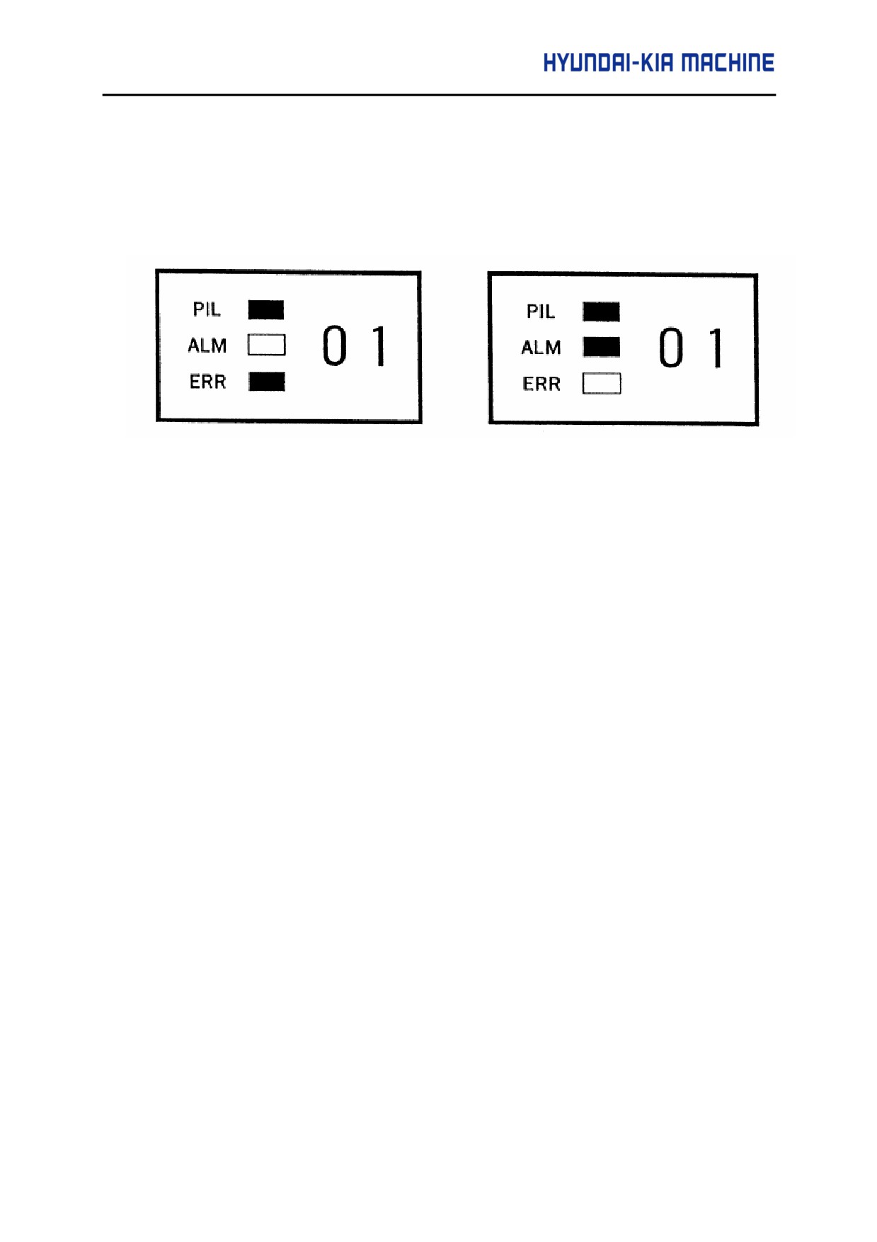
If an alarm occurs in the spindle amplifier module, the ALM LED lights red in the STATUS display,
and the two-digit 7-segment LEDs indicate the alarm code.
<Error No. 01>
<Alarm No. 01>.
1-1. Alarm A0. A1
(1) Meaning
The control program is not running.
(2) Cause and corrective action
a) ROM installed improperly or yet to be installed.
Make sure that the ROM is attached properly to the socket and there is no imperfect
contact due to a broken or bent pin.
⇒ Install the ROM properly.
b) Incorrect ROM installed
The series number of the software is printed on the ROM package and is displayed at
power-on.
⇒ Replace it with the correct ROM.
c) Printed-circuit board defective
⇒ Replace it with a normal printed circuit board.
1-2. Alarm AL-01
(1) Meaning
The temperature inside the motor is higher than the rating.
(2) Cause and corrective action
a) Over loaded operation
Check the cutting conditions, the state of the cutting tool, and the load meter reading
A-1
during cutting.
⇒ Examine the cutting conditions and the tool.
b) The cooling fan inside the motor is defective. Check whether the cooling fan rotates
smoothly.
⇒ Replace the cooling fan.
c) The motor cooling system is dirty.
⇒ Clean the cooling system with a vacuum cleaner or the factory air blower.
d) Motor overheat signal wire discontinued or loosely connected Check the motor overheat
signal wire for secure connection.
⇒ Connect the signal wire properly.
e) Invalid detector parameter setting Check the detector and its parameters.
⇒ Set the parameters that match the detector correctly.
f)
Motor or thermostat defective =s> Replace the motor.
1-3. Alarm AL-02
(1) Meaning
The actual motor speed is largely deviated from the commanded speed.
(2) Cause and corrective action
a) Over loaded operation or too heavy load.
Check the load meter to see if the load is too heavy.
⇒ Examine the cutting conditions and the tool again.
b) Abnormal power line connect
Check the power line for disconnection or poor contact.
⇒ Connect the power line properly.
c) Incorrect acceleration/deceleration duration parameter setting.
Check the parameter setting and the actual acceleration/deceleration duration.
FS 0i/16/18/21
Description
4082
Acceleration/deceleration duration setting
A-2
APPENDIX
⇒ Set the parameter with a value somewhat greater (margin) than the required
acceleration/deceleration duration.
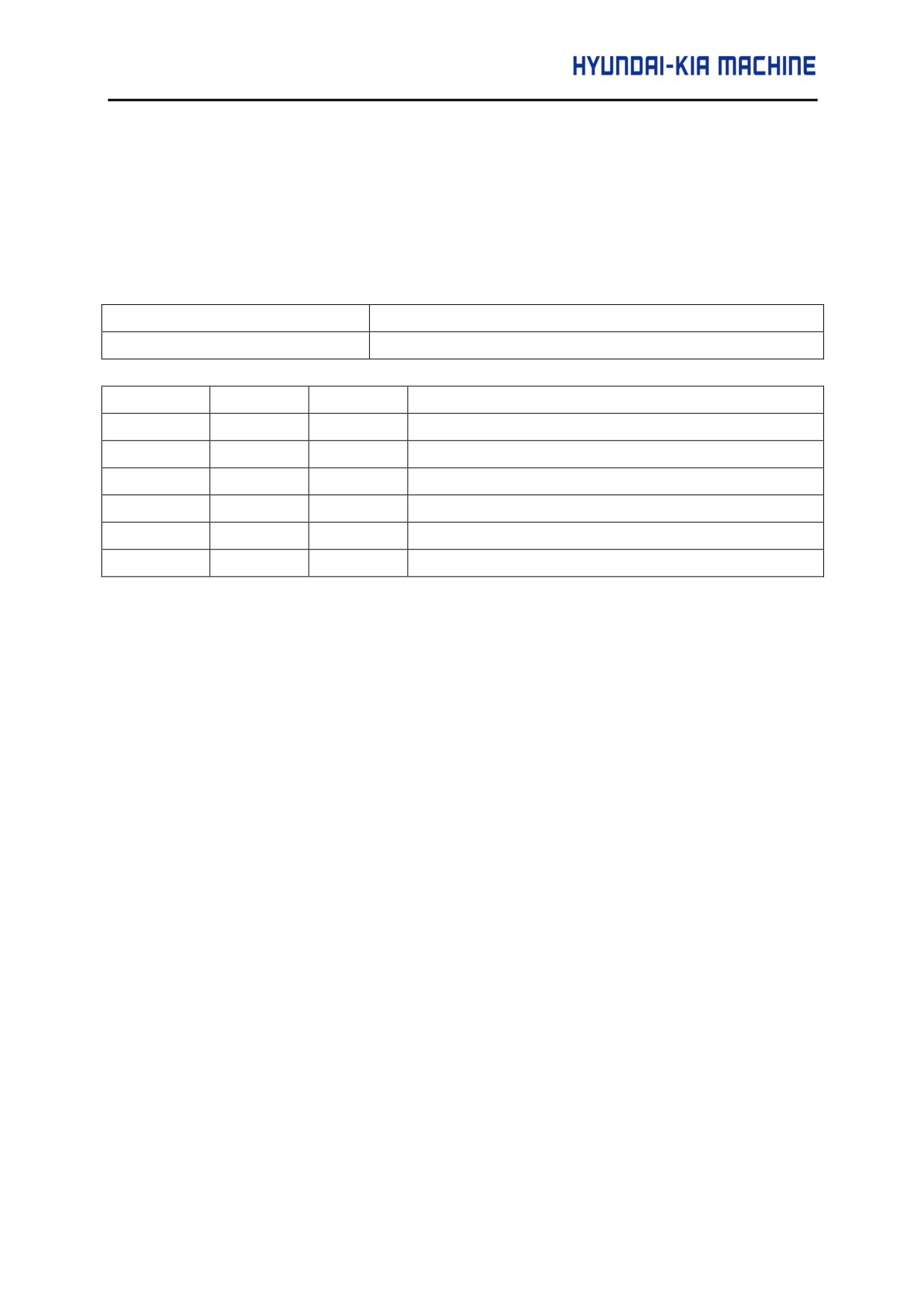
d) Incorrect speed detector parameter setting
Check the parameter setting and the speed detector.
FS 0i/16/18/21
Description
4011 #2, 1, 0
Speed detector setting
VDT3
VDT2
VDT1
Speed detector setting
0
0
0
64λ/ rev
0
0
1
128 λ/ rev
0
1
0
256λ/ rev
0
1
1
512λ/ rev
1
0
0
192λ/ rev
1
0
1
384λ/ rev
⇒ Set the parameter correctly according to the speed detector.
e) IGBT module/IPM defective Replace the IGBT module/IPM.
f)
Speed feedback signal faulty
Check the speed feedback signal level.
⇒ Check the speed detector. Also check the signal cable for continuity.
1-4. Alarm AL-03
(1) Meaning
The fuse at the DC link has blown.
(2) Cause and corrective action
a) Overcurrent flowed in the main circuit.
A-3
Check the IGBT module/IPM. If the IGBT module/IPM is defective, it allows
overcurrent to flow in the main circuit.
⇒ Replace the fuse and/or IGBT module/IPM.
1-5. Alarm AL-07
(1) Meaning
The actual motor speed exceeded 115% of the maximum allowable motor speed (standard
parameter setting). Cause and corrective action.
a) Incorrect speed detector parameter setting.
Check the parameter setting and the speed detector.
FS 0I/16/18/21
Description
4011 #2, 1, 0
Speed detector setting
⇒ Set the parameter correctly according to the speed detector.
1-6. Alarm AL-09
(1) Meaning
The temperature of the main circuit heat sink has risen abnormally.
(2) Cause and corrective action
a) Cooling fan defective
Check whether the cooling fan rotates smoothly.
⇒ Replace the cooling fan.
b) Overloaded operation
Check the load meter to see if the load is too heavy.
⇒ Examine the cutting conditions again.
c) Cooling fan clogged
⇒ Clean the cooling fan with a vacuum cleaner or the factory air blower.
A-4
APPENDIX
1-7. Alarm AL-12
(1) Meaning
Excessive current flowed in the DC section (DC link) of the main circuit. The main circuit
power module (IPM) detected an error.
(2) Cause and corrective action
a) Short-circuit between the amplifier output terminals or inside the motor Check the power
line connection for a short-circuit.
⇒ Make a correct connection. Replace the motor if it is defective.
b) IGBT(or IPM) defective
Replace the IGBT(or IPM).
c) Printed circuit board defective
⇒ Replace the printed circuit board.
d) Incorrect model-specific parameters.
Check the model-specific parameter settings with the model specific parameter list.
⇒ Set the parameters with the values that match the motor used.
1-8. Alarm AL-13
(1) Meaning
The memory inside the CPU is abnormal when power is switched on.
(2) Cause and corrective action
a) Printed-circuit board defective
⇒ Replace the printed circuit board.
1-9. Alarm AL-15
(1) Meaning
A sequence of switching operations was incorrect during speed range switching control or
spindle switching control. Cause and corrective action.
A-5
(2) Cause and corrective action
a) Switching unit
(magnetic contactor for power line switching) defective Check the
operation of the switching unit.
⇒ Replace the switching unit.
b) Loose contact of the magnetic contactor state signal (auxiliary contact signal) Make
sure that the magnetic contactor state signal is switched properly.
⇒ Connect the magnetic contactor correctly.
c) Improper sequence
⇒ Adjust the switching unit for the correct sequence.
1-10.
Alarm AL-16
(1) Meaning
The memory (RAM) is abnormal. It is checked when power is switched on.
(2) Cause and corrective action
a) Printed-circuit board defective
⇒ Replace the printed-circuit board.
1-11.
Alarm AL-19
(1)
Meaning
The offset voltage for the phase U current detection circuit is too high. This check is made
when power is switched on.
(2) Cause and corrective action
a) Loose contact of the printed-circuit board
Check that the printed-circuit board is connected to the power circuit securely.
⇒ Connect the printed-circuit board securely.
b) Phase U current detection circuit defective.
⇒ Replace the printed-circuit board.
c) A/D converter defective
⇒ Replace the printed-circuit board.
A-6
APPENDIX
1-12.
Alarm AL-20
(1) Meaning
The offset voltage for the phase V current detection circuit is too high. This check is made when
power is switched on.
(2) Cause and corrective action
a) Loose contact of the printed-circuit board
Check that the printed-circuit board is connected to the power circuit securely.
⇒ Connect the printed-circuit board securely.
b) Phase V current detection circuit defective.
⇒ Replace the printed-circuit board.
1-13.
Alarm AL-24
(1) Meaning
The serial communication data between the CNC and spindle amplifier is abnormal. (This
alarm occurs also when the CNC power is switched off.)
(2) Cause and corrective action
a) The CNC power is off.
⇒ Switch on the CNC power.
b) Serial communication cable defective
Check the connection of the cable. Also check for a broken wire.
⇒ Connect the cable correctly. If any wire in the cable is broken, replace it.
c) Serial communication LSI chip defective
⇒ Replace the LSI chip or the printed-circuit board with the LSI on it.
d) I/O link adapter defective (if used)
⇒ Replace the I/O link adapter.
1-14.
Alarm AL-25
(1) Meaning
Serial communication between the CNC and the spindle amplifier has stopped.
A-7
(2) Cause and corrective action
a) Serial communication cable defective
Check the connection of the cable. Also check for a broken wire.
⇒ Connect the cable correctly. If any wire in the cable is broken, replace it.
b) Serial communication LSI chip defective
⇒ Replace the printed-circuit board.
1-15.
Alarm AL-26
(1)
Meaning
The Cs contouring control speed detection signal (detector on the motor sid(e) is abnormal.
(2)
Cause and corrective action
a) Feedback signal level insufficient
Check the connection of the cable. Also check for a broken wire.
⇒ Connect the cable correctly. If any wire in the cable is broken, replace it.
b) Feedback signal level insufficient
Check the feedback signal level with an oscilloscope.
⇒ Adjust so that the feedback signal level becomes the rated value.
c) Feedback signal cable not shielded properly (circuit malfunction due to noise) Check
whether the cable is shielded properly.
⇒ Shield it correctly.
d) Detection circuit defective
⇒ Replace the parameter-circuit board.
e) Incorrect parameter setting
Check the parameter setting for use of the Cs contouring control detector.
FS 0I/16/18/21
Description
4011 #5
Parameter set to specify use of the Cs contouring control
detector.
⇒ Set the parameter correctly according to the detector used.
A-8
APPENDIX
1-16.
Alarm AL-27
(1) Meaning
Position coder signal error
(2) Cause and corrective action
a)
Feedback signal cable defective
Check the connection of the cable. Also check for a broken wire.
⇒ Connect the cable correctly. If any wire in the cable is broken, replace it.
b)
Position coder defective Check the position coder signal.
⇒ Replace the position coder.
c)
Feedback signal level insufficient (for built in sensor or the high resolution magnetic pulse
coder)
Check the feedback signal level with an oscilloscope.
⇒ Adjust so that the feedback signal level becomes the rated value.
d)
Feedback signal cable not shielded properly (circuit malfunction due to nois(e) Check
whether the cable is shielded properly.
⇒ Shield it correctly.
e)
Detection circuit defective
⇒ Replace the printed-circuit board.
f)
Incorrect parameter setting
Check the parameter set to specify use of the Cs contouring control detector.
FS 0I/16/18/21
Description
4011 #2
Parameter set to specify use of the Cs contouring control
detector.
⇒ Set the parameter correctly according to the detector used.
1-17. Alarm AL-28
(1) Meaning
The Cs contouring control speed detection signal
(detector on the spindle sid(e) is
A-9
abnormal.
(2)
Cause and corrective action
a)
Feedback signal level insufficient
Check the connection of the cable. Also check for a broken wire.
⇒ Connect the cable correctly. If any wire in the cable is broken, replace it
b)
Feedback signal level insufficient
Check the feedback signal level with an oscilloscope.
⇒ Adjust so that the feedback signal level becomes the rated value.
c)
Feedback signal cable not shielded properly (circuit malfunction due to nois(e).
Check whether the cable is shielded properly.
⇒ Shield it correctly.
d)
Detection circuit defective
⇒ Replace the printed-circuit board.
e)
Incorrect parameter setting
Check the parameter set to specify use of the Cs contouring control detector.
FS 0I/16/18/21
Description
4011 #2
Parameter set to specify use of the Cs contouring control
detector.
⇒ Set the parameter correctly according to the detector used.
1-18.
Alarm AL-29
(1)
Meaning
Excessive load (at least 90% of the maximum output as set initially by a parameter)
was applied continuously for a certain
(2)
Cause and corrective action
a)
Overloaded operation, or too heavy load
Check the load meter to see if the load is too heavy.
⇒ Examine the cutting conditions and the tool again.
A-10
APPENDIX
1-19. Alarm AL-31
(1)
Meaning
The motor cannot rotate at a specified speed. It rotates at very low speed, or even
stops.
(2)
Cause and corrective action
a)
Motor locked.
Check whether the motor cannot accelerate because it is physically locked.
⇒ Remove the cause.
b)
Motor speed feedback cable defective
Check the connection of the cable. Also check for a broken wire.
⇒ Connect the cable correctly. If any wire in the cable is broken, replace it
c)
Motor speed feedback signal abnormal
Check the speed feedback signal with an oscilloscope.
⇒ Adjust so that the feedback signal level becomes the rated value.
d)
Incorrect power line wire connection
Check the connection of the power line wires (for phase order, etc.)
⇒ Connect the power line correctly.
1-20. Alarm AL-32
(1)
Meaning
The memory in the serial communication LSI chip is abnormal. It is checked when
power is turned on.
(2)
Cause and corrective action a) LSI chip defective
⇒ Replace the printed-circuit board.
1-21. Alarm AL-34
(1)
Meaning
The parameter setting is invalid.
A-11
(2)
Cause and corrective action
a)
Incorrect parameter setting Check the parameter setting
⇒ Set the parameter with a valid value.
1-22. Alarm AL-35
(1)
Meaning
The value set in the gear ratio data parameter is greater than the limit allowed in the
internal processing.
(2)
Cause and corrective action
a)
Incorrect gear ratio parameter setting
Check whether the specified gear ratio is too high.
FS 0I/16/18/21
Description
4056 ~ 4059
Spindle to motor gear ratio data
⇒ Use the appropriate value.
1-23. Alarm AL-36
(1)
Meaning
The error counter overflowed.
(2)
Cause and corrective action
a)
Incorrect parameter setting
Check whether the values set in the gear ratio and position gain parameters are too
large.
⇒ Use the appropriate values.
A-12
APPENDIX
FS 0I/16/18/21
Description
4056 ~ 4059
Spindle to motor gear ratio data
4060 ~ 4063
Position gain during orientation
4065 ~ 4068
Position gain during servo mode/ synchronization control of
the spindle
4069 ~ 4072
Position gain during Cs contouring control
1-24.
Alarm AL-37
(1)
Meaning
When an emergency stop signal was entered, the motor did not decelerate, rather
accelerate, or the motor was kept excited even after acceleration/deceleration duration
(10 seconds as set initially by a parameter).
(2)
Cause and corrective action
a)
Incorrect speed detector parameter setting
Check the parameter setting and the speed detector.
FS 0I/16/18/21
Description
4011 #2, 1, 0
Speed detector setting
⇒ Set the parameter to the value that matches the speed detector used.
b)
Incorrect acceleration/deceleration duration parameter setting
Check the parameter setting with the required deceleration time.
FS 0I/16/18/21
Description
4082
Acceleration/deceleration duration setting
⇒ Set the parameter with a value somewhat greater (margin) than the required deceleration duration.
A-13
1-25. Alarm AL-39
(1)
Meaning
The Cs contouring control one-rotation signal has not been detected correctly.
(2)
Cause and corrective action
a)
Feedback signal cable not shielded properly
Check whether there is noise on the feedback signal.
Also check whether the cable is shielded properly.
⇒ Shield it correctly.
b)
Feedback signal level insufficient
Check the feedback signal level with an oscilloscope.
⇒ Adjust so that the feedback signal level becomes the rated value.
(c)
Incorrect parameter setting
Check the parameter correctly according to the detector used.
FS 0I/16/18/21
Description
4003#7,6,4
Parameter set to specify use of the Cs contouring control
detector.
⇒ Set the parameter correctly according to the detector used.
d)
Detection circuit defective
⇒ Replace the printed-circuit board.
1-26. Alarm AL-40
(1)
Meaning
The Cs contouring control one rotation signal is not generated.
(2)
Cause and corrective action
a)
Feedback signal cable defective Check the connection of the cable.
⇒ Connect the cable correctly.
A-14