Hyundai SKT 100/200 CNC TURNING CENTER. INSTALLATION MAINTENANCE MANUAL (VERSION No.: VOL1.0) - page 7
Maintenance Instruction Related To Fanuc Spindle Alarm
When a serial spindle alarm occurs, the following number is displayed on the CNC. n is a number
corresponding to the spindle on which an alarm occurs. (n = 1 : First spindle: n = 2 : Second spindle;
etc.)
Note
Note that the meanings of the SPM indications differ depending on which LED, the red or yellow LED, is
on. When the red LED is on, the SPM indicates a 2-digit alarm number. When the yellow LED is on, the
SOM indicates an error number that designates a sequence problem (for emergency stop state not
released).
SPM
indication
Faulty location and remedy
Description
(*1)
A0 A
1 Replace the ROM on the SPM control
The program does not start normally. ROM
printed circuit board.
series error or hardware abnormality on the
2 Replace the SPM control printed circuit
SPM control printed circuit board.
board.
A1
Replace the SPM control printed circuit
An abnormality was detected in the CPU
board.
peripheral circuit of the SPM control circuit.
01
1 Check and correct the peripheral
The thermostat embedded in the motor
temperature and load status.
winding
operated.
The
internally
2 If the cooling fan stops, replace it.
temperature of the motor exceeds the
specified level. The motor is used in excess
of the continuous rating, or the cooling
component is abnormal.
02
1 Check and correct the cutting
The motor speed cannot follow a specified
conditions to decrease the load.
speed. An excessive motor load torque is
2 Correct parameter No.4082.
detected. The acceleration/deceleration
time in parameter No.4082 is insufficient.
5-100
V. REPAIR AND PRESERVATION
SPM
indication
Faulty location and remedy
Description
(*1)
03
1 Replace the SPM unit.
The PSM becomes ready (00 is indicated),
2 Check the motor insulation status.
but the DC link voltage is to low in the SPM.
3 Replace the interface cable.
The fuse in the DC link voltage is too low in
the SPM is blown. (The power device is
damaged or the motor is groundfault). The
JX1A/JX1B connection cable is abnormal.
04
Check the state of the input power supply
The PSM found a missing power supply
to the PSM.
phase. (SPM alarm 5)
06
1 Check and correct the parameter.
The temperature sensor of the motor is
2 Replace the feedback cable.
disconnected.
07
Check for a sequence error. (For example,
The motor speed has exceeded 115% of its
check whether spindle synchronization was
rated speed. When the spindle axis was in
specified when the spindle could not be
position control mode, positional deviations
turned.)
were accumulated excessively
(SFR and
SRV were turned off during spindle
synchronization.)
09
1 Improve the heat sink cooling status.
Abnormal temperature rise of the power
2 If the heat sink cooling fan stops,
transistor radiator
replace the SPM unit.
11
1 Check the selected PSM.
Overvoltage of the DC link section of the
2 Check the input power voltage and
PSM was detected. (PSM alarm indication:
change in power during motor
7) PSM selection error.(The maximum
deceleration. If the voltage exceeds
output specification of the PSM is
253 VAC (for the 200-V system) or 530
exceeded).
VAC (for the 400-V system), improve
the power supply impedance.
12
1 Check the motor insulation status.
The motor output current is abnormally high.
2 Check the spindle parameters.
A motor-specific parameter does not match
3 Replace the SPM unit
the motor model. Poor motor insulation.
5-101
SPM
Faulty location and remedy
Description
indication
(*1)
15
1 Check and correct the ladder sequence.
The switch sequence in spindle switch/output
2 Replace the switching MC.
switch operation is abnormal. The switching
MC contact status check signal and
command do not match.
16
Replace the SPM control printed circuit
Abnormality in an SPM control circuit
board.
component is detected. (RAM for external
data is abnormal.)
18
Replace the SPM control printed circuit
Abnormality in an SPM control circuit
board.
component is detected. (Program ROM data
is abnormal.)
19
Replace the SPM unit.
Abnormality in an SPM component is
detected. (The initial value for the U phase
current detection circuit is abnormal.)
20
Replace the SPM unit.
Abnormality in an SPM component is
detected. (The initial value of the V phase
current detection circuit is abnormal.)
21
Check and correct the parameters.
The polarity parameter setting of the position
(No.4000#0, 4001 #4)
sensor is wrong.
24
1 Place the CNC-to-spindle cable away
The CNC power is turned off
(normal
from the power cable.
power-off or broken cable). An error is
2 Replace the cable
detected in communication data transferred
to the CNC.
26
1 Replace the cable. 2 Re-adjust the BZ
The signal amplitude of the detection signal
sensor signal.
(connector JY2) on the Cs contour control
motor side is abnormal. (Unconnected cable,
adjustment error, etc.)
27
1 Replace the cable.
2 Re-adjust the
1 The spindle position coder
(connector
pre-amplifier.
JY4) signal is abnormal.
2 The signal amplitude (connector JY2)of
the MZ or BZ sensor is abnormal
(Unconnected cable, adjustment error,
etc.)
5-102
V. REPAIR AND PRESERVATION
SPM
Faulty location and remedy
Description
indication
(*1)
28
1 Replace the cable.
The position detection signal
(connector
2 Re-adjust the BZ sensor signal.
JY5)for Cs contour control is abnormal.
(Unconnected cable, adjustment error, etc.)
29
Check and correct the load status.
Excessive load has been applied
continuously for a certain period of time. (This
alarm is issued also when the motor shaft has
been locked in the excitation state.)
30
Check and correct the power supply
Overcurrent is detected in PSM main circuit
voltage.
input. (PSM alarm indication : 1) Unbalanced
power supply.
PSM selection error (The maximum PSM
output specification is exceeded.)
31
1 Check and correct the load status.
The motor cannot rotate at a specified speed.
2 Replace the motor sensor cable (JY2 or
(A level not exceeding the SST level for the
JY5).
rotation command has existed continuously.)
Abnormality in the speed detection signal.
32
Replace the SPM control printed circuit
Abnormality in an SPM control circuit
board.
"component is detected. (The LSI device for
serial transfer is abnormal.)
33
Check and correct the power supply
Charging of direct current power supply
voltage.
voltage in the power circuit section is
2 Replace the PSM unit.
insufficient when the magnetic contractor in
the amplifier is turned on
(such as open
phase and defective charging resistor).
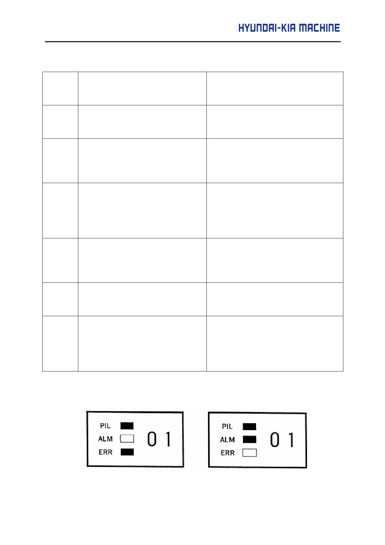
<LED display on the AMP during spindle alarm and error>
(Error No.01)
(Alarm No.01)
5-103
3-9-7. Alarm List
(1) Program errors (P/S alarm)
No.
Message
Contents
000
PLEASE TURN OFF
A parameter which requires the power off was input, turn off power.
POWER
001
TH PARITY ALARM
TH alarm (A character with incorrect parity was input). Correct the tape.
002
TV PARITY ALARM
TV alarm (The number of characters in a block is odd). This alarm will be
generated only when the TV check is effective.
003
TOO MANY DIGITS
Data exceeding the maximum allowable number of digits was input
(Refer to the item of max. programmable dimensions).
004
ADDRESS
NOT
A numeral or the sign "-" was input without an address at the beginning of
FOUND
a block. Modify the program.
005
NO DATA AFTER
The address was not followed by the appropriate data but was followed
ADDRESS
by another address or EOB code. Modify the program.
006
ILLEGAL USE OF
Sign "-" input error (Sign "-" was input after an address with which it
NEGATIVE SIGN
cannot be used. Or two or more "-" signs were input). Modify the
program.
007
ILLEGAL USE OF
Decimal point "-" input error (A decimal point was input after an address
DECIMAL POINT
with which it can not be used. Or two decimal points were input). Modify
the program.
009
ILLEGAL ADDRESS
Unusable character was input in significant area. Modify the program.
INPUT
010
IMPROPER G-CODE
An unusable G code or G code corresponding to the function not
provided is specified. Modify the program.
5-104
V. REPAIR AND PRESERVATION
No.
Message
Contents
011
NO
FEEDRATE
Feedrate was not commanded to a cutting feed or the feedrate was
COMMANDED
inadequate. Modify the program.
014
ILLEGAL
LEAD
In variable lead threading, the lead incremental and decremental
COMMAND
out-putted by address K exceed the maximum command value or
command such that lead becomes a negative value is given. Modify the
program.
015
TOO MANY AXES
An attempt has been made to move the tool more than the maximum
COMMAND
number of simultaneously controlled axes. Alternatively, no axis
movement command or an axis movement command for two or more
axes has been specified in the block containing the command must be
accompanied with an axis movement command for a single axis, in the
same block.
020
OVER TOLERANCE
In circular interpolation
(G20 or G30), difference of the distance
OF RADIUS
between the start point and the enter of an arc and that between the end
point and the center of the arc exceeded the value specified in
parameter No.3410.
021
ILLEGAL
PLANE
An axis not included in the selected plan (by using G17, G18, G19) was
AXIS COMMANDED
command in circular interpolation. Modify the program.
022
CIRCULAR
In circular interpolation, radius R, or the distance between the start point
INTERPOLATION
and the center of the arc, I, J, or K, has not been specified.
020
G NO CIRCLE
When circular interpolation is specified, neither R (specifying an arc
RADIUS
radius), or I, J, and K (specifying the distance from a start point to the
center) is specified.
023
ILLEGAL RADIUS
In circular interpolation by radius designation, negative value was
COMMAND
commanded for address R. Modify the program.
028
ILLEGAL
PLANE
In the plane selection command, two or more axes in the same direction
SELECT
are commanded. Modify the program.
029
ILLEGAL OFFSET
The offset values specified by T code is too large. Modify the program.
VALUE
030
ILLEGAL OFFSET
The offset number in T function specified for tool offset s too large.
NUMBER
Modify the program
5-105
No.
Message
Contents
031
ILLEGAL
P
In setting an offset amount by G10, the offset number following address
COMMAND IN G10
P was excessive of it was not specified. Modify the program.
032
ILLEGAL OFFSET
In setting an offset amount by G10 or in writing an offset amount by
VALUE IN G10
system variables, the offset amount was excessive.
033
NO SOLUTION AT
A point of intersection cannot be determined for tool nose radius
NRC
compensation. Modify the program.
034
NO CIRC ALLOWED
The start up or cancel was going to be performed in the G02 or G03
IN ST-UP/EXT BLK
mode in tool nose radius compensation. Modify the program.
035
CAN
NOT
Skip cutting (G31) was specified in tool nose radius compensation
COMMAND G31
mode. Modify the program.
037
CAN NOT CHANGE
The offset plane is switched in tool nose radius compensation. Modify
PLANE IN NRC
the program.
038
INTERFERENCE IN
Overcutting will occur in tool nose radius compensation because the arc
CIRCULAR BLOCK
start point or end point coincides with the arc center. Modify the
program.
039
CHF/CNR
NOT
Chamfering or corner R was specified with a start-up, a cancel, or
ALLOWED IN NRC
-switching between G41 and G42 in tool nose radius compensation.
The program may cause overcutting to occurs in chamfering or corner
R. Modify the program.
040
INTERFERENCE IN
Overcutting will occur in tool nose radius compensation in canned cycle
G90/94 BLOCK
G90 or G94. Modify the program. Modify the program.
041
INTERFERENCE IN
Overcutting will occur in tool nose radius compensation. Modify the
NRC
program.
046
ILLEGAL
Other than P2. P3 and P4 are commanded for 2nd, 3rd and 4th
REFERENCE
reference position return command.
RETURN
COMMAND
047
ILLEGAL
AXIS
Two or more paralled axes (in parallel with a basic axis) have been
SELECT
specified upon start-up of three-dimensional tool compensation or
three-dimensional coordinate conversion.
048
BASIC 3 AXIS NOT
Start-up of three-dimensional tool compensation or three-dimensional
FOUND
coordinate conversion has been attempted, but the three basic axes
used when Xp, Yp, or Zp is omitted are not set in parameter No. 1022.
5-106
V. REPAIR AND PRESERVATION
No.
Message
Contents
050
CHF/CNR
NOT
Chamfering or corner R is commanded in the thread cutting block.
ALLOWED IN THRD
Modify the program.
BLK
051
MISSING
MOVE
Improper movement or the move distance was specified in the block
AFTER CHF/CNR
next to the chamfering or corner R block. Modify the program.
052
CODE IS NOT G01
The block next to the chamfering or corner R block in not G01. Modify
AFTER CHF/CNR
the program.
053
TOO
MANY
In the chamfering and corner R commands, two or more of I, K and R
ADDRESS
are specified. Otherwise, the character after a comma (",") is not C or R
COMMANDS
in direct drawing dimensions programming. Modify the program.
054
NO
TAPER
A block in which chamfering in the specified angle or the corner R was
ALLOWED AFTER
specified includes a taper command. Modify the program.
CHF/CNR
055
MISSING
MOVE
In chamfering or corner R block, the move distance is less than chamfer
VALUE IN CHF/CNR
or corner R amount.
056
NO END POINT &
Neither the end point or angle is specified in the command for the block
ANGLE IN CHF/CNR
next to that for which only the angle is specified(A). In the chamfering
command. I(K) is commanded for the X(Z) axis.
057
NO SOLUTION OF
Block end point is not calculated correctly in direct dimension drawing
BLOCK END
programming.
058
ND POINT NOT
Block end point is not found in direct dimension drawing programming.
FOUND
059
PROGRAM
In an external program number search or external workpiece number
NUMBER
NOT
search, a specified program number was not found. Otherwise, a
FOUND
program specified for searching is being edited in background
processing. Check the program number and external signal. Or
discontinue the background editing.
5-107
No.
Message
Contents
060
SEQUENCE NUMBER
Commanded sequence number was not found in the sequence number
NOT FOUND
search. Check the sequence number.
061
ADDRESS P/Q NOT
Address P or Q is not specified in G70, G71, G72, or G73 command.
FOUND IN G70-G73
Modify the program.
062
ILLEGAL COMMAND
1. The depth of cut in G71 or G72 is zero or negative vale.
IN G71-G76
2. The repetitive count in G73 is zero or negative vale.
3. The negative value is specified to U i or U k is zero in G74 or G75.
4. A value" other than zero is specified to address U or W, though U I
or U k is zero in G74 or G75.
5. A negative value is specified to Ud, thought the relief direction in
G74 or G75 is determined.
6. Zero or a negative value is specified to the height of thread or depth
of cut of first time in G76.
7. The specified minimum depth of cut in G76 is greater than the height
of thread.
8. An unusable angle of tool tip is specified in G76. Modify the
program.
063
SEQUENCE
The sequence number specified by address P in G70, G71, G72, or
NUMBER NOT
G73 command cannot be searched. Modify the program.
FOUND
064
SHAPE PROGRAM
A target shape which is not monotonous increase or decrease was
NOT MONO-
specified in a repetitive canned cycle (G71 or G72).
TONOUSLY
065
ILLEGAL COMMAND
1. G00 or G01 is not commanded at the block with the sequence
IN G71-G73
number which is specified by address P in G71, G72, or G73
command.
2. Address Z(W) or X(U) was commanded in the block with a sequence
number which is specified by address P in G71 or G72, respectively.
Modify the program.
066
IMPROPER G-CODE
An unallowable G code was commanded between two blocks specified
IN G71-G73
by address P in G71, G72, or G73. Modify the program.
5-108
V. REPAIR AND PRESERVATION
No.
Message
Contents
067
CAN NOT OPERATE
G70, G71, G72, or G73 command with address P and Q was
IN MDI MODE
specified. Modify the program.
069
FORMAT ERROR IN
The final move command in the blocks specified by P and Q of G70,
G70-G73
G71, G72, or G73 ended with chamfering or corner R.
070
NO PROGRAM
The memory area is insufficient. Delete any unnecessary program,
SPACE IN MEMORY
then retry.
071
DATA NOT FOUND
The address to be searched was not found, or the program with
specified program number was not found in program number search.
Check the data.
072
TOO MANY
The number of programs to be stored exceeded
63(basic),
PROGRAMS
125(option),
200(option),
400(option), or
1000
(option). Delete
unnecessary programs and execute program registration again.
073
PROGRAM NUMBER
The commanded program number has already been used. Change
ALREADY IN USE
the program number or delete unnecessary programs and execute
program registration again.
074
ILLEGAL PROGRAM
The program number is other than 1 to 9999. Modify the program
NUMBER
number.
075
PROTECT
An attempt was made to register a program whose number was
protected.
076
ADDRESS P NOT
Address P (program number) was not commanded in the block which
DEFINED
includes an M98, G65, or G66 command. Modify the program.
077
SUB
PROGRAM
The subprogram was called in five folds. Modify the program.
NESTING ERROR
5-109
No.
Message
Contents
078
NUMBER NOT
A program number or a sequence number which was specified by
FOUND
address P in the block which includes an M98, M99, G66 was not
found. The sequence number specified by a GOTO statement was not
found. Otherwise, a called program is being edited in background
processing. Correct the program, or discontinue the back-ground
editing.
079
PROGRAM VERIFY
In memory of program collation, a program in memory does not agree
ERROR
with that read from an external I/O device. Check both the programs in
memory and those from the external device.
080
G37 ARRIVAL
In the automatic tool compensation function
(G36, G37), the
SIGNAL NOT
measurement position reach signal (XAE or ZAE) is not turned on
ASSERTED
within an area specified in parameter 6254(value e). This is due to a
setting or operator error.
081
OFFSET NUMBER
Automatic tool compensation (G36, G37) was specified without a T
NOT FOUND IN G37
code (Automatic tool compensation function). Modify the program.
082
T-CODE NOT
T code and automatic tool compensation (G36, G37) were specified in
ALLOWED IN G37
the same block (Automatic tool compensation function). Modify the
program.
083
ILLEGAL AXIS
In automatic tool compensation (G36, G37), an invalid axis was
COMMAND IN G37
specified or the command is incremental. Modify the program.
085
COMMUNICATION
When entering data in the memory by using Reader/Puncher
ERROR
interface, an overrun, parity of framing error was generated. The
number of bits of input data or setting of baud rate or specification No.
of I/O unit is incorrect.
086
DR SIGNAL OFF
When entering data in the memory by using Reader/Puncher
interface, the ready signal (DR) of reader/puncher was turned off.
Power supply of I/O unit is off or cable is not connected or a P. C. B. is
defective.
5-110
V. REPAIR AND PRESERVATION
No.
Message
Contents
087
BUFFER OVERFLOW
When entering data in the memory by using Reader /Puncher
interface, though the rad terminate command is specified, input is not
interrupted after 10 characters read. I/O unit or P. C. B. is defective.
088
LAN FILE TRANS
File data transfer over the OSI-Ethernet was terminated as a result of
ERROR (CHANNEL-1)
a transfer error.
089
G LAN FILE TRANS
File data transfer over the OSI-Ethernet was terminated as a result of
ERROR(CHANNEL-2)
a transfer error.
090
REFERENCE RETURN
1. The reference position return cannot be performed normally
INCOMPLETE
because the reference position return start point is too close to the
reference position or the speed is too slow. Separate the start point
far enough form the reference position, or specify a sufficiently fast
speed for reference position return.
2. During reference position return with the absolute-position
detector, if this alarm occurs even though condition 1 is satisfied,
do the following : After turing the servo motor for the axis at least
one turn, turn the power off and then on again. Then perform
reference position return.
091
REFERENCE RETURN
Manual reference position return cannot be performed when
INCOMPLETE
automatic operation is halted.
092
AXES NOT ON THE
The commanded axis by G27( Reference position return check) did
REFERENCE POINT
not return to the reference position.
094
P TYPE NOT
P type cannot be specified when the program is restarted (After the
ALLOWED (COORD
automatic operation was interrupted, the coordinate system setting
CHG)
operation was performed). Perform the correct operation according
to the operator's manual.
095
P TYPE NOT
P type cannot be specified when the program is restarted (After the
ALLOWED (EXT OFS
automatic operation was interrupted, the external workpiece offset
CHG)
amount changed). Perform the correct operation according to the
operator manual.
096
P TYPE NOT
P type cannot be specified when the program is restarted (After the
ALLOWED (WRK OFS
automatic operation was interrupted, the workpiece offset amount
CHG)
changed). Perform the correct operation according to the operator s
manual.
5-111
No.
Message
Contents
097
P TYPE NOT
P type cannot be directed when the program is restarted. (After power
ALLOWED (AUTO
ON. after emergency stop or P/S alarm 94 to 97 were reset, no
EXEC)
automatic operation was performed. Perform automatic operation.
098
G28 FOUND IN
A command of the program restart was specified without the reference
SEQUENCE RETURN
position return operation after power ON or emergency stop, and G28
was found during search. Perform the reference position return.
099
MDI EXEC NOT
After completion of search in program restart, a move command is
ALLOWED AFT.
given with MDI. Move axis before a move command or don" t interrupt
SEARCH
MDI operation.
100
PARAMETER WRITE
On the PARAMETER (SETTING) screen, PWE (parameter writing
ENABLE
enabled) is set to 1. set it to 0, then reset the system.
101
PLEASE CLEAR
The power turned off while rewriting the memory by program edit
MEMORY
operation. If this alarm has occurred, press (RESET) while pressing
<PROG>, and only the program being edited will be deleted. Register
the deleted program.
109
P/S ALARM
A value other than 0 or 1 was specified after P in the G08 code, or no
value was specified.
111
CALCULATED DATA
The result of calculation is out of the allowable range (-1047 to -1029, 0,
OVERFLOW
and -1029 to 1047).
112
DIVIDED BY ZERO
Division by zero was specified
(including tan
90s). Modify the
program.
113
IMPROPER
A function which cannot be used in custom macro is command. Modify
COMMAND
the program.
114
FORMAT ERROR IN
There is an error in other formats than (Formula). Modify the program.
MACRO
5-112
V. REPAIR AND PRESERVATION
No.
Message
Contents
115
ILLEGAL VARIABLE
A value not defined as a variable number is designated in the custom
NUMBER
macro or in high speed cycle cutting. The header contents are
improper in a high speed cycle cutting. This alarm is given in the
following cases :
1. The header corresponding to the specified machining cycle
number called is not found.
2. The cycle connection data value is out of the allowable
range(0-999).
3. The number of data in the header out of the allowable
range(0~32767).
4. The start data variable number of executable format data is out of
the allowable range ( #85535).
6. The storing start data variable number of executable format data
overlapped with the variable number used in the header.
Modify the program.
116
WRITE PROTECTED
The left side of substitution statement is a variable whose substitution
VARIABLE
is inhibited. Modify the program.
118
PARENTHESIS
The nesting of bracket exceeds the upper limit (quintuple) Modify the
NESTING ERROR
program.
119
ILLEGAL ARGUMENT
The SQRT argument is negative. Or BCD argument is negative, or
other values than 0 to 9 are present on each line of BIN argument.
Modify the program.
122
FOUR FOLD MACRO
The macro modal call is specified four fold. Modify the program.
MODAL-CALL
123
CAN NOT USE
Macro control command is used during DNC operation. Modify the
MACRO COMMAND
program.
IN DNC
124
MISSING END
DO -END does not correspond to 1:1. Modify the program.
STATEMENT
125
FORMAT ERROR IN
<Formula> format is erroneous. Modify the program.
MACRO
5-113
No.
Message
Contents
126
ILLEGAL LOOP
In Don, 1 ≤ n ≤ 3 is not established. Modify the program.
NUMBER
127
NC, MACRO
Nc and custom macro commands coexist. Modify the program.
STATEMENT IN
SAME BLOCK
128
ILLEGAL MACRO
The sequence number specified in the branch command was not 0 to
SEQUENCE NUMBER
9999. Or, it cannot be searched. Modify the program.
129
ILLEGAL ARGUMENT
An address which is not allowed in (argument Designation) is used.
ADDRESS
Modify the program.
130
ILLEGAL AXIS
An axis control command was given by PMC to an axis controlled by
OPERATION
CNC. Or an axis control command was given by CNC to an axis
controlled by PMC. Modify the program.
131
TOO MANY
Five or more alarms have generated external alarm message. Consult
EXTERNAL ALARM
the PMC ladder diagram to find the cause.
MESSAGES
132
ALARM NUMBER
No alarm No. concerned exists in external alarm message clear.
NOT FOUND
Check the PMC ladder diagram.
133
ILLEGAL DATA IN
Small section data is erroneous in external alarm message or external
EXT. ALARM MSG
operator message. Check the PMC ladder diagram.
135
SPINDLE
Without any spindle orientation, an attempt was made for spindle
ORIENTATION
indexing. Perform spindle orientation.
PLEASE
136
C/H-CODE & MOVE
A move command of other axes was specified to the same block as
CMD IN SAME BLK.
spindle indexing addresses C, H. Modify the program.
137
M-CODE & MOVE
A move command of other axes was specified to the same block as
CMD IN SAME BLK.
M-code related to spindle indexing. Modify the program.
5-114
V. REPAIR AND PRESERVATION
No.
Message
Contents
138
G SUPERIMPOSED
In PMC axis control, the increment for pulse distribution on the CNC
DATA OVERFLOW
and PMC side are too large when the superimposed control extended
function is used.
139
CAN NOT CHANGE
An axis is selected in commanding by PMC axis control. Modify the
PMC CONTROL AXIS
program.
145
ILLEGAL COMMAND
The conditions are incorrect when the polar coordinate interpolation
G112/G113
starts or it is canceled.
1. In modes other than G40, G12.1/G13.1 was specified.
2. An error is found in the plane selection. Parameters No. 5460 and
No. 5461 are incorrectly specified. Modify the value of program or
parameter.
146
IMPROPER G COME
G codes which cannot be specified in the polar coordinate
interpolation mode was specified. Modify the program.
150
ILLEGAL TOOL
Tool Group No. exceeds the maximum allowable value. Modify the
GROUP NUMBER
program.
151
TOOL GROUP
The tool group commanded in the machining program is not set.
NUMBER NOT
Modify the value of program or parameter.
FOUND
152
NO SPACE FOR
The number of tools within one group exceeds the maximum value
TOOL ENTRY
registrable. Modify the number of tools.
153
T-CODE NOT FOUND
In 'tool life data registration, a T code was not specified where one
should be. Correct the program.
155
ILLEGAL T-CODE IN
In the machining program, M06 and T code in the same block do not
M06
correspond to the group in use. Correct the program.
156
P/L COMMAND NOT
P and L commands are missing at the head of program in which the
FOUND
tool group is set. Correct the program.
157
TOO MANY TOOL
The number of tool groups to be set exceeds the maximum allowable
GROUPS
value (See parameter No. 6800 bit 0 and 1). Modify the program.
5-115
No.
Message
Contents
158
ILLEGAL TOOL LIFT
The tool life to be set is too excessive. Modify the setting value.
DATA
159
TOOL DATA SETTING
During executing a life data setting program, power was turned off. Set
INCOMPLETE
again.
160
MISMATCH WAITING
Different M code is commanded in heads 1 and 2 as waiting M code.
M-CODE(only with two
Modify the program.
path control)
161
COMMAND G68/G69
G68 and G69 are not independently commanded in balance cut.
INDEPENDENTLY
Modify the program.
(only with two path
control)
169
ILLEGAL TOOL
Incorrect tool figure data in interference check. Set correct data, or
GEOMETRY DATA
select correct tool figure data.
(only with two path
control)
175
ILLEGAL G107
Conditions when performing circular interpolation start or cancel not
correct. To change the mode to the cylindrical interpolation mode,
specify the command in a format of "G07.1 rotation-axis name radius
of cylinder."
176
IMPROPER G-CODE
Any of the following G codes which cannot be specified in the
IN G107
cylindrical interpolation mode was specified.
1. G codes for positioning, such as G28, G76, G81-G89, .including
the codes specifying the rapid traverse cycle.
2. G codes for setting a coordinate system : G50, G52.
3. G code for selecting coordinate system : G53 G54-G59 Modify the
program.
187
HOB COMMAND IS
Error in the modal state when G81 (hobbing machine)
NOT ALLOWED
1) The C axis has not been set to be a rotary axis.
2) A hob axis and position coder gear ratio setting error Modify the
parameter.
190
ILLEGAL AXIS
In the constant surface speed control, the axis specification is wrong.
SELECT
(See parameter No.3770) The specified axis command P) contain an
illegal value. Correct the program.
5-116
V. REPAIR AND PRESERVATION
No.
Message
Contents
194
SPINDLE COMMAND
A control mode, spindle positioning (Cs-axis control) mode, or rigid
IN SYNCHRO-MODE
tapping mode was specified during the serial spindle synchronous
control mode. Correct the program so that the serial spindle
synchronous control mode is released in advance.
197
C-AXIS COMMANDED
The program specified a movement along the Cf-axis when the signal
IN SPINDLE MODE
CON(DGN = G027#7)was off. Correct the program, or consult the
PMC ladder diagram to find the reason the signal is not turned on.
199
MACRO WORD
Undefined macro work was used. Modify the custom macro.
UNDEFINED
200
ILLEGAL S CODE
In the rigid tapping, an S value is out of the range or is not specified.
COMMAND
The maximum values for S which can be specified in rigid tapping is
set in parameter 5241 to 5243. Change the setting in the parameter or
modify the program.
201
FEEDRATE NOT
In the rigid tapping, no F value is specified. Correct the program.
FOUND IN RIGID TAP
202
POSITION LSI
In the rigid tapping, spindle distribution value is too large.
OVERFLOW
203
PROGRAM MISS AT
In the rigid tapping, position for a rigid M code (M29) or an S command
RIGID TAPPING
is incorrect. Modify the program.
204
ILLEGAL AXIS
In the rigid tapping, an axis movement is specified between the rigid M
OPERATION
code(M29) block and G84(G88) block Modify the program.
205
RIGID MODE DI
Rigid tapping signal(DGNG061
#1) is not
1 when G84(G88)is
SIGNAL OFF
executed though the rigid M code(M29) is specified. Consult the PMC
ladder diagram to find the reason the signal is not turned on.
210
CAN NOT COMMAND
M98 and M99 are executed in the schedule operation. M198 is
M198/M199
executed in the DNC operation. Modify the program. 1) The execution
of an Ml98 or M99 command was attempted during scheduled
operation. Alternatively, the execution of an M198 command was
attempted during DNC operation. Correct the program. The execution
of an M99 command was attempted by an interrupt macro during
pocket machining in a multiple repetitive canned cycle.
5-117
No.
Message
Contents
211
G3KHIGH) NOT
G31 is commanded in the per revolution command when the high
ALLOWED IN G99
speed skip option is provided. Modify the program.
212
ILLEGAL PLANE
The direct drawing dimensions programming is commanded for the
SELECT
plane other than the Z-X plane. Correct the program.
213
ILLEGAL COMMAND
Movement is commanded for the axis to be synchronously controlled.
IN SYNCHRO-MODE
Any of the following alarms occurred in the operation with the simple
synchronization control.
1) The program issued the move command to the slave axis.
2) The program issued the manual continuous feed/manual handle
feed/incremental feed command to the slave axis.
3) The program issued the automatic reference position return
command without specifying the manual reference position return
after the power was turned on.
4) The difference between the position error amount of the master
and slave axes exceeded the value specified in parameter
No.8313.
214
ILLEGAL COMMAND
Coordinate system is set or tool compensation, of the shift type is
IN SYNCHRO-MODE
executed in the synchronous control. Correct the program.
217
DUPLICATE G251
G51.2 or G251 is further commanded in the polygon machining mode.
(COMMANDS)
Modify the program.
218
NOT FOUND P/Q
P or Q is commanded in the G251 block, or the command value is out
COMMAND IN G251
of the range. Modify the program.
219
COMMAND
G251 and G250 are not independent blocks.
G250/G251
INDEPENDENTLY
220
ILLEGAL COMMAND
In the synchronous operation, movement is commanded by the NC
IN SYNCHRO-MODE
program or PMC axis control interface for the synchronous axis.
221
ILLEGAL COMMAND
Polygon machining synchronous operation and axis control or balance
IN SYNCHRO-MODE
cutting are executed at a time. Modify the program.
224
RETURN TO
Not returned to reference point before cycle start.
REFERENCE POINT
5-118
V. REPAIR AND PRESERVATION
No.
Message
Contents
225
SYNCHRONOUS/
This alarm is generated in the following circumstances.(Searched for
MIXED CONTROL
during synchronous and mixed control command). 1. When there is a
ERROR (only with two
mistake in axis number parameter setting. 2. When there is mistake in
path control only)
control commanded. During hobbing synchronization, a command to
bring the C-axis under synchrous, composite, or superimposed
control is made.
226
ILLEGAL COMMAND
A travel command has been sent to the axis being synchronized in
IN
synchronous mode. Modify the program or the parameter.
SYNCHRO-MODE(only
with two path control
only)
229
CAN NOT KEEP
This alarm is generated in the following circumstances. 1. When the
SYNCHRO-STATE
synchro/mixed state could not be kept due to system overload. 2. The
(only with two path
above condition occurred in CNC devices
(hardware) and
control only)
synchrostate could not be kept (This alarm is not generated in normal
use condition).
231
FORMAT ERROR IN
Any of the following error occurred in the specified format at the
G10 OR L50
programmable parameter input.
1.
Address N or R was not entered.
2.
A number not specified for a parameter was entered.
3.
The axis number was too large.
4.
An axis number was not specified in the axis-type parameter.
5.
An axis number was specified in the parameter which is not an
axis type. Correct the program.
6.
In the locked state set by the password function, an attempt was
made to set bit4 (NE9) of parameter No.3024 to 0 or change the
contents of parameter No.3210.
7.
An attempt was made to change a program encryption
parameter (parameter No.3220 to 3223).
232
TOO MANY HELICAL
Three or more axes were specified as helical axes in the helical
AXIS COMMANDS
interpolation mode.
233
DEVICE BUSY
When an attempt was made to use a unit such as that connected via
the RS-232-C interface, other users were using it.
5-119
No.
Message
Contents
239
BP/S ALARM
While punching was being performed with the function for controlling
external I/O units, background editing was performed.
240
BP/S ALARM
Background editing was performed during MDI operation.
244
P/S ALARM
In the skip function activated by the torque limit signal, the number of
accumulated erroneous pulses exceed 32767 before the signal was
input. Therefore, the pulses cannot be corrected with one distribution.
Change the conditions, such as feed rates along axes and torque limit,
and try again.
245
T-CODE NOT
One of the G codes, G50, G10, and G04, which cannot be specified in
ALOWED IN THIS
the same block as a T code, was specified with a T code.
BLOCK
246
ENCODE PROGRAM
During read of an encrypted program, an attempt was made to store
NUMBER ERROR
the program with a number exceeding the protection range.
247
ILLEGAL CODE USED
When an encrypted program is output, EIA is set for the punch code.
FOR OUTPUT
Specify ISO.
250
Z AXIS WRONG
Movement along the Z-axis is specified in a block specifying a tool
COMMAND(ATC)
change command (M06T__). (Only for ROBODRILL)'
251
ATC ERROR
This alarm is issued in the following cases:
•
An M06T__command contains an unusable T code.
•
An M06T command has been specified when the Z machine
coordinate is positive.
•
The parameter for the current tool number tNo.7810) is set to 0.
•
An M06 command has been specified in canned cycle mode.
•
A reference position return command (G27 to G44) and M06
command have been specified in tool compensation mode (G41 or
G44).
•
An M06 command has been specified without performing
reference position return after power-on or the release of
emergency stop.
•
The machine lock signal or Z-axis ignore signal has been turned
on during tool exchange.
•
A pry alarm has been detected during tool exchange.
Refer to diagnosis No.530 to determine the cause.
(Only for
ROBODRILL)
5-120
V. REPAIR AND PRESERVATION
No.
Message
Contents
252
ATC SPINDLE ALARM
An excessive error arose during spindle positioning for ATC. For
details, refer to diagnosis No.531(Only for ROBODRILL)
253
G05 IS NOT
Alarm details Binary input operation using high-speed remote buffer
AVAILABLE
(G05) or high-speed cycle machining (G05) has been specified in
advance control mode (G08P1). Execute G08P0; lto cancel advance
control mode, before executing these G05 commands.
5010
END OF RECORD
The end of record(%) was specified.
5011
PARAMETER ZERO
The maximum cutting feedrate
(parameter No.1422, No.1430.
(CUT MAX)
No.1431. No.1432) is 0 in the HPCC mode.
5014
TRACE DATA NOT
Transfer cannot be performed because no trace data exists.
FOUND
5015
NO ROTATION AXIS
The specified rotation axis does not exist for tool axis direction handle
feed.
5016
ILLEGAL
M codes which belonged to the same group were specified in a block.
COMBINATION OF M
Alternatively, an M code which must be specified without other M
CODE
codes in the* block was specified in a block with other M codes.
5018
POLYGON AXIS
Function category : Polygon turning alarm details : In G51.2 mode, the
SPEED ERROR
speed of the spindle or polygon synchronous axis either exceeds the
clamp value or is too small. The specified rotation speed ratio thus
cannot be maintained.
5020
PARAMETER OF
An erroneous parameter was specified for restarting a program. A
RESTART ERROR
parameter for program restart is invalid.
5046
ILLEGAL
The parameter settings for straightness compensation contain an
PARAMETER
error.
(ST.COMP)
1. A parameter for a movement axis or compensation axis contains
an axis number which is not used.
2. Move than 128 pitch error compensation points exist between the
negative and positive end points.
3. Compensation point numbers for straightness compensation are
not assigned in the correct order.
5-121
No.
Message
Contents
5046
ILLEGAL
4. No straightness compensation point exists between the pitch error
PARAMETER (ST.
compensation points at the negative and positive ends.
COMP)
5. The compensation value for each compensation point is too large
or too small.
6. The settings of parameter Nos.13881 to 13886 are illegal (in the
interpolation type straightness compensation).
5051
M-NET CODE ERROR
Abnormal character received (other than code used for transmission)
5052
M-NET ETX ERROR
Abnormal ETX code
5053
M-NET CONNECT
Connection time monitoring error (parameter No. 175)
ERROR
5054
M-NET RECEIVE
Polling time monitoring error (parameter No. 176)
ERROR
5055
M-NET PRT/FRT
Vertical parity or framing error
EEROR
5057
M-NET BOARD
Transmission timeout error (parameter No.177) ROM parity error CPU
SYSTEM DOWN
interrupt other than the above.
5058
G35/G36 FORMAT
A command for switching the major axis has been specified for circular
ERROR
threading. Alternatively, a command for setting the length of the major
axis to 0 has been specified for circular threading.
5059
RADIUS IS OUT OF
A radius exceeding nine digits has been specified for circular
RANGE
interpolation with the center of the arc specified with I, J, and K.
5063
ILLEGAL FORMAT IN
The value specified in an exponential interpolation command
G02.3/03.3
(G02.3/03.3) is illegal. A value that does not allow exponential
interpolation is specified. (For example, a negative value is specified
in In.)
5073
NO DECIMAL POINT
No decimal point has been specified for an address requiring a
decimal point.
5074
ADDRESS
The same address has been specified two or more times in a single
DUPLICATION
block. Alternatively, two or more G codes in the same group have
ERROR
been specified in a single block.
5082
DATA SERVER
This alarm is detailed on the data server message screen.
ERROR
5-122
V. REPAIR AND PRESERVATION
No.
Message
Contents
5085
SMOOTH IPL ERROR 1
A block for specifying smooth interpolation contains a syntax error.
5134
FSSB : OPEN READY
Initialization did not place FSSB in the open ready state.
TIME OUT
5135
FSSB : ERROR MODE
PSSB has entered error mode.
5136
FSSB : NUMBER OF
In comparison with the number of controlled axes, the number of
AMPS IS SMALL
amplifiers recognized by FSSB is not enough.
5137
FSSB :
FSSB detected a configuration error.
CONFIGURATION
ERROR
5138
FSSB : AXIS SETTING
In automatic setting mode, axis setting has not been made yet.
NOT COMPLETE
Perform axis setting on the FSSB setting screen.
5139
FSSB : ERROR
Servo initialization did not terminate normally. The optical cable may
be defective, or there may be an error in connection to the amplifier
or another module. Check the optical cable and the connection
status.
5155
NOT RESTART
During servo leaning control by G05,, an attempt was made to
PROGRAM BY G05
perform restart operation after feed hold or interlock. This restart
operation cannot be performed. (G05 leaning control terminates at
the same time).
5195
DIRECTION CAN NOT
When the touch sensor with a single contact signal input is used in
BE JUDGED
the direct input B function for tool offset measurement values, the
stored pulse direction is not constant. One of the following
conditions exists :
• The stop state exists in offset write mode.
• Servo off state
• The direction varies.
• Movement takes place simultaneously along two axes.
5197
FSSB : OPEN TIME
Detach operation was performed in HPCC mode.
(If detach
OUT
operation is performed in HPCC mode, this alarm is issued after the
currently executed block terminates.)
5197
FSSB : OPEN TIME
The CNC permitted FSSB to open, but FSSB was not opened.
OUT
5198
FSSB : IDID DATA NOT
Temporary assignment failed, so amplifier initial ID information
READ
could not be read.
5-123
No.
Message
Contents
5199
FINE TORQUE
A parameter related to the fine torque sensing function is illegal. •
SENSING
The storage interval is invalid. • An invalid axis number is set as the
PARAMETER
target axis. Correct the parameter.
5218
ILLEGAL PARAMETER
There is an inclination compensation parameter setting error.
(INCL. COMP)
Cause:
1. The number of pitch error compensation points between the
negative (-) end and positive ( + ) end exceeds 128.
2. The relationship in magnitude among the inclination
compensation point numbers is incorrect.
3. An inclination compensation point is not located between the
negative
(-) end and positive(
+ ) end of the pitch error
compensation points.
4. The amount of compensation per compensation point is tool
large or too small. Correct the parameter.
5219
CAN NOT RETURN
Manual intervention or return is not allowed during three-dimensional
coordinate conversion.
5220
REFERENCE POINT
A parameter for automatically set reference position is set. (Bt 2 of
ADJUSTMENT MODE
parameter No.1819 = 1) Perform automatic setting. (Position the
machine at the reference position manually, then perform' manual
reference position return.) Supplementary : Automatic setting sets
bit 2 of parameter No.1819 to 0.
5222
SRAM CORRECT
The SRAM correctable error cannot be corrected.. . Cause : A
TABLE ERROR
memory problem occurred during memory initialization. Actio
:
Replace the master printed circuit board (SRAM module).
5227
FILE NOT FOUND
A specified file is not found during communication with the built-in
handy File.
5228
SAME NAME USED
There are duplicate file names in the built-in Hand File.
5229
WRITE PROTECTED
A floppy disk in the built-in Handy File is write protected.
5231
TOO MANY FILES
There number of files exceeds the limit during communication with
the built-in Handy File.
5232
DATA OVER-FLOW
There is not enough floppy disk space in the built-in Handy File.
5-124
V. REPAIR AND PRESERVATION
No.
Message
Contents
5235
COMMUNICATION
A communication error occurred during communication with the
ERROR
built-in Handy File.
5237
READ ERROR
A floppy disk in the built-in Handy File cannot be read from. The floppy
disk may be defective, or the head may be dirty. Alternatively, the
Handy File is defective.
5238
WRITE ERROR
A floppy disk in the built-in Handy File cannot be read from. The floppy
disk may be defective, or the head may be dirty. Alternatively, the
Handy File is defective.
5257
G41/G42 NOT
G41/G42 (tool-nose radius compensation: T series) was specified in
ALLOWED IN MDI
MDI mode. (Depending on the setting of bit 4 of parameter No.5008)
MODE
5300
SET ALL OFFSET
After the inch/metric automatic conversion function (OIM : Bit 0 of
DATAS AGAIN
parameter No.5006) for tool offset data is enabled or disabled, all the
tool offset data must be reset. This message reminds the operator to
reset the data. If this alarm is issued, reset all the tool offset data.
Operating the machine without resetting the data will result in a
malfunction.
5302
ILLEGAL COMMAND
A command to set the coordinate system is specified in the coordinate
IN G68 MODE
system rotation mode.
5303
TOUCH PANEL
A touch panel error occurred. Cause :
ERROR
1. The touch panel is kept pressed.
2. The touch panel was pressed when power was turned on. Remove
the above causes, and turn on the power again.
5306
MODE CHANGE
In a one-touch macro call, mode switching at the time of activation is
ERROR
not performed correctly.
5311
FSSB : ILLEGAL
A connection related to FSSB is illegal. This alarm is issued when
CONNECTION
either of the following is found :
1. Two axes having adjacent servo axis numbers
(parameter
No.1023), odd number and even number, are assigned to
amplifiers to which different FSSB systems are connected.
2. The system does not satisfy the requirements for performing HRV
control, and use of two pulse modules connected to different FSSB
systems having different FSSB current control cycles is specified.
5321
S-COMP. VALUE
The straightness compensation value has exceeded the maximum
OVERFLOW
value of 32767. After this issued, make a manual reference position
return.
5405
ILLEGAL
The Parameter setting that determines the relationship between the
PARAMETER IN
rotation axis and rotation plane is incorrect.
G41.2/G42.2
5-125

2) Background edit alarm
No.
Message
Contents
???
BP/S ALARM
BP/S alarm occurs in the same number as the P/S alarm that occurs in
ordinary program edit.
140
BP/S ALARM
It was attempted to select or delete in the background a program being
selected in the foreground (Note). Use background editing correctly.
Note
Alarm in background edit is displayed in the key input of the background edit screen instead of the
ordinary alarm screen and is resettable by any of the MDI key operation.
5-126
V. REPAIR AND PRESERVATION
3) Absolute pulse coder (APC) alarm
No.
Message
Contents
300
APC ALARM : n AXIS NEED
Manual reference position return is required for the
ZRN
nth-axis(n = 1-8)
301
APC ALARM : n AXIS
nth-axis(m = l-8) APC communication error. Failure in
COMMUNICATION
data transmission Possible causes include a faulty APC,
cable, or servo interface module.
302
APC ALARM : n AXIS OVER
nth-axis(n = 1-8) APC overtime error.
TIME
Failure in data transmission.
Possible causes include a faulty APC, cable, or servo
interface module.
303
APC ALARM : n AXIS FRAMING
nth-axis(n = 1-8) APC framing error.
Failure in data transmission.
Possible causes include a faulty APC, cable, or servo
interface module.
304
APC ALARM : n AXIS PARITY
nth-axis(n = 1-8) APC parity error.
Failure in data transmission.
Possible causes include a faulty APC, cable, or servo
interface module.
305
APC ALARM : n AXIS PULSE
nth-axis(n = 1-8) APC pulse error.
MISS
APC alarm. APC or cable may be faulty.
306
APC ALARM : n AXIS BATTERY
nth-axis(n = 1-8) APC battery voltage has decreased to a
ZERO
low level so that the data cannot be held.
APC alarm. Battery or cable may be faulty.
307
APC ALARM : n AXIS BATTERY
nth-axis(n = 1-8) axis APC battery voltage reaches level
DOWN 1
where the battery must be renewed.
APC alarm. Replace the battery.
308
APC ALARM : n AXIS BATTERY
nth-axis(n = 1-8) APC battery voltage has reached a level
DOWN 2
where the battery must be renewed (including when
power is OFF). APC alarm. Replace battery.
309
APC ALARM : n AXIS ZRN
An attempt was made to perform reference position
IMPOSSIBLE
return without rotating the motor through one or more
turns.
Rotate the motor through one or more turns, turn off the
power then on again, then perform reference position
return.
5-127
4) Inductosyn alarms
No.
Message
Contents
330
INDUCTOS YN : DATA ALARM
The absolute-position data (offset data) from Inductosyn
cannot be detected.
331
INDUCTOS YN : ILLEGAL PRM
Parameter No.1874, 1875, or 1876 is set to 0.
5) Serial pulse coder (SPC) alarms
No.
Message
Contents
360
n AXIS: ABNORMAL CHECKSUM
A checksum error occurred in the built-in pulse coder.
(INT)
361
n AXIS: ABNORMAL PHASE
A phase data error occurred in the built-in pulse coder.
DATA (INT)
362
n AXIS -'ABNORMAL
A rotation speed count error occurred in the built-in pulse
REV.DATA(INT)
coder.
363
n AXIS: ABNORMAL CLOCK
A clock error occurred in the built-in pulse coder.
(INT)
364
n AXIS: SOFT PHASE
The digital servo software detected in valid data in the
ALARM(INT)
built-in pulse coder.
365
n AXIS: BROKEN LED(INT)
An LED error occurred in the built-in pulse coder.
366
n AXIS: PULSE MISS(INT)
A pulse error occurred in the built-in pulse coder.
367
n AXIS: COUNT MISS(INT)
A count error occurred in the built-in pulse coder.
368
n AXIS: SERIAL DATA ERROR
Communication data from the built-in pulse coder cannot
(INT)
by received.
369
n AXIS: DATA TRANS. ERROR
A CRC or stop bit error occurred in the communication
(INT)
data being received from the built-in pulse coder.
380
n AXIS: BROKEN LED (EXT)
The LED of separate detector is erroneous.
381
n AXIS: ABNORMAL PHASE
A phase data error occurred in the separate linear scale.
(EXT LIN)
5-128
V. REPAIR AND PRESERVATION
No.
Message
Contents
382
n AXIS: COUNT MISS (EXT)
A pulse error occurred in the separate detector.
383
n AXIS: PULSE MISS (EXT)
A count error occurred in the separate detector.
384
n AXIS: SOFT PHASE
The digital servo software detected invalid data in the
ALARM(EXT)
separate detector.
385
n AXIS: SERIAL DATA
Communication data from the separate detector cannot
ERROR(EXT)
be received.
386
n AXIS: DATA
A CRC or stop bit error occurred in the communication
TRANSJERROR(EXT)
data being received from separate detector.
387
n AXIS: ABNORMAL
An error occurs in the separate detector. For details,
ENCODER(EXT)
contact the manufacturer of the scale.
• The details of serial pulse coder alarm
The details of serial pulse coder alarm are displayed in the diagnosis display (No. 202 and
No.203) as shown below.
#7#
6#
5#
4#
3#
2#
1#
#0
202
CSA
BLA
PHA
PCA
BZA
CKA
SPH
#6(CSA) : The serial pulse coder is defective. Replace it.
#5(BLA) : The battery voltage is low. Replace the batteries.
#4(PHA) : The serial pulse coder of feedback cable is defective. Replace the serial pulse coder
or cable.
#3(PCA) : The serial pulse coder is defective. Replace it. #2(BZA) : The pulse coder was
supplied with power for the first time.
Make sure that the batteries are connected.
Turn the power off, then turn it on again and perform a reference position return.
#1(CKA) : The serial pulse coder is defective. Replace it.
#0(SPH) : The serial pulse coder or feedback cable is defective. Replace the serial pulse coder
or cable.
5-129