Hyundai SKT 100/200 CNC TURNING CENTER. INSTALLATION MAINTENANCE MANUAL (VERSION No.: VOL1.0) - page 5
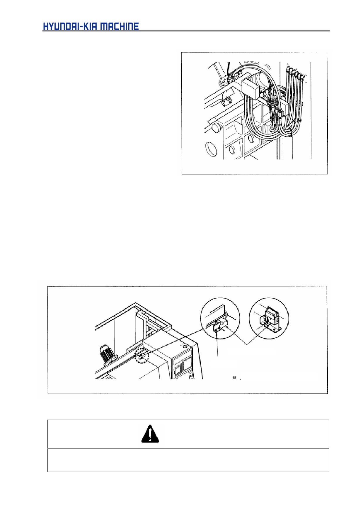
a. Disassemble the cover at the
rear of machine and check
hoses for damage in the Z-axis
direction and two hoses in the
X-axis direction.
b. Attach the cover.
Fig. 5-30 Checking Moving Hose
4) Cleaning Front Cover of Spindle
For detailed information, see chap. 3-1-2 "Cleaning Front Cover of Spindle".
2-6-2. Around the Machine
1) Checking the operation of Safety device
Check the limit switch and dog installed on the door for operation.
Limit Switch
Dog
Applicable only to the C.E.
Fig. 5-31 Door Interlock
WARNING
Never change the positions of limit switch and dog installed on the door.
Also, using during stopping operation may cause personal severe injury.
5-40
V. REPAIR AND PRESERVATION
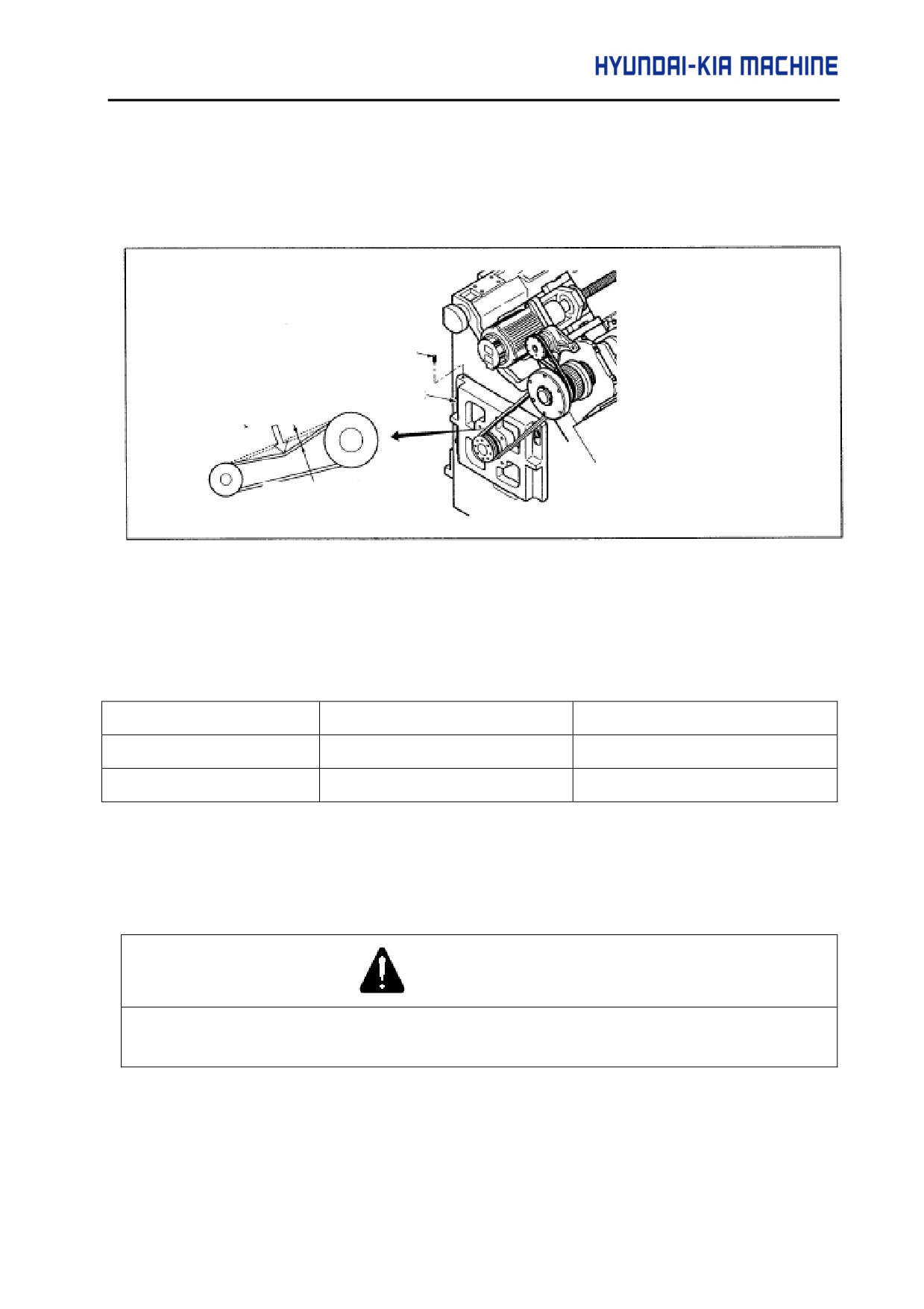
2) Adjustment of Belt Tensions
a. Adjusting the tension of spindle belt.
The spindle belt should
Set Screw
Bracket
F (load)
Displacement
Fig. 5-32 Spindle Belt Tension
Table 5-2. Belt Tension
Unit : mm (in)
Model
Belt Displacement
Load
SKT100
10.8mm(0.43)
15.4kgf(154N)
SKT200
10.9mm(0.43)
17kgf(170N)
Used tool: wrench (6mm and 12mm)
b. Unscrew bolts, turn setscrews under bracket and then adjust the tension.
c. After adjustment of tension, secure bolts and engage the above set screws.
CAUTION
When adjusting the tension belt, tighten both of setscrews in bracket to equally to allot the bracket to
move horizontally.
5-41
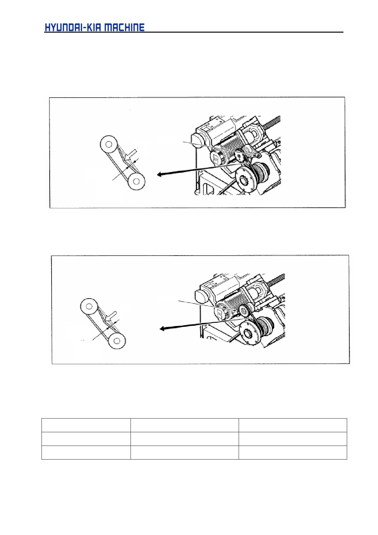
3) Adjustment of position coder timing belt tension
The timing belt should be checked first after one month of installation. Thereafter, check it every
6 months.
Bolt
Load
Displace-
ment
Fig. 5-33 SKT100 Timing Belt Tension
Unscrew a bolt, adjust the tension as in Table 5-3, and engage it again.
Bolt
Load
Displace-
ment
Fig. 5-34 SKT200 Timing Belt Tension
Table 5-2. Belt Tension
unit : mm (in)I
Model
Belt Displacement
Load
SKT100
2.8(0.11)
0.4kgf(4N))
SKT200
3.1mm(0.12)
0.4kgf(4N)
Used tool : Wrench (10mm)
5-42
V. REPAIR AND PRESERVATION
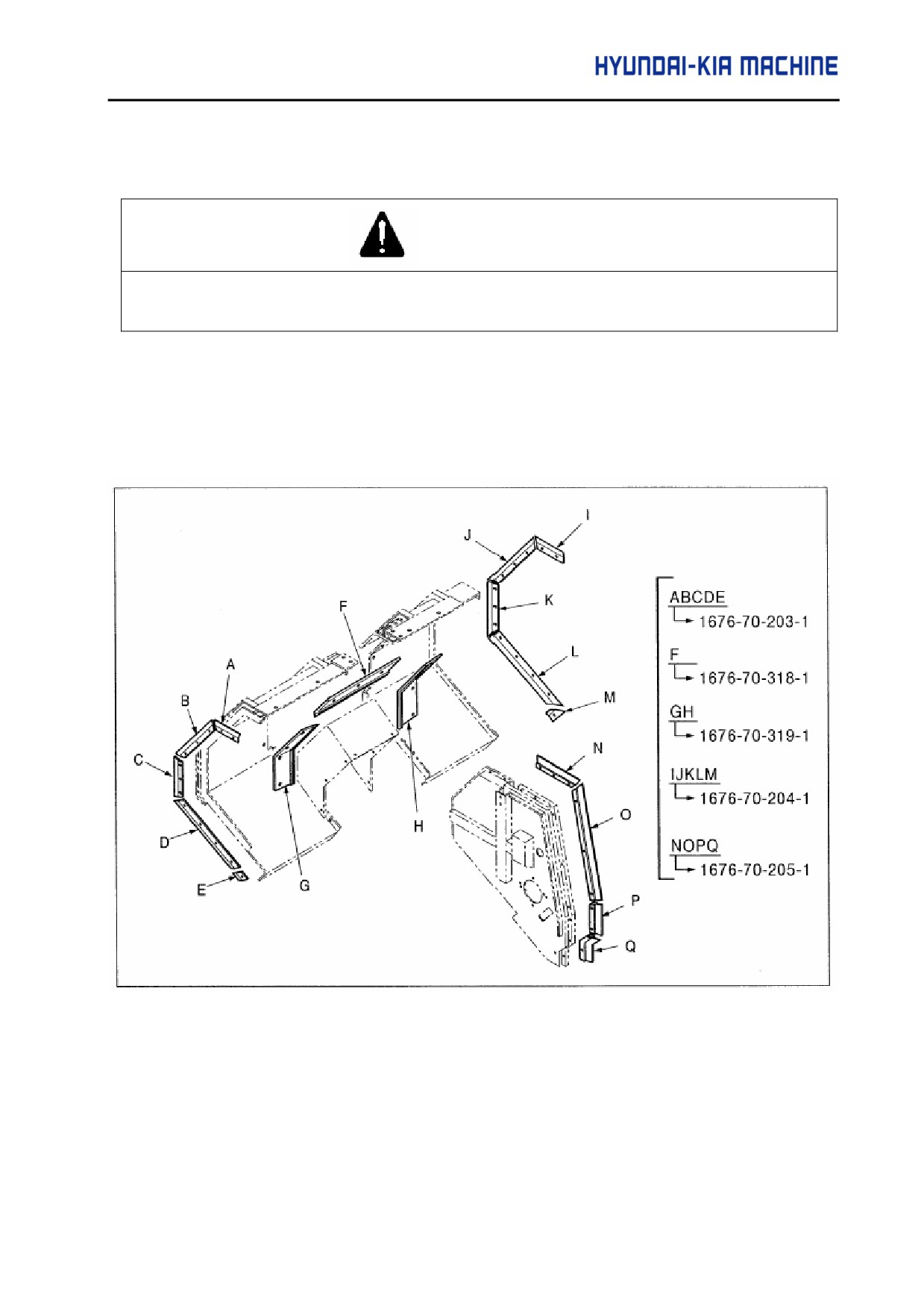
4) Checking and Changing Wiper
DANGER
Always turn OFF the power before repairing the machine. Otherwise, it may cause personal severe
injury.
Check the wipe for operation and if damaged or broken, exchange it with reference to the
following diagram.
Used tool : Wrench (4mm)
Fig. 5-35 Wiper location diagram
5-43
5) Checking and Exchanging X-axis Multicover
DANGER
Always turn OFF the power before repairing the machine. Otherwise, it may cause personal severe
injury.
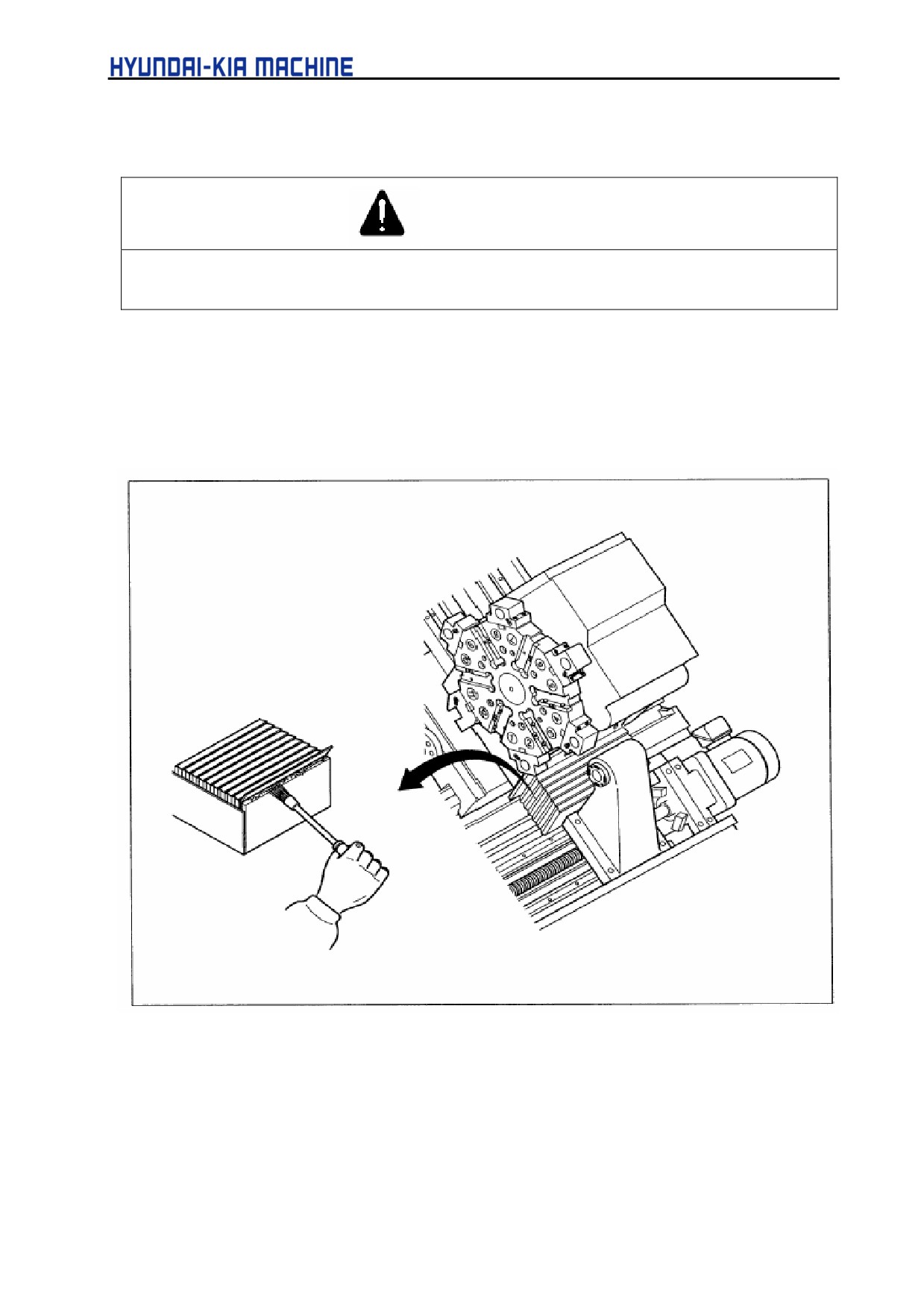
Used tool : wrench(5mm) and brush
a. Check the multicover for operation in the manual feed of X-axis.
b. Raise the stainless plate of multicover, check the inside neoprensheet for damage and then
remove chips.
Fig. 5-36 X-axis Multicover
5-44
V. REPAIR AND PRESERVATION
2-7.
Yearly Check and Repair
2-7-1. Around the machine
1) Work light
Follow the orders as below when cleaning a glass of work light or changing a bulb.
WARNING
When exchanging a bulb, always turn OFF the power. Otherwise, it may cause personal injury.
WARNING
1.
When exchanging a bulb, always wear clean gloves. Otherwise, this can result in contamination
on the bulb and affect on its brightness.
2.
Never grasp a bulb with bare hands.
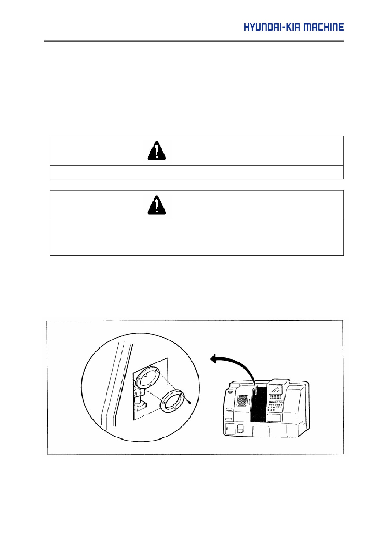
Used tools: wrench (5 mm), damp clothes
a. Unscrew bolts and disassemble the front cover.
b. Remove a bulb by hands and insert new one.
c. Reassemble the front cover.
Fig. 5-37 Changing a Bulb of Work Light
5-45
2) Checking and Repairing Levelling bolt
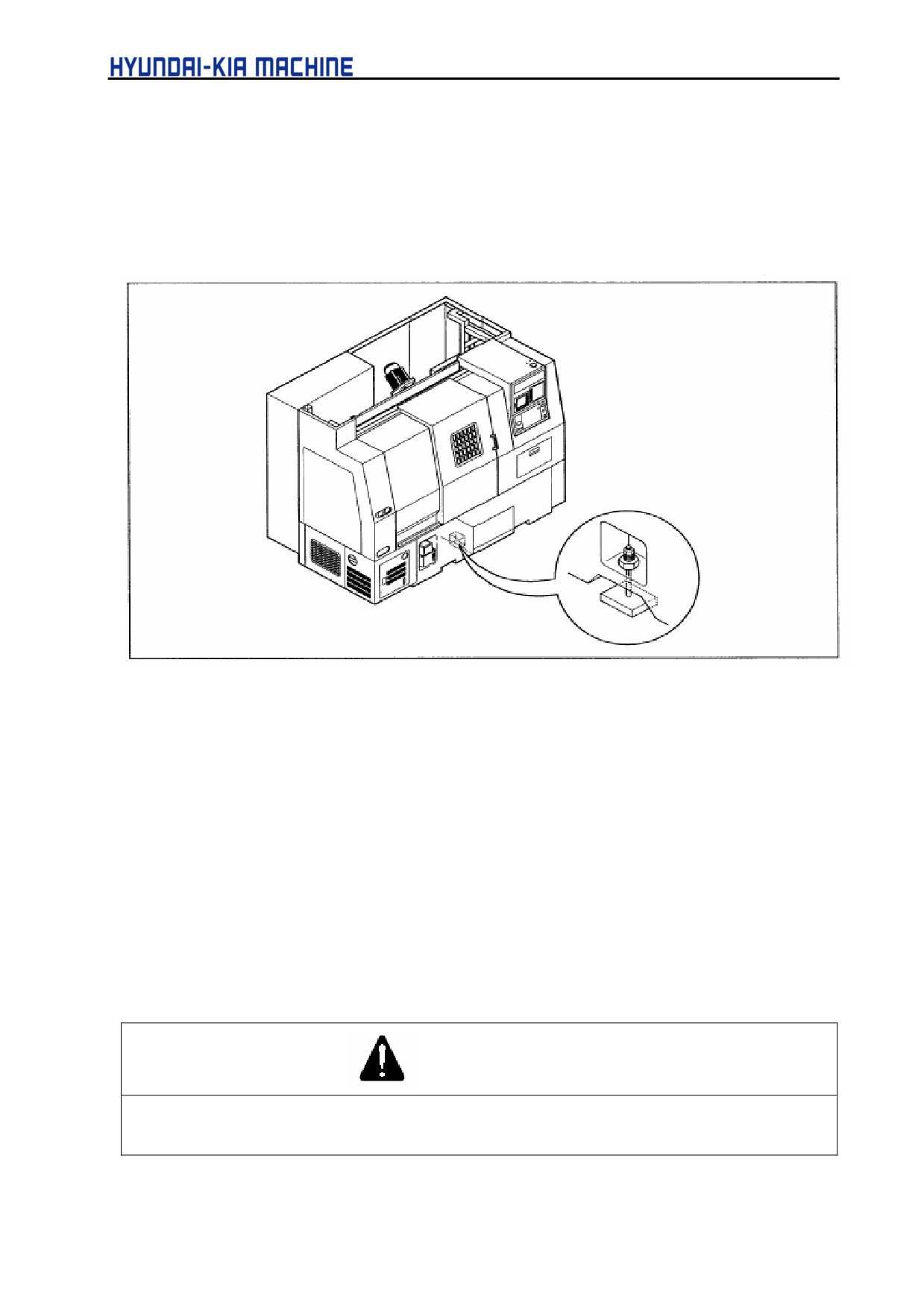
Used tool:
spanner (24 mm)
a. Check the levelling bolt and nut for looseness.
b. For the adjustment of level, see chapter 4 "Transport and Installation".
Fig. 5-38 Checking Levelling Bolt
3) Adjustment of Backlash in Each Axis
See para. 1-4 "Adjustment of backlash in X- and Z-axes".
2-8. Check and Repair Before Long-term Storage
Check and repair if the machine is stopped for more than 2 weeks as follows:
(1) Apply rust-proof oil.
(2) Remove coolant.
(3) Save the NC data.
1) Rust-proof
DANGER
Before applying rust-proof oil, turn OFF the main power of machine. Otherwise, it may cause personal
injury.
5-46
V. REPAIR AND PRESERVATION
During the long-term storage of machine, always apply the following units and parts with
rust-proof oil.
c
Vertical Motion Bearing(X- and Z-axes)
d
Ballscrew (X- and Z-axes)
e
Slider cover (X- and Z-axes)
f
Turret head
f
Work light
2) Collect coolant
Remove coolant in the main and the sub coolant tanks. For detailed information, see the desired
one of para. 2-6-1 "Filling and Changing oil".
3) Save the NC data
Save the NC data in PC.
2-9.
Check and Repair Before Operation Since Long-term Storage
Check and Repair before operation since long-term storage as follows:
(1) Remove rust-proof oil.
(2) Supply coolant.
(3) Perform general checks prior to operation.
(4) Check for oil leakage.
(5) Idling.
(6) Check a noise, vibration and the abnormal higher temperature, etc.
1) Cleaning rust-proof oil
Clean all unit parts free from rust-proof oil applied in para. 2-8 "Check and Repair Before
long-term Storage". Use damp clothes and cleaning solutions.
2) Supplying coolant
For detailed information, see para. 2-6-1 "Filling and changing oil".
3) General Checks
For detailed information, see para. 2-2 "Check and Repair Items"
4) Checking for oil leakage
Check there is an evidence of oil leakage inside of the machine or hoses.
5-47
5) Warm up of Machine
A. Warm up of Spindle
Before operating since stopped for a long time, idle the machine in the following orders.
a. Clamp the rotation speed of
spindle to
1.000 rpm for a
safety.
b. Rotate the spindle with
500
rpm for half an hour.
c. Rotate the spindle with 1.000
rpm for half an hour.
d. Stop the spindle.
WARNING
If rotating the spindle in a high speed suddenly since stopped for a long time, it may result in a failure of
the spindle bearing or chuck cylinder.
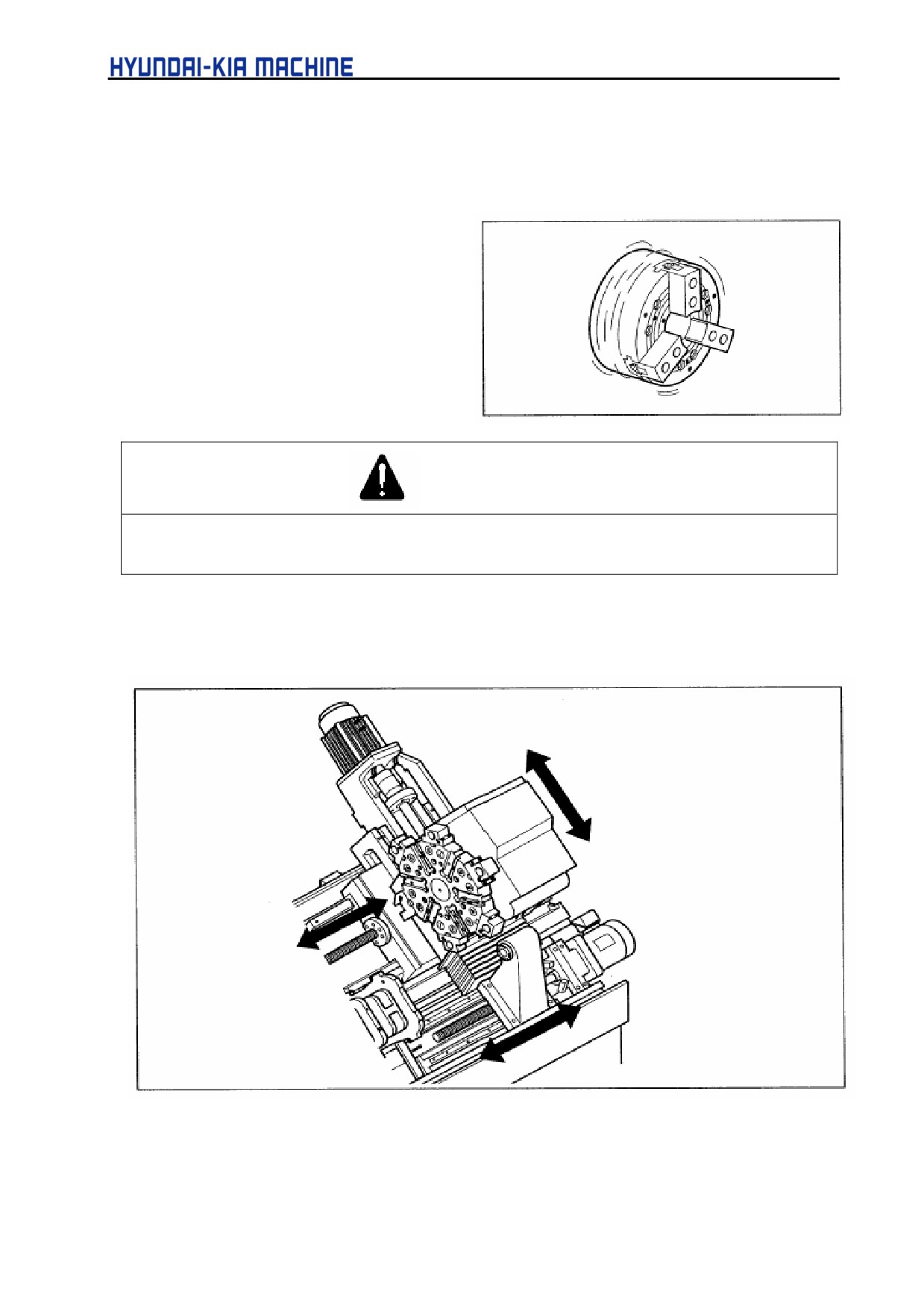
B. Warm up each axis (X- and Z-axes) and Tail Stock
Idle X- and Z-axes for half an hour before operation since stopped for a long time.
Fig. 5-49 Warm up Each Axis and Tail Stock
5-48
V. REPAIR AND PRESERVATION
3.
Maintenance of Major Units
3-1.
Spindle
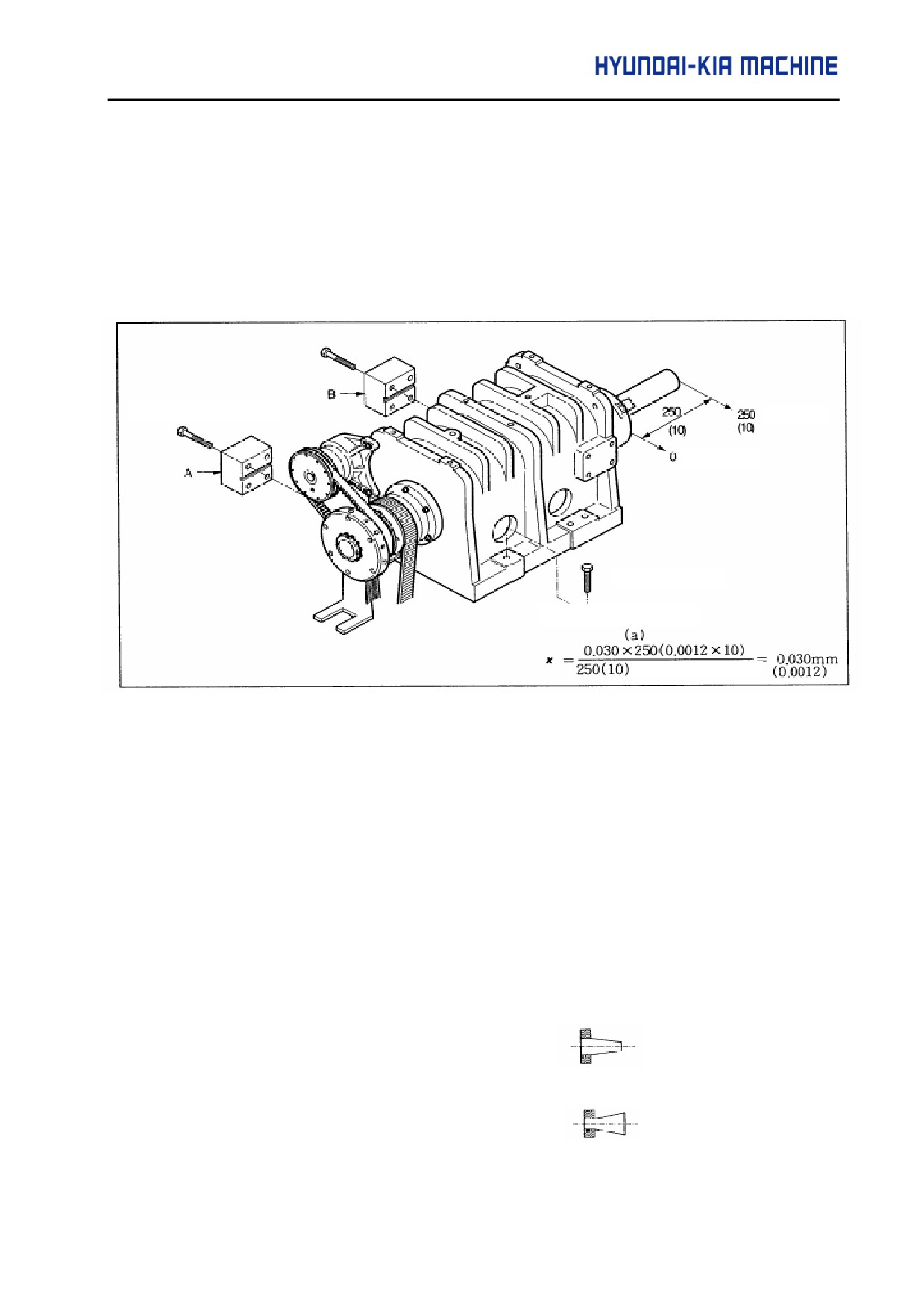
3-1-1. Adjustment of Degree in Spindle
If the spindle changed its position or disassembled for maintenance, adjust as follows:
Pad mounting bolt
Position
Position
Spindle Bolt
Calculation formula
(measured length)
Fig. 5-40 Adjustment of Spindle Accuracy
Used tools: spanner (24 mm), dial gage (0.002 mm)
Material:
∅ 50x250 (∅ 2x10) aluminium or cast-iron
1) Loosen spindle bolt and disassemble into the bolt of A and B pads. Re-assemble A and B pads
and engage spindle bolt.
2) Measure the material for testing (length: 250 mm).
3) Cut the material for testing (fine cut).
4) Measure the roundness of workpiece (For example).
If the difference (overhall length of 250 mm (10)) of cylindricity is 0,015 (0.0006) mm, the
current sum of pad will be 0,030 (0.0012) by the above calculation formula:
c
If the configuration of manufacturing material is
,
polish the grinded surf ace (attached to head stock) of A pad as 0.030 (0.0012).
d If the configuration of manufacturing material is
,
polish the grinded surf ace (attached to head stock) of B pad as 0,030 (0.0012).
5-49
5) Engage bolts for engaging head stock.
6) Fine cut the material for testing.
Adjust the difference of roundness to be less than 0,015 (0.0006) mm.
7) Repeat between 2) and 6) until the roundness reaches to the desired value.
3-1-2. Cleaning Front Cover of Spindle
DANGER
Turn OFF the power when entering the machine for cleaning the front cover of spindle. Otherwise, it
may cause personal injury.
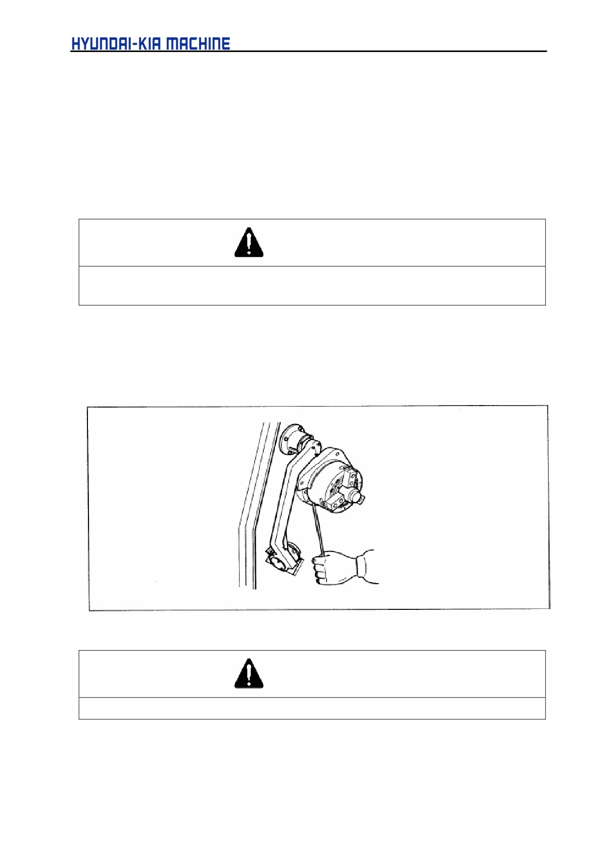
Clean the drain hole located under the front cover of spindle to prevent from being clogged. Drill the
drain hole, using a wire.
Used tool: ∅ 3 wire
Fig. 5-41 Cleaning Front Cover of Spindle
CAUTION
Never use compressed air. It may cause machine failure.
5-50
V. REPAIR AND PRESERVATION
3-2.
X- and Z-axes
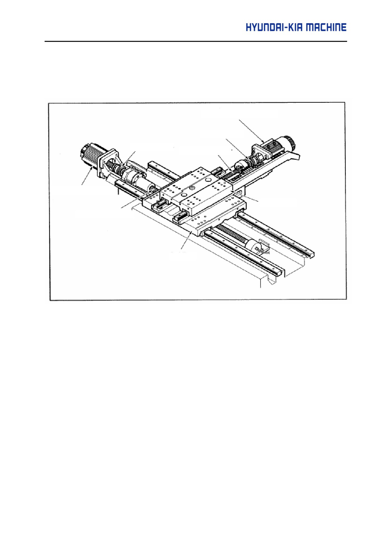
3-2-1. X-and Z-axes Constructions
X-axis Servo Motor
Torque Limiter
Torque Limiter
X-axis Ball Screw
Z-axis Servo Motor
Cross Slide
Z-axis Ball Screw
Saddle
Fig. 5-42 X- and Z-axes Constructions
1) X- and Z-axes are driven by ball screws and AC servo motor.
2) The positions of X- and Z-axes are verified by the encoder installed in AC servo motor.
3) X- and Z-axes servo control units are located in the Electrical Box.
5-51
3-3.
Tool Post
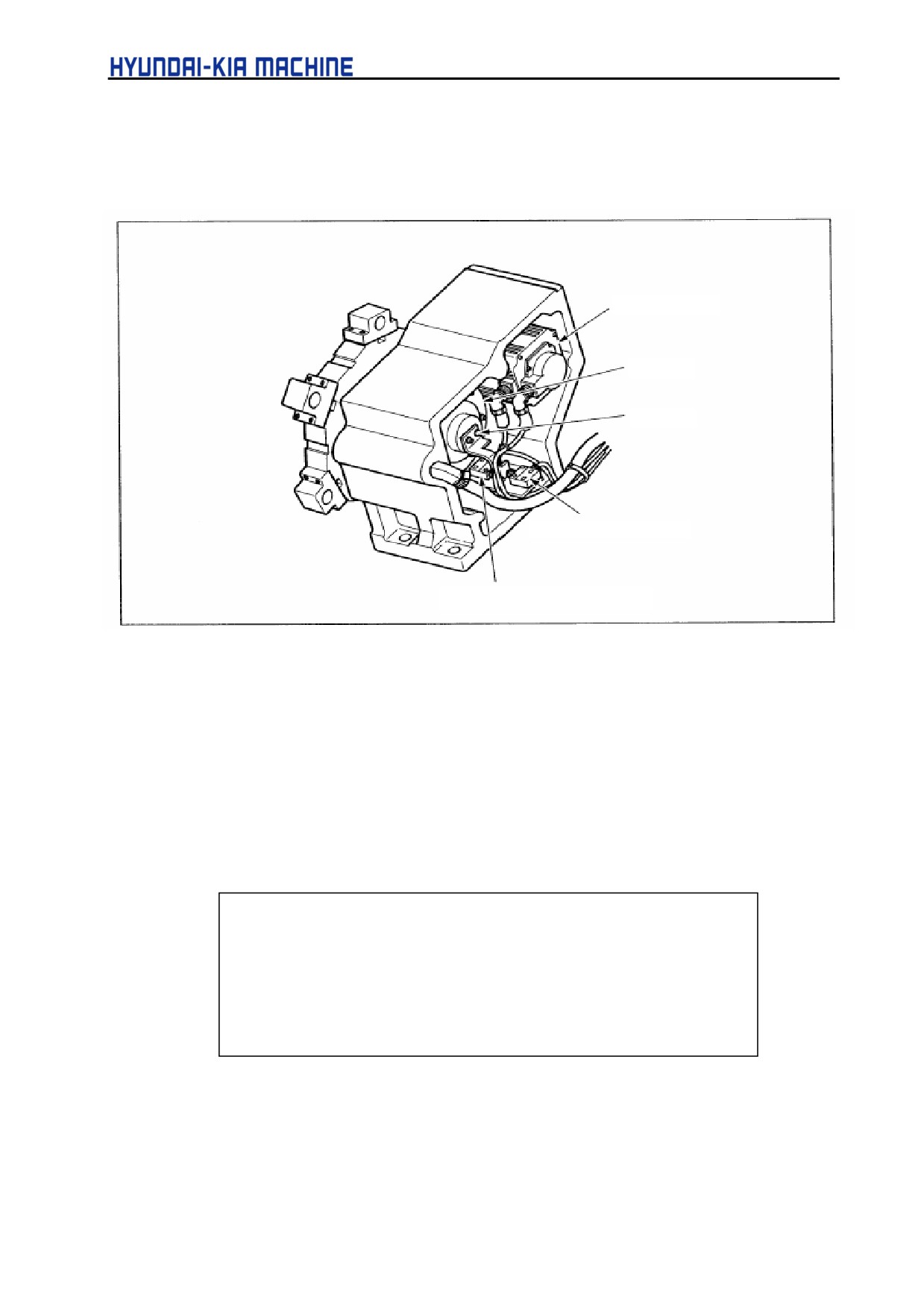
3-3-1. Tool Post Construction
Servo motor
Cylinder
Dog
Clamp Limit Switch
Unclamp Limit Switch
Fig. 5-43 Tool Post Construction
3-3-2. Tool Post Home Position Setting
1) Period of Home Position Setting
Because the absolute position detector is used as the position detection system of tool post
servo, the home position setting of Tool Post should be performed in the following cases. If
indexing the tool post without home position setting, alarm no. “A90” will be displayed on the
servo amp.
c
If have disassembled or reassembled the servo motor
d
If exchanging the servo amp
e
If exchanging the battery
f
If disconnecting the detector connector of servo motor
g
If the absolute position data has been missed by other causes.
5-52
V. REPAIR AND PRESERVATION
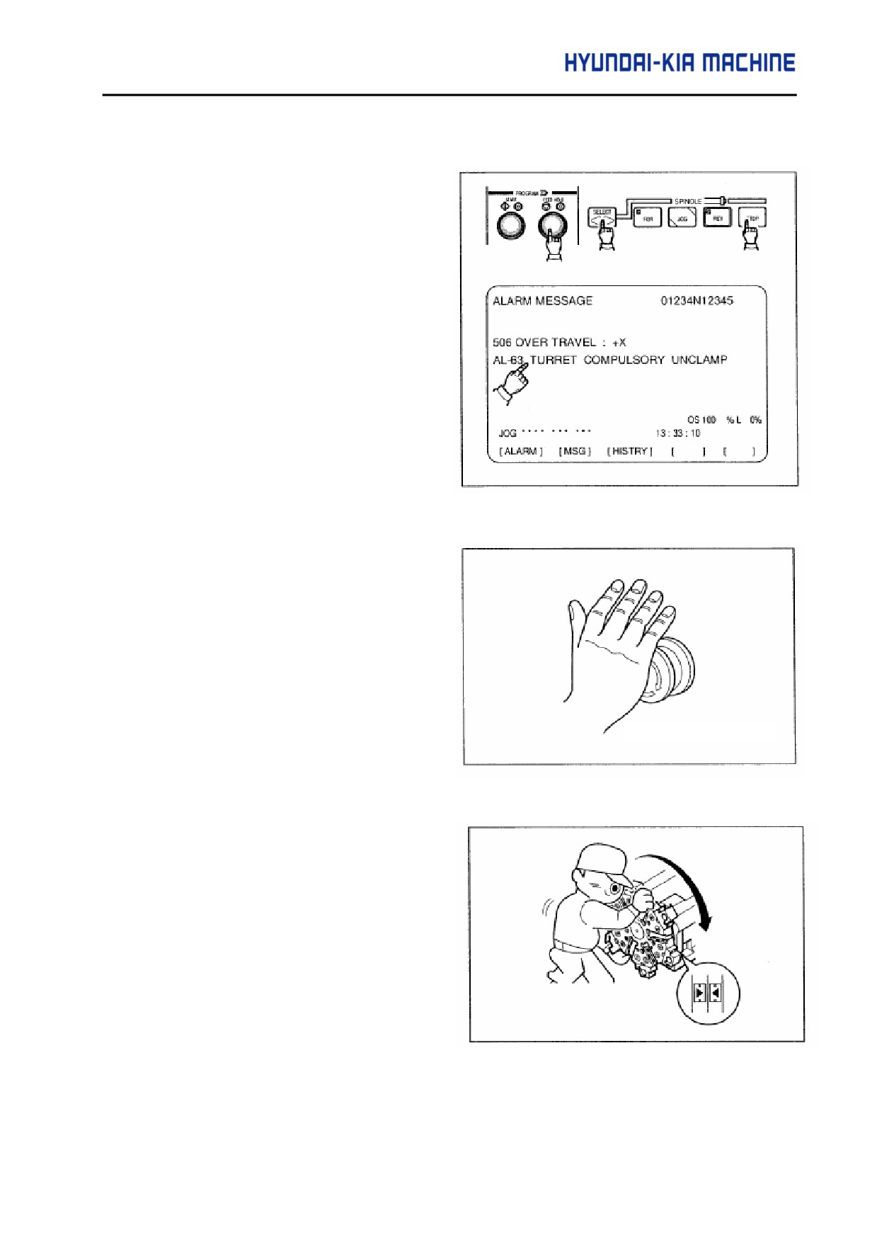
2) Home Position Setting Method
a. Unclamp
the
turret
by
simultaneously
pressing
“[SPINDLE
STOP]”
and
“[SELECT]”, “[FEED HOLD]” on
the Operating Panel.
The Message,
“2067 TURRET
COMPULSORY UNCLAMP” will
be displayed on the alarm screen.
Parameter K0#3="1"
Unclamp
the
turret
by
Simultaneously
pressing
[TURRET INDEX],
[ROTATING
TOOL STOP] on the operating
panel.
b. Press the Emergency Stop switch.
Emergency Stop
c. Turn the turret by hand and set the
No.
1 tool. Turn the turret and
remain it on the position where the
arrows of turret and tool post body
are aligned.
d. Release the Emergency Stop state
and press the "STAND-BY" switch.
5-53
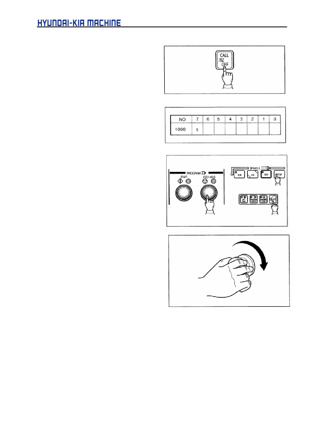
e. Press the “CALL LIGHT OFF” switch.
The turret is clamped and ALARM
“2067” disappears on the alarm
screen.
f.
Verify that bit "7" of X1000 has been
changed to "1" in the diagnostic
screen.
g. With the Emergency stop switch
pressed, press the Spindle
“STOP”
Mode "SELECT”, and “FEED HOLD”
switches simultaneously.
h. Reset the Emergency Stop switch.
Now the home position setting of tool
post is completed and enables the
turret index.
5-54
V. REPAIR AND PRESERVATION
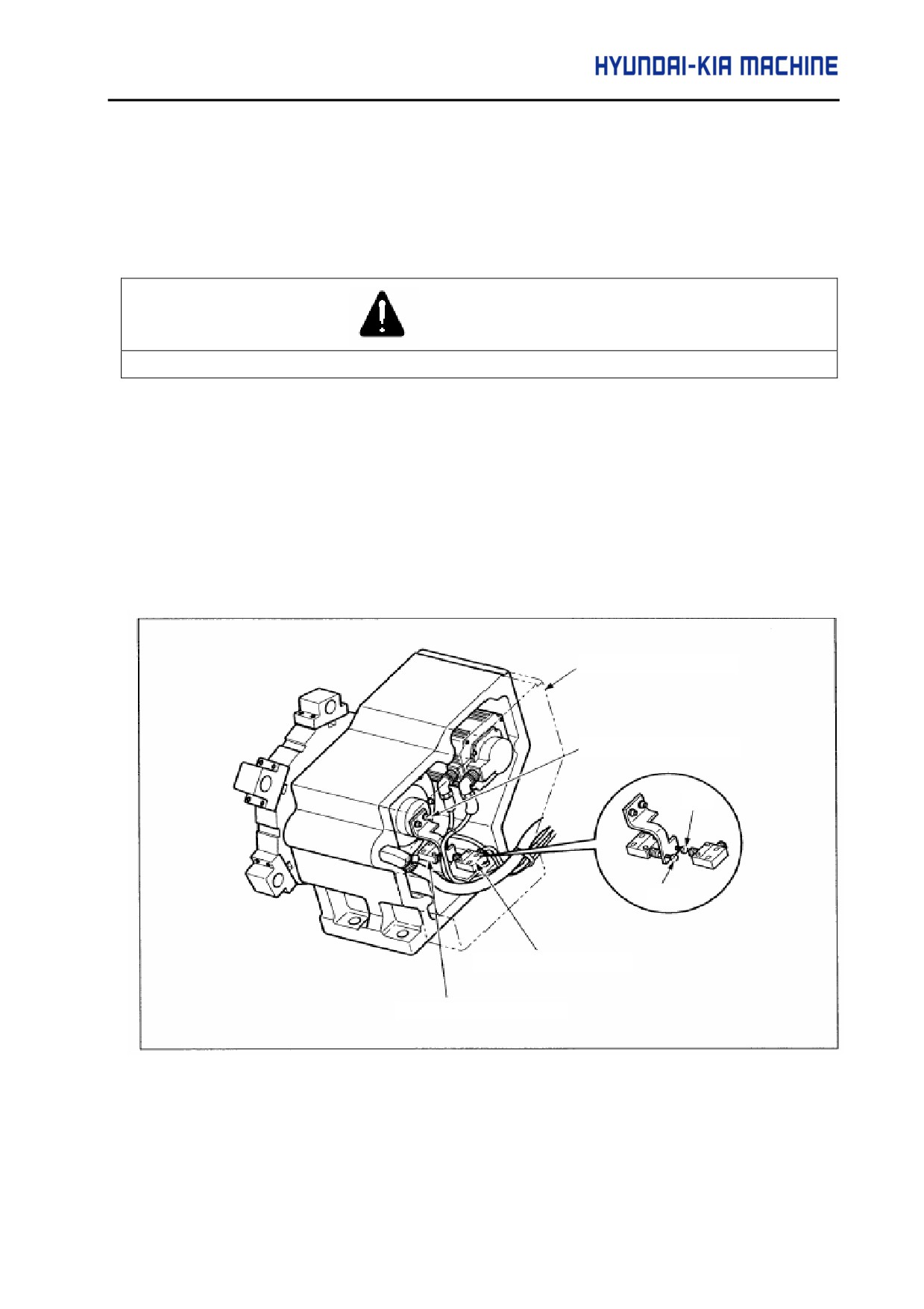
3-3-3. Adjustment and Exchange of Clamp, Unclamp and Limit Switches.
If clamp and unclamp operations are not satisfied or the limit switch requires to be exchanged,
adjust as follows:
WARNING
Prior to implementing the actions, turn OFF the power. Otherwise, it may cause personal severe injury.
Used tools: wrench (5 mm), spanner
1) Disassemble the cover.
2) Adjust the dog bolt.
3) If exchanging the limit switch, disassemble engaging bolts, replace and then engage the limit
switch (Adjust the dog bolt).
4) Attach the cover.
Cover
Dog
Bolt
Bolt
Clamp Limit Switch
Unclamp Limit Switch
Fig. 5-44 Adjustment and Change of Proximity Switch
5-55
3-3-4. Restoration in Collision of Turret
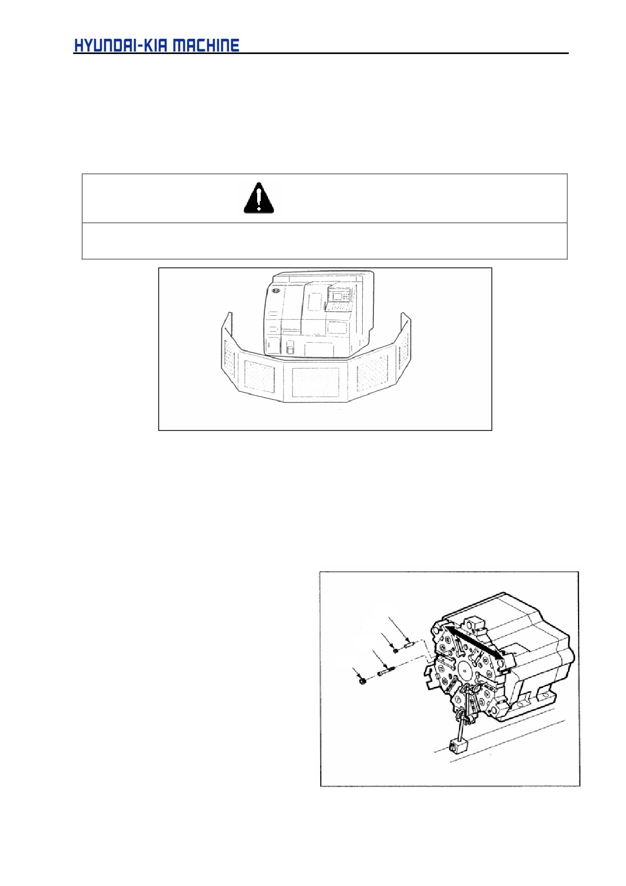
If the turret is collided by crash, misoperation or program error while turning, correct it in the
following orders.
WARNING
If the power required, always install the safety guard and then work inside of the machine. Otherwise, it
may cause personal severe injury.
Under Repairing
Fig. 5-45 Installation of Safety Guard in Repairing.
Used tools: dial gage (0,002 mm)
∅ 9.8 drill
wrench (8 and 10 mm)
∅ 10 reamer
1) Perform the Home Position Setting of
turret as shown in param.
3-3-2
"Turret Home Position Setting".
Pin
Plug
2) Install the dial gage on the surface
No. 1 of turret and check the X-axis
Bolt
Plug
for flat.
3)If the flatness of turret is more than 0.02
mm, disassemble the plug and pin in
front of turret and loosen the bolt
properly.
4) Adjust the turret so far the flatness is
within 0.02 mm and engage the bolt.
Fig. 5-46 Repairing Turret
5-56
V. REPAIR AND PRESERVATION
5) After engaged, check again for the flatness.
6) Engage the pin to be deviated as 90° from the position of pulled out.
7) Close the plug after pin works.
8) Check for the flatness.
If the turret has been collided
during rotation
Motor
Spare Gear
Verify 1) and 2) and if the flatness is
within the desired value, follow the
Bolt
instructions given below.
Retainer
a. Loosen the bolt and remove a
bundle of motor.
b. Disassemble
the
gear
engaged with motor shaft and
reengage it not to be slided.
Fig.5-47 Repairing Turret
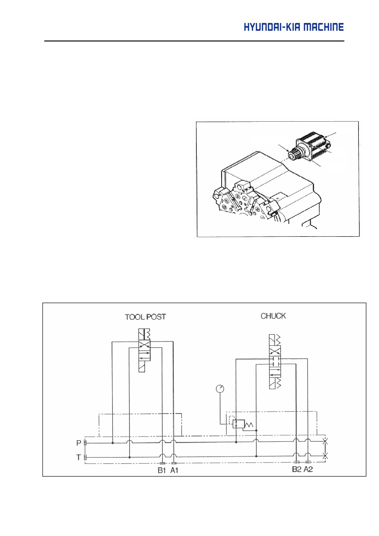
3-4. Hydraulic
3-4-1. Hydraulic Circuit Diagram
Fig.5-48
Hydraulic Circuit Diagram
5-57
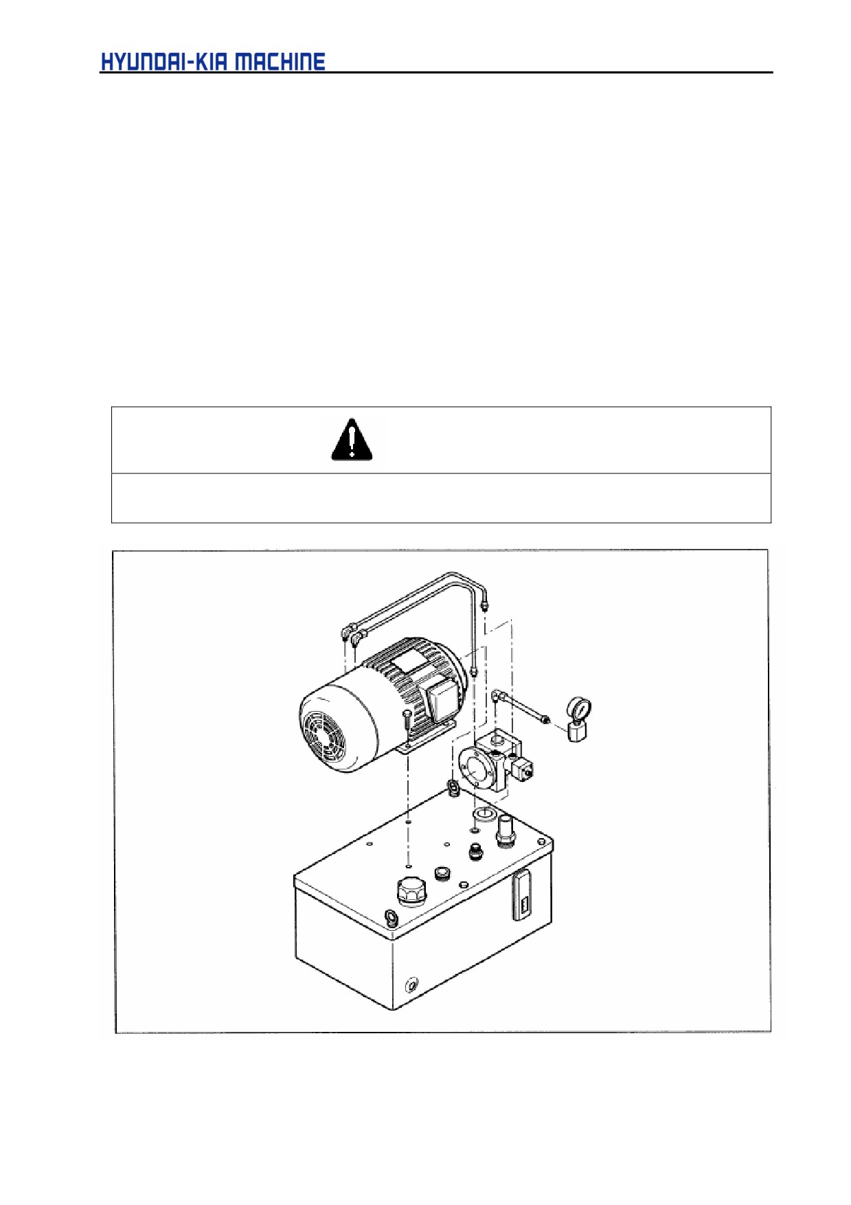
3-4-2. Repairing Hydraulic Tank
If there is an abnormal noise or high temperature in the hydraulic tank, check, repair and replace the
pump and motor, if necessary.
1) Turn OFF the power
2) Disassemble the bolt installed in the pump.
3) Disassemble the bolt connected the motor with pump.
4) Disconnect the pump from motor.
5) Apply the power and check the motor for rotation sound.
6) If the rotation sound of motor is high, change the motor.
7) If the motor is normal, change the pump.
CAUTION
Before applying the power since the pump has been changed, fill the filler hole installed on the pump
with hydraulic oil. Otherwise, it may cause the pump burnout.
Fig. 5-49
Hydraulic Tank Disassembly Diagram
5-58
V. REPAIR AND PRESERVATION
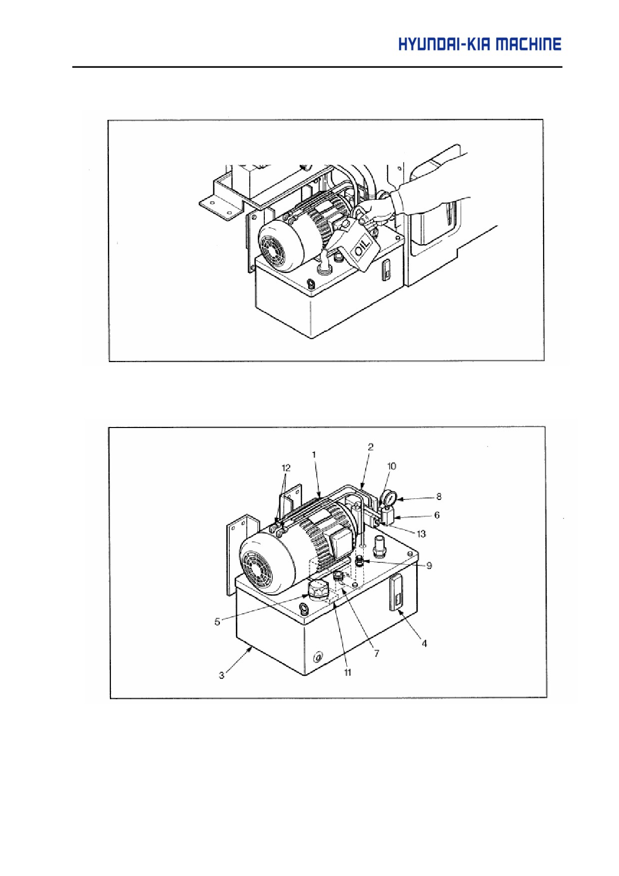
Fig. 5-50 Oiling After Changing Pump
Fig.5-51
Hydraulic Tank
5-59
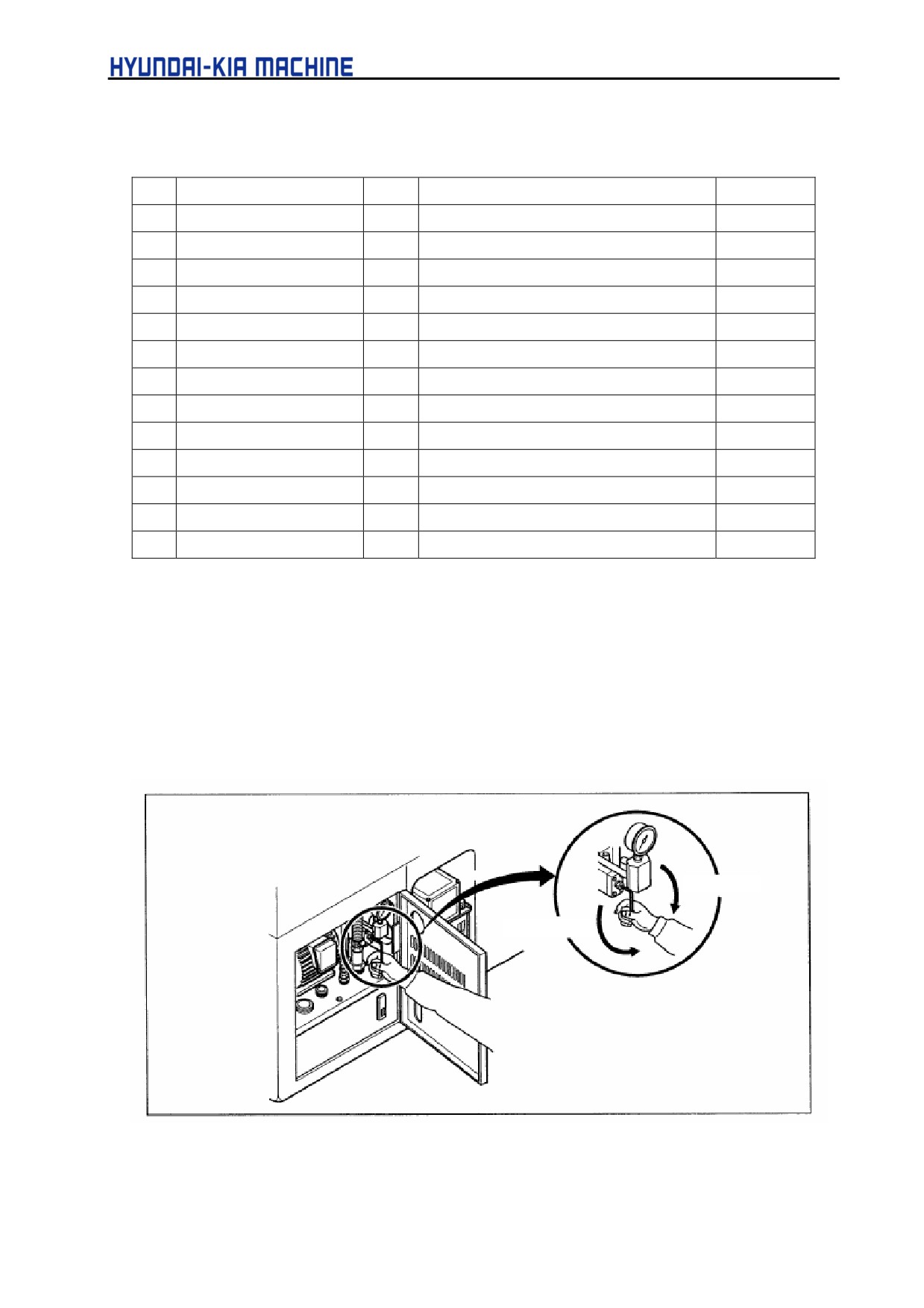
Table 5-4. Hydraulic Tank Parts List
No.
Nomenclature
Qty.
Type
Remark
1
Motor
1
0,4Kw x 4P
2
Vane pump
1
MFG.S-2993
3
Oil Tank
1
10 liter
4
Oil Level Gage
1
VA-01
5
Air Bleed
1
6
T-chuck valve
1
CT-T03-0-4044A
7
Strainer
1
8
Pressure Gage
1
PT1/4 Ø 60 x 70 kgf/cm2
9
Socket
3
PT3/8
10
Nipple
1
PT3/8XPF1/4
11
Separator
1
40x25x10 mm
12
Nipple
2
13
Nut
1
M8
3-4-3. Pressure And Flow Adjustment
The pressure and flow of hydraulic unit have been adjusted at factory and need not to be done
specially. However, for the hydraulic chuck or tail stock it requires to be adjusted. If adjusting it, follow
the instructions given below.
1) Adjustment of Main Pressure
Increment
Decrement
Fig. 5-52
Adjustment of Main Pressure
5-60
V. REPAIR AND PRESERVATION
Used tools:
wrench (5 mm) and spanner (17 mm)
a. Loosen the nut using spanner.
b. If turning clockwise, the pressure is increased and if anticlockwise, it is decreased.
c. After adjusting, engage the nut using spanner.
WARNING
The main pressure is specified to 35 kgf/cm2. If used over the specified value, it may cause machine
failure.
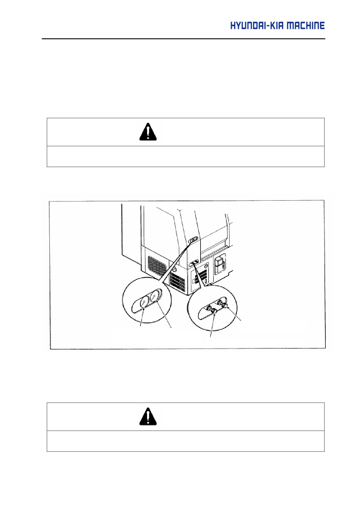
2) Adjusting the pressure of chuck and tail stock
Chuck Pressure Control
Valve
Chuck Pressure
Tail Stock
Gage
Pressure Gage
Tail Stock Pressure Control Valve
Fig. 5-53 Adjustment of Chuck and Tail Stock Pressure
If turning the pressure regulating valve knob clockwise, the pressure is increased and if anticlockwise, it
is decreased.
WARNING
The pressures of chuck and tail stock are specified to 27 kgf/cm2 and 20 kgf/cm2. If used over the
specified value, it may cause machine failure.
5-61
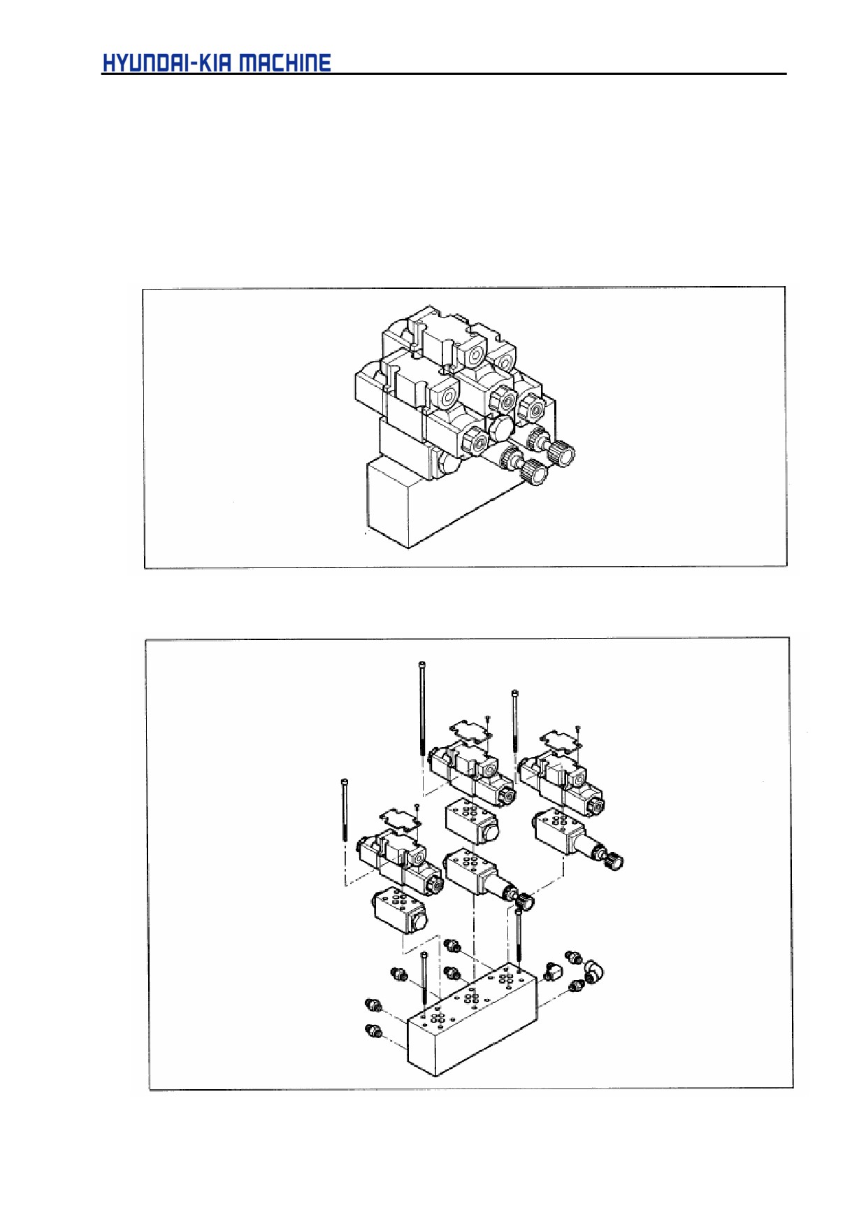
3-4-4. Repairing Manifold
A high level unit composed level the solenoid valve (direction converting valve),
hydraulic control valve, check valve, and etc..
1) Manifold construction
Fig. 5-54 Manifold Construction Diagram
Fig. 5-55 Manifold Disassembly Diagram
5-62
V. REPAIR AND PRESERVATION
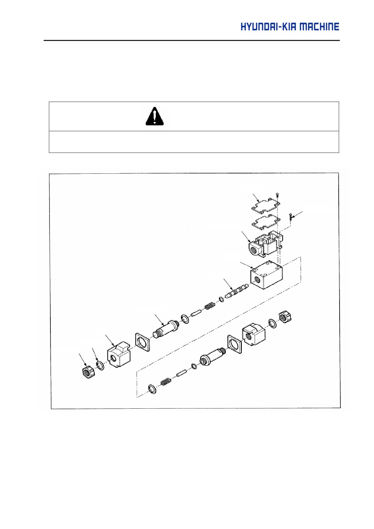
2) Exchanging solenoid valve
In case of failures due to the broken internal spool or poor spring, disassemble, clean or
change the damaged solenoid valve in the following orders.
CAUTION
After stopping operation, the solenoid will be hot and cause burns in disassembled and exchanged.
Turn off the power, cool sufficiently and then replace it.
Plate
Screw
Terminal Box
Body
Spool
Cartridge
Coil
O-ring
Resin Nut
Fig. 5-56
Solenoid Valve Disassembly Diagram
Used tools:
+ screwdriver, wrench (4 mm)
5-63
A. Exchanging solenoid coil
a. Loosen and disassemble resin nut from solenoid coil.
b. Disassemble the washer and O-ring.
c. Pull out the coil in the axis direction and disassemble it from the body. Reassemble it in
the reverse order.
CAUTION
Torque the resin nut to 40-50 kgf • cm (4 ~ 5 N • m).
B. Disassembling and cleaning the solenoid valve
If the solenoid valve clogged with foreign matters, disassemble and clean the body as follows:
a. Turn off the power.
b. Disconnect the coil.
c. Remove four bolts from the terminal box.
d. Disconnect the base plate.
e. Loosen and disconnect cartridge.
f.
Disconnect internal parts from the body.
g. Pull out the spool from body without forced power.
h. Clean body and each parts.
i.
Check each parts such as O-ring and then reassemble them.
CAUTION
1.
When assembling the spool in the body of solenoid valve, never push it with a force.
2.
Make sure there are no foreign matters in the valve.
3.
Torque the cartridge to 390-420 kgf • cm (39 ~ 42 N • m).
j.
Attach the base plate.
CAUTION
Torque the plate to 5.5 ~ 8.2 kgf • cm (0,55 - 0,82 N • m).
5-64
V. REPAIR AND PRESERVATION
k. Install the terminal box
l.
Install the solenoid coil
m. Connect wires and turn ON the power
n. Check the hydraulic units for operation.
C. Exchanging the solenoid valve
CAUTION
Solenoid valve is in the high temperature, therefore be careful not to be burned.
a. Turn OFF the power.
b. Remove four screws attached with the terminal box.
c. Disconnect wires.
d. Loosen the bolt securing valve.
CAUTION
When disconnecting bolts, make sure the reduction valve, check valve, and etc. are not
disconnected.
e. Install new solenoid valve.
f.
Torque the bolt to 40 - 50 kgf • cm(4 ~ 5 N • m).
CAUTION
1.
Make sure O-ring between each blocks is not disconnected.
2.
Avoid overtorque. It may cause a failure.
g. Connect the wire of terminal box.
h. Apply the power.
i.
Check for oil leakage.
j.
Check the hydraulic units for operation.
5-65
3-5. Lubrication Device
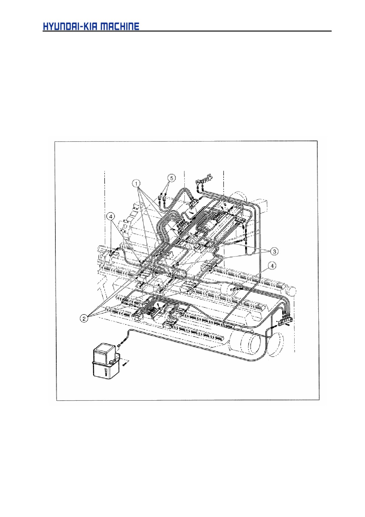
3-5-1. Place to be Lubricated
1)
4 places of bearing in the linear movement of X-axis.
2)
4 places of bearing in the linear movement of Z-axis.
3)
1 place of X-axis ballscrew and 2 places of support bearing.
4)
1 place of Z-axis ballscrew and 2 places of support bearing.
5)
2 places of tool post.
Fig. 5-57 Place to be Lubricated
5-66
V. REPAIR AND PRESERVATION
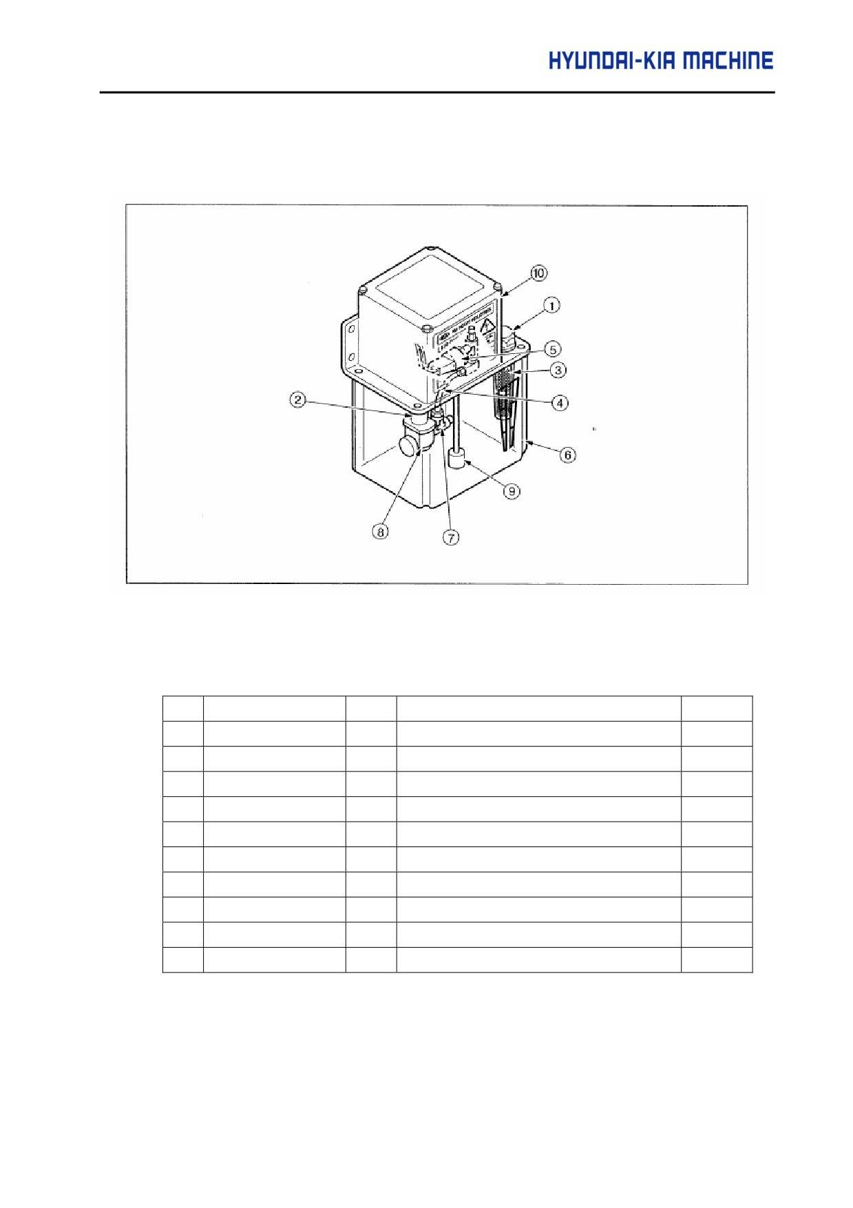
3-5-2. Cleaning Lubrication Unit
1) Construction
Fig. 5-58 Lubrication Unit construction
Table 5-5. Lubrication Unit Parts List
No.
Nomenclature
Qty
Model
Remark
1
Oil cap
1
2
Shaft guide
1
3
Filter
1
4
Hose
1
Ø 6(Ø 0.024)
mm(in)
5
Pressure switch
1
6
Oil tank
1
1800cc(0.47 gal)
7
Relief valve
1
8
Gear pump
1
See next page.
9
Float switch
1
10
Motor
1
15W(0.02HP) 2P
5-67
2) Using Lubrication Oil Pump and Motor
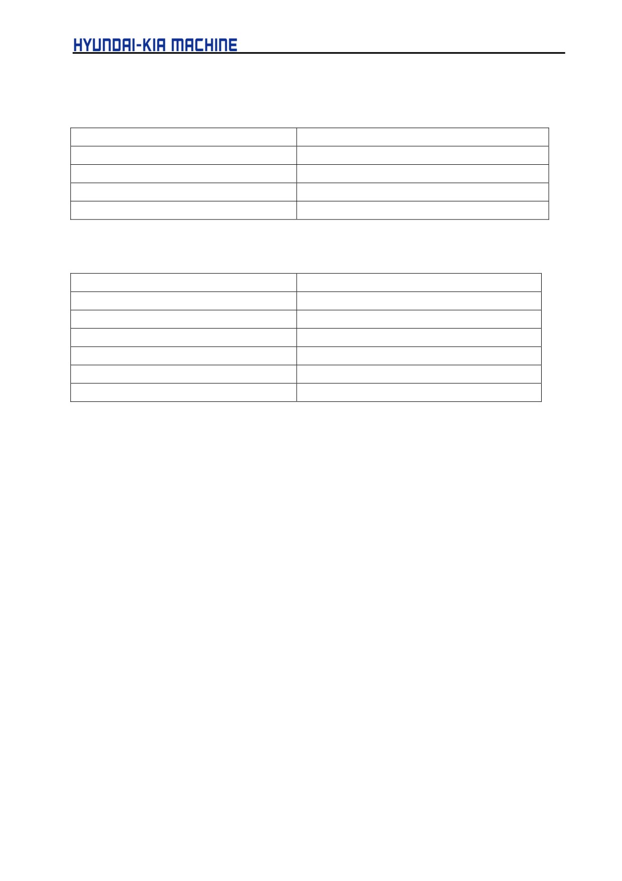
A. Pump
Item
Specification
Discharge
100cc/min (0.02 gal/min)
50/60Hz
Maximum Discharge pressure
8 kgf/cm2(0.8MPa)
Voltage
AC 110V(10)
Frequency
50/60Hz
B. Motor
Item
Specification
Power
15W (0.02HP)
Polarity
2P
Voltage
110V
Frequency
50/60Hz
Rated current
1.0/1.2 A
Revolution number
3000/3600 rpm
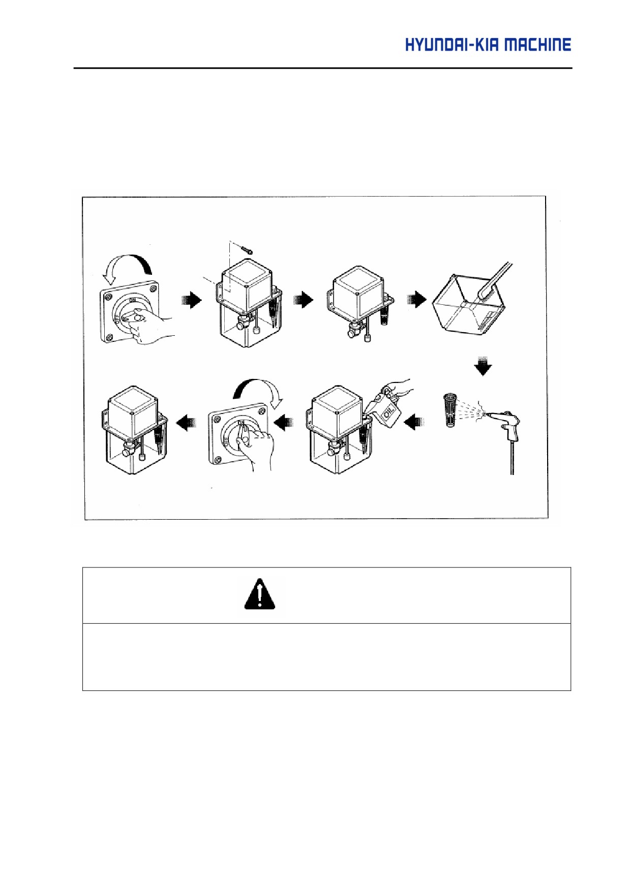
C. Cleaning Lubrication Unit
Used tools
:
wrench(5mm), + driver
a. Turn OFF the power.
b. Loosen bolts and disconnect the unit.
c. Disconnect the tank using + driver.
d. Clean the inside of tank.
e. Remove the filter from the suction port.
f.
Clean the filter using kerosene.
g. Remove foreign matters from the filter using compressed air.
h. Mount the filter.
i.
Mount the tank.
5-68
V. REPAIR AND PRESERVATION
j.
Install the unit.
k. Supply lubricating oil.
1.
Turn ON the power.
m. Check the wet moving part are being supplied with lubricating oil.
Fig. 5-59 Cleaning Lubrication Pump
WARNING
When cleaning the pump, remove oil dropped on the floor. Otherwise, it may cause personal injury.
5-69