Hyundai SKT 100/200 CNC TURNING CENTER. INSTALLATION MAINTENANCE MANUAL (VERSION No.: VOL1.0) - page 3
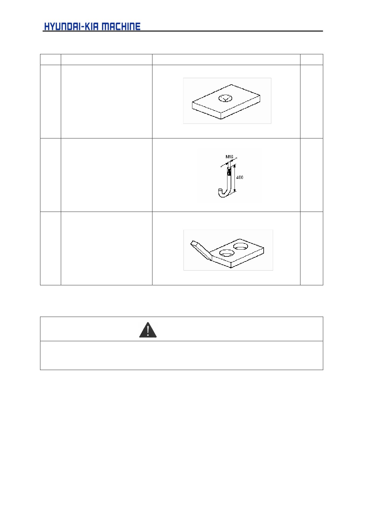
No.
Name and Number
Figure
Qty.
1676014040
3
(Leveling Seat)
6
4
Foundation Bolt
6
1676-09-301-0
5
(Level-Plate)
1
4-2. Foundation Work
CAUTION
Special attention should be paid o the foundation work since it have great influence on maintaining the
accuracy of working and initial installing for a long time.
a. To install the machine, it needs the concrete floor over 300mm in thickness. Put the! levelling
set under the levelling bolt.
b. To maintain machine accuracy, install new concreat ground at the place where has 1 less
than 300m in thickness (See Para. 4-5, Foundation Work).
4-8
IV. TRANSPORT & INSTALLATION
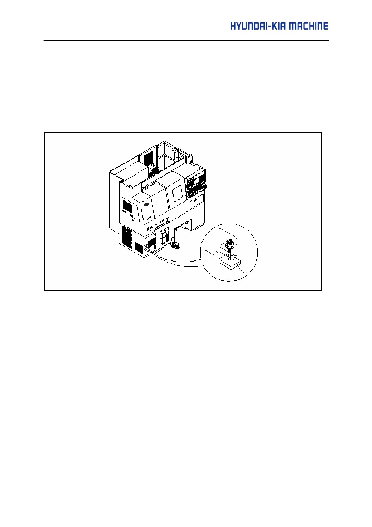
4-2-1.
Without using Foundation Bolt
a. Put the levelling seat at the place shown in foundation diagram.
b. After inserting the levelling bolt in the machine, put it above the levelling seat with about
10mm distance from the upper side of levelling seat.
c. Adjust the levelling bolt, set the level of machine correctly and then tighten the levelling
nut.
Fig. 4-4 Installation of Levelling Bolt
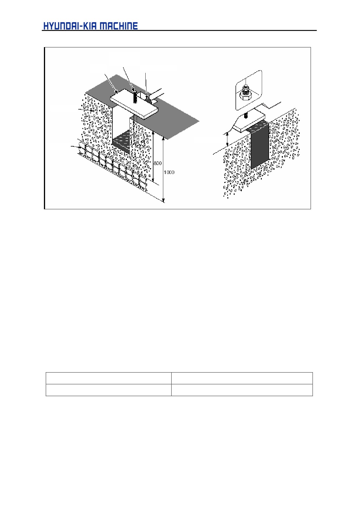
4-2-2.
Using Foundation Bolt (Optional)
a. Place the machine at the place to be installed and perform the 1st levelling work. If the
levelling seat is out its position or it is impossible to adjust it with the levelling bolt due to
poor foundation, use a wedge to do a levelling work.
b. After a completion on the first levelling work, insert the foundation bolt from the bottom of
machine and install it to the machine using nuts.
c. Fill the mortar up to the bottom and the side of levelling sear and stir it with a bar.
d. Adjust the levelling bolt, complete levelling work in all sides, and then engage the
foundation bolt tightly.
4-9
Foundation
Bolt
Seat
Mortar
Concrete
10 - 15 mm
Gravel
Fig. 4-5 Foundation Work
5.
Adjustment of Level
(1) The levelling method is one of the factors to determine the degree of machine.
(2) Levelling the machine is the most- basic work and has an influence on the degree of the
workpiece and the life of machine itself.
(3) Perform levelling in the following order.
a. Install the machine on the floor to be installed as shown in the chapter 4, "installation"
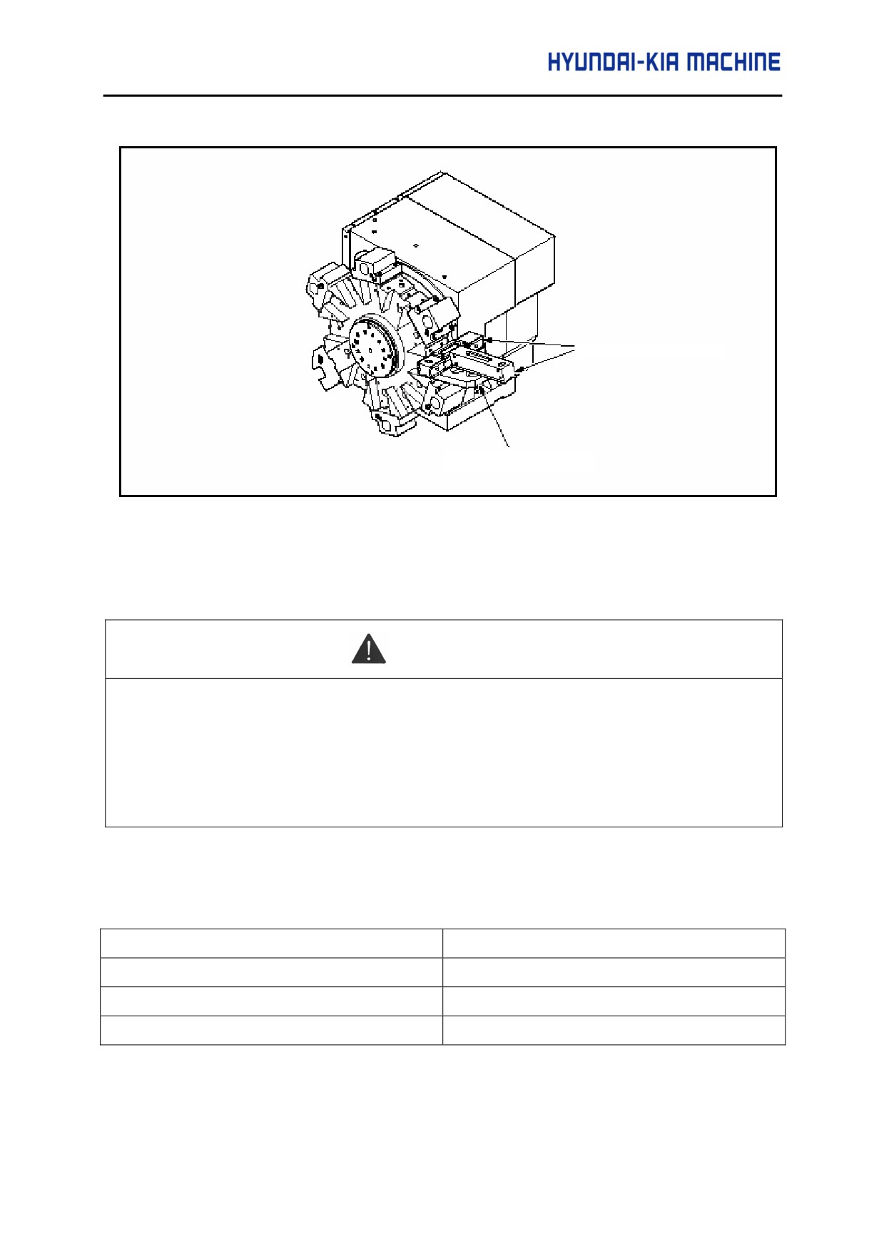
b. Attach the level plate to the turret as shown in Fig. 4-6.
c. Place the level above the level plate.
d. Move the level much as the full feed in 2-axis (430mm 16.93in) and then read the result.
At the time, adjust the level using the levelling bolt so that the difference from the
reading is ±0.04mm/m (±0.00157in/40in)
Level Tolerance
0.04 mm/m(0.00157in/40in)
Level Accuracy
1 scale = 0.02 mm/m(0.00079in/40in)
4-10
IV. TRANSPORT & INSTALLATION
Level
Level Plate
Fig. 4-6 Adjustment of Level
e. Handle the used level enable to maintain the same level in the same direction.
CAUTION
1.
Keep the contact face of level clean to prevent dust, etc. from penetrating the level in
measuring.
2.
Uncontrolled level of the machine may result in malfunction due to declination or worn at
the wet moving part of bed.
3.
When move the level, be careful not to be interfered with chuck and tail stock.
(4) In the last horizontal levelling, do a job with the foundation bolt and nut tightened firmly.
(5) After installing the machine, perform the levelling as follows.
Term
Period
for 2 - 3 days after installing the machine
Daily
for 6 months
Monthly
after 6 months
Quarterly
4-11
6.
Cleaning
(1)
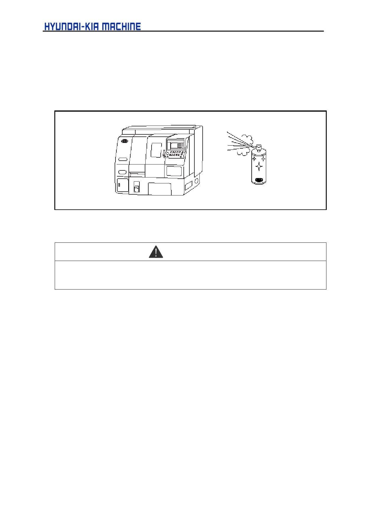
When transporting the machine, there is a risk of mixing with sand or dust. Therefore
secure the saddle or cross slide before cleaning
(2)
Because each part of this machine has tightened at factory, loosen and then clean it.
(3)
When cleaning the machine, wipe out the anticorrosive paint using soft cotten clothes wet
with kerosene or benzene.
(4)
Remove the moisture all over the machine completely.
CAUTION
When cleaning, do not use compressed air. Otherwise, it may cause damage allowing foreign
matters to enter into the crevice by air pressure.
4-12
IV. TRANSPORT & INSTALLATION
7.
Lubrication and Oiling
(1)
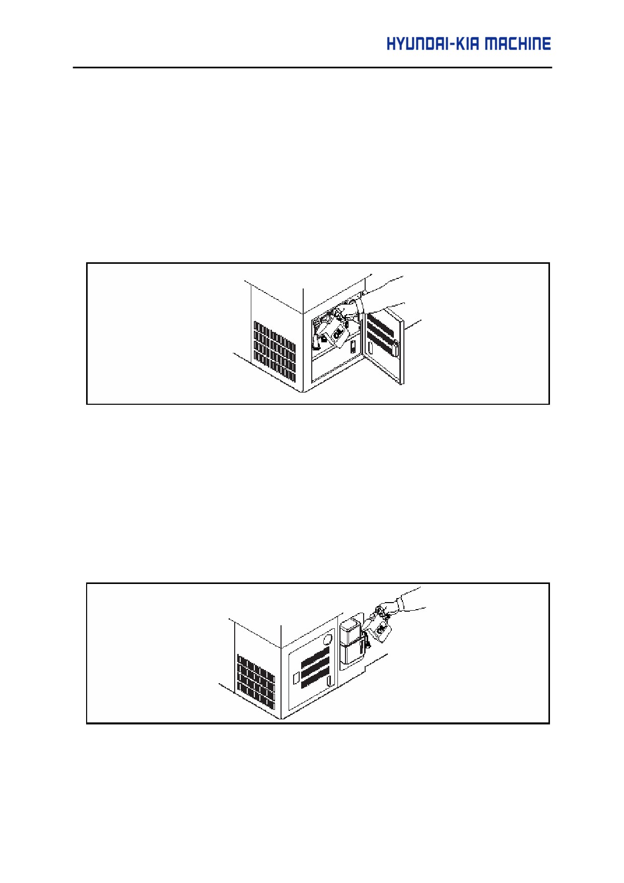
Perform oiling at the positions as shown in Figs. 4-7, 4-8 and 4-9.
(2)
Table 4-1 shows the recommended lubrication and oiling.
7-1.
Hydraulic Oil
1)
Fill up the quantity of oil to the degree higher than that of oil gage (After filled up, it is
recommended that the level is met with the standard level of oil gage).
2)
Quantity of oil is 15 liter(3.92 gal).
Fig. 4-7 Filling Hydraulic Oil
3)
After this, perform oiling as specified.
7-2.
Oiling Wet-Moving Parts in the X-and Z-axes
1)
Fill oil the lubrication tank in front of bed.
2)
The quantity about 1.8 liter(0.47 gal).
3)
If the oil is exhausted in the tank, the red lamp will be illuminated on the Operating Panel.
Then, fill it up.
Fig. 4-8 Filling Lubrication Oil
4-13
7-3.
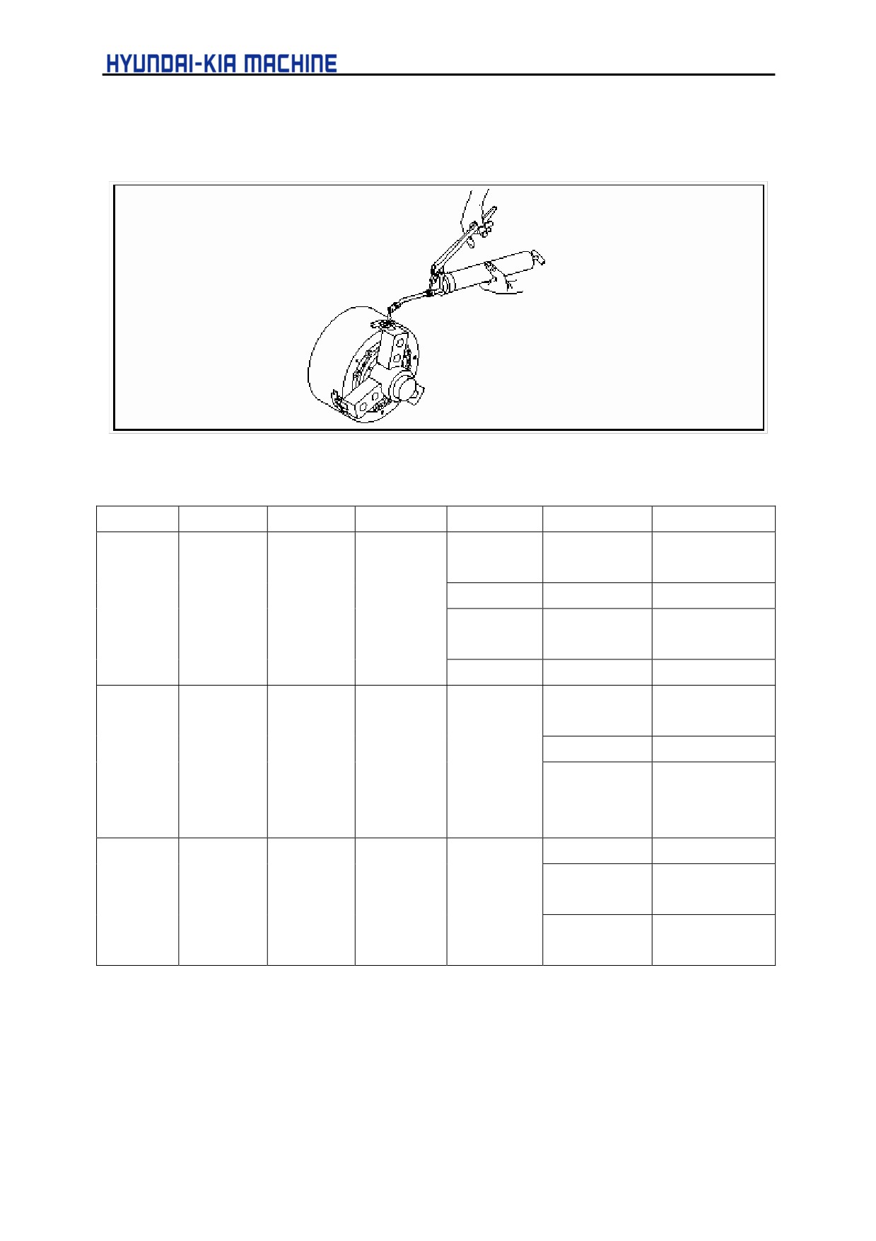
Oiling Hydraulic Chuck
•
Fill up the chuck daily while opening and closing it by means of the grease gun.
Fig 4-9 Greasing Chuck
Table 4-1. Lubrication Oiling Table
Place
Method
Quantity
Period
ISO Spec.
Maker
Used Oil
CB32 or
SHELL TELLUS
SHELL
HL32
OIL C32
Hydraulic
ESSO
TERESSO 32
Half-Yearly
tank
MOBIL DTE OIL
MOBIL
LIGHT
CALTEX
FBK OIL RO32
SHELL TONA
SHELL
If the
OIL T68
Wet
lubrication
ESSO
FABIS K-68
moving
G68
lack lamp
MOBIL
part
illuminated
MOBIL
VACTORA OIL
No.2
SHELL
ALBANIA 2
Manual
Daily More
DOW
MOLY KOTE
Hydraulic
Oiling
fully
than one
CC460
CORNING
BR2-S
chuck
Grease
time
MOBILUS
Gun
MOBIL
GREASE 2
4-14
IV. TRANSPORT & INSTALLATION
8.
Coolant
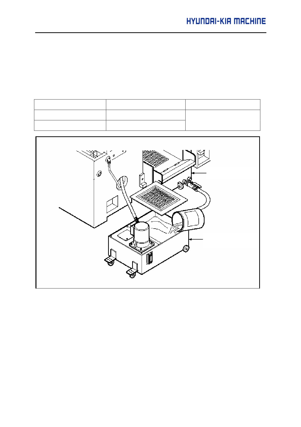
There are several kinds of coolant such as soluble and insoluble ones. The methods of filling
coolant into the machine are as follows.
(1)
Fill coolant into its tank in the rear of machine.
(2)
Total quantity of coolant is 135 liter.
Name
Quantity
Total Quantity
Coolant main tank
92 liter(24 gal)
135 liter(35.23 gal)
Coolant auxiliary tank
43 liter (11.23 gal)
Coolant Main Tank
Coolant Auxiliary Tank
Fig. 4-10 Filling Coolant
(3)
When installing the machine, performing test operation or having not used for long-term,
use the spare sufficiently.
4-15
(4)
Notice When Using Soluble Coolant
1) When selecting soluble coolant, select one in consideration of the lubrication, settlement,
anticorrosive, foaming device, unfixing with oil, safety, and so on.
2) Before starting or after stopping the work, remove chips and clean up soluble coolant
attached on each wet moving part, tool post turning part, and cross slide.
After that, always apply lubrication oil lightly.
3) Exchange the soluable coolant if corroded.
CAUTION
1.
Because soluable coolant is anti-corrosive treated, it is good in wet condition but easy to be
corroded in a dry state. After a completion of work, do not forget to apply anticorrosive oil on
the wet moving part.
2.
The soluable coolant has an alkalis factor and may remove fat from the personal skin. So, be
careful of worker' s health.
3.
For the dilution method and agent of soluable coolant, follow the manufacturer's instruction
because they are different dependent on its kind.
4)
For the dilution method and agent of soluable coolant, follow the manufactures's instruction
because they are different dependent on its kind.
9.
Electric Power and Wiring
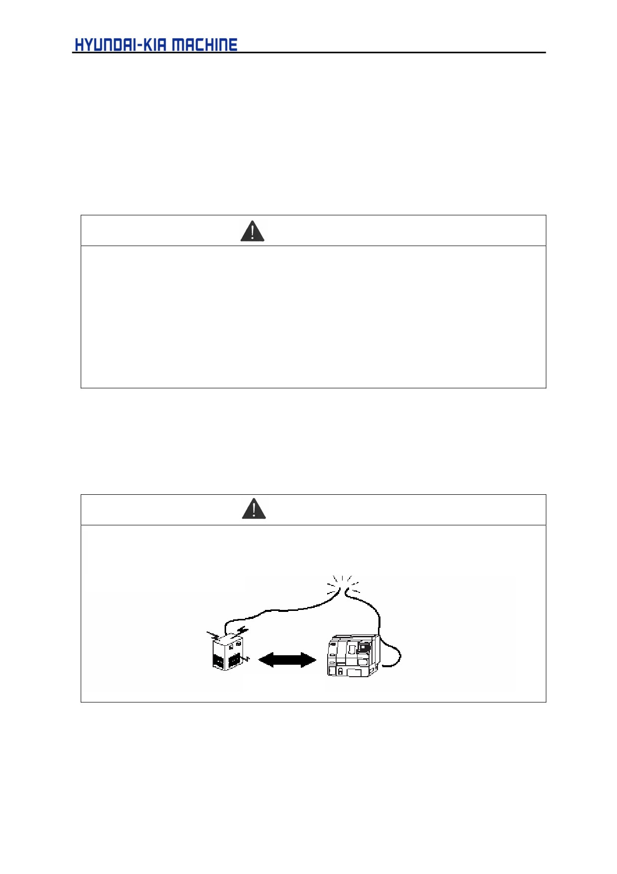
CAUTION
For the electric device (welder, high-frequency seasoning device, electric spark machine, and
etc.) occurring high-frequency noise, use the independent switchboard or install it away from over
20m.
Over 20m
4-16
IV. TRANSPORT & INSTALLATION
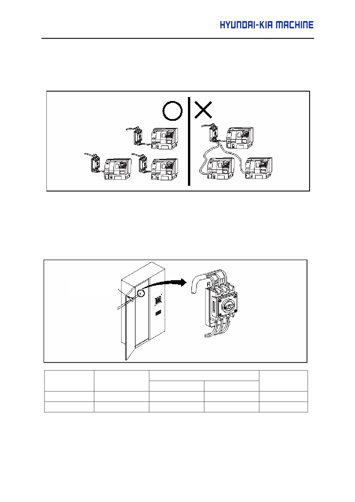
9-1.
Power Switch
Install other machines with the independent power switches at the place where easy to open and
close. See the following table for the capacity of fuse.
9-2.
Wiring To Machine Form Power Switch
Perform wiring to the 1st NFB1 through leading hole located in the lower left of the Electric Control
Panel. For the thickness of wire, see the following table and connect if so far the R.S.T not to be
changed.
Leading Hole
Model
Power Capacity
Available [mm*]
Fuse [A]
(kVA)
R, S, T
Grounding line
SKT100
11.4
14
14
75
SKT200
14.1
16
14
75
4-17
9-3.
Changing Electric Units According to Voltage and Frequency
CAUTION
If the voltage fluctuated seriously, it may cause misoperation of the machine and failure of the electric
and electronic parts. Therefore, set the fluctuating rate not to exceed ± 10%.
According to the voltage and frequency of the power of factory, it is needed to change the setting
of electric applications. Prior to changing, check its voltage and frequency.
1) Power voltage 200/220V ± 10%
2) Power frequency 50/60Hz ± 1Hz
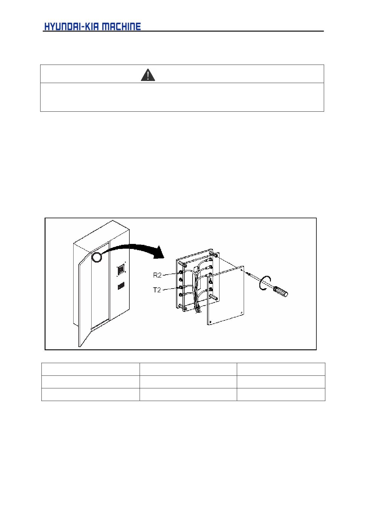
9-3-1. Tab Changing for Controlling Transformer
Open the door of the Electric Control Panel, remove the plastic cover of Transformer and then
change the wiring as shown in the following table.
Voltage
R2
T,
191-210 V
200 V
0 V
211-240 V
220 V
0 V
4-18
IV. TRANSPORT & INSTALLATION
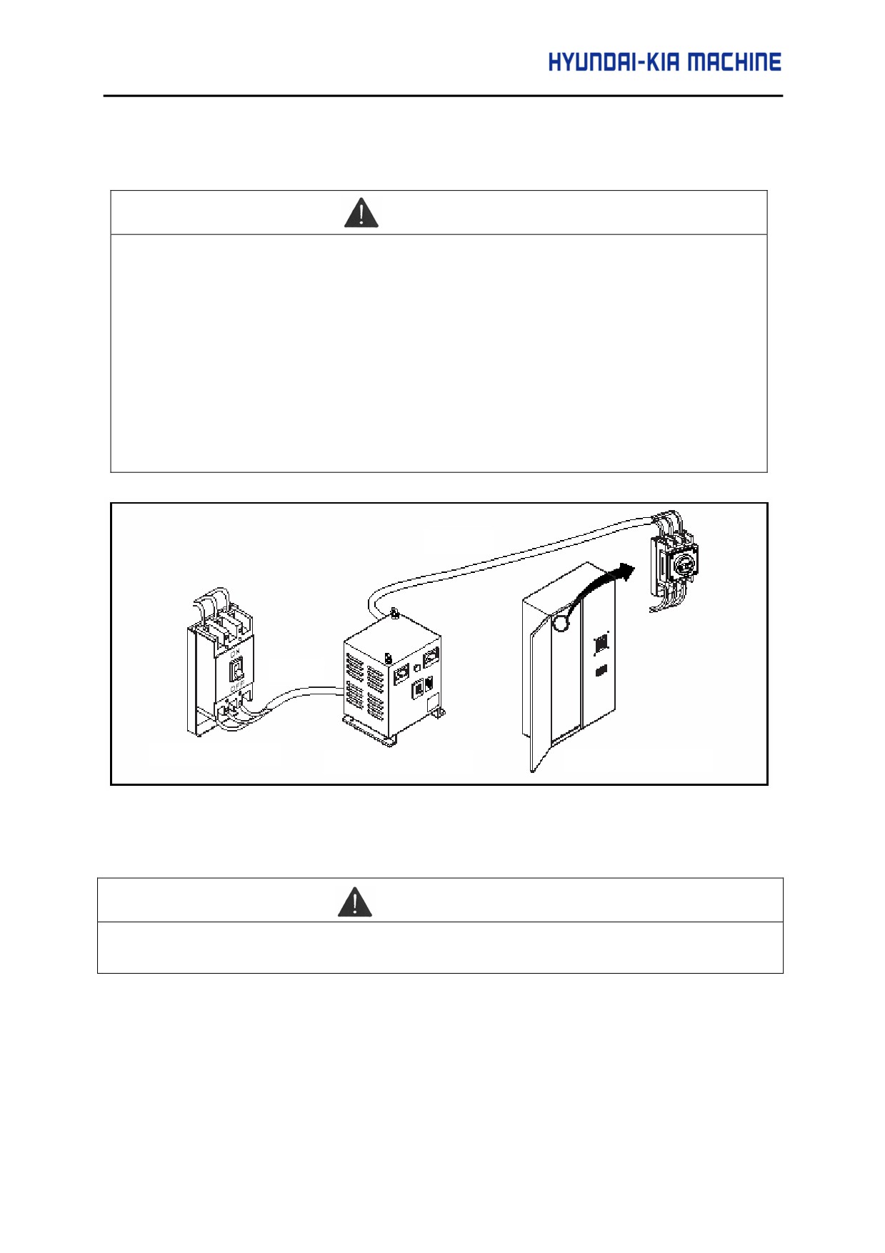
9-3-2. External Transformer
CAUTION
Transformer for 220V power supplier
The transformer should be installed by the customer' s direct purchase. This company
can't provide any external transformer for the 220V power supplier.
But the specific feature of a transformer should follow as below.
1)
Available only to EN 60742 (Please use authorized products)
2)
Feature
- Capacity : Above 25(KVA)
- Voltage - Primary : 380~440(V)
- Secondary : 200~220(V)
OUTPUT
INPUT
Power Supply Switch
External Transformer
Electric Box
9-4.
Grounding
WARNING
Only authorized engineer can do earth working. Failure to comply may result in personal severe injury,
death, or accident.
1)
All electric devices should be grounded to prevent personal injury and misoperation of
the machine according to the specification, after installed.
2)
Select the grounding point as close to the machine as possible and perform wiring
independently.
4-19
3)
Do the third-Class grounding only by the authorized engineer,
a.
The third-Class grounding
-
Thickness of wire : under 100 Ω
-
Thickness of wire : 1.5 times as that of power supply in thickness.
At least 14mm2
-
Measuring device : 500V Megger
4).
Grounding Method
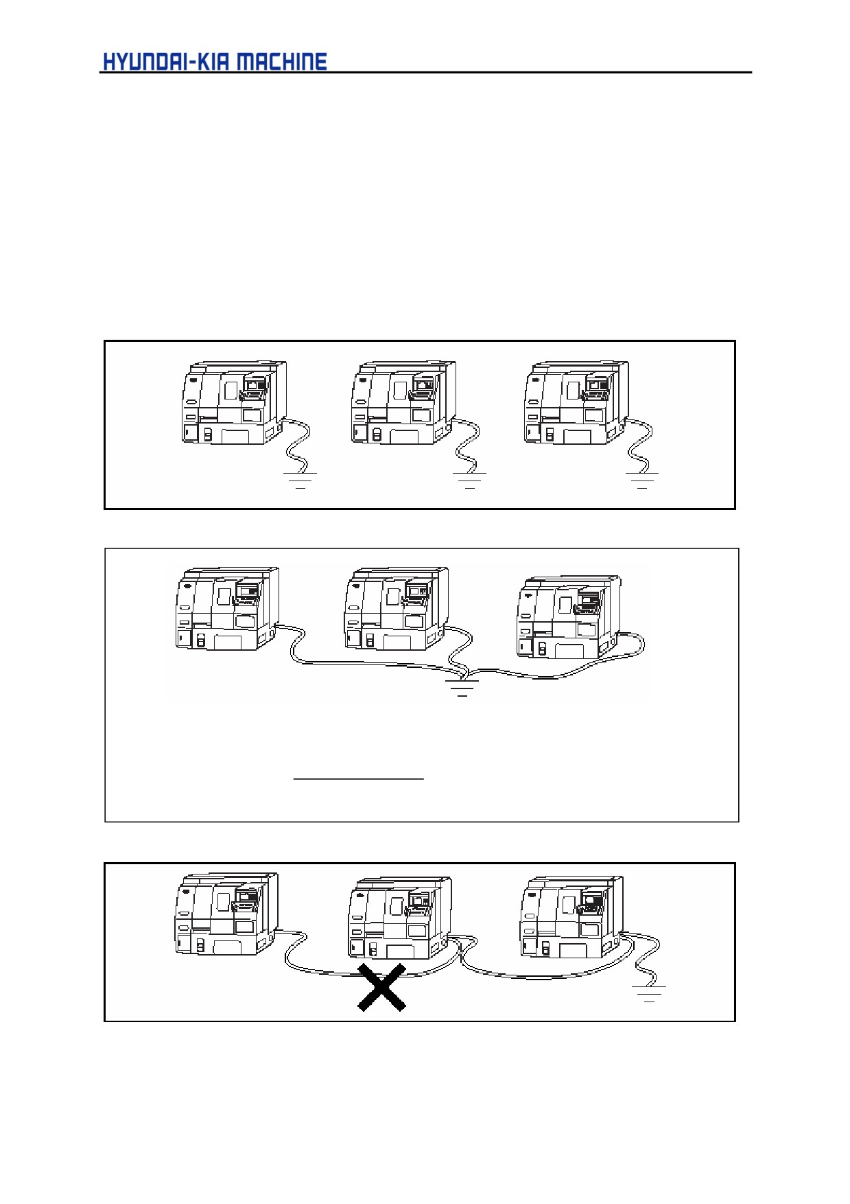
The machine should be grounded by one of the following methods,
a.
Individual grounding
b.
Common grounding
* The grounding line of each machine should be grounded at its ground terminal
directly.(Only one line to one terminal)
* Grounding resistance =
100
[Ω]
number of machine
c.
Never ground in the following methods.
4-20
IV. TRANSPORT & INSTALLATION
10.
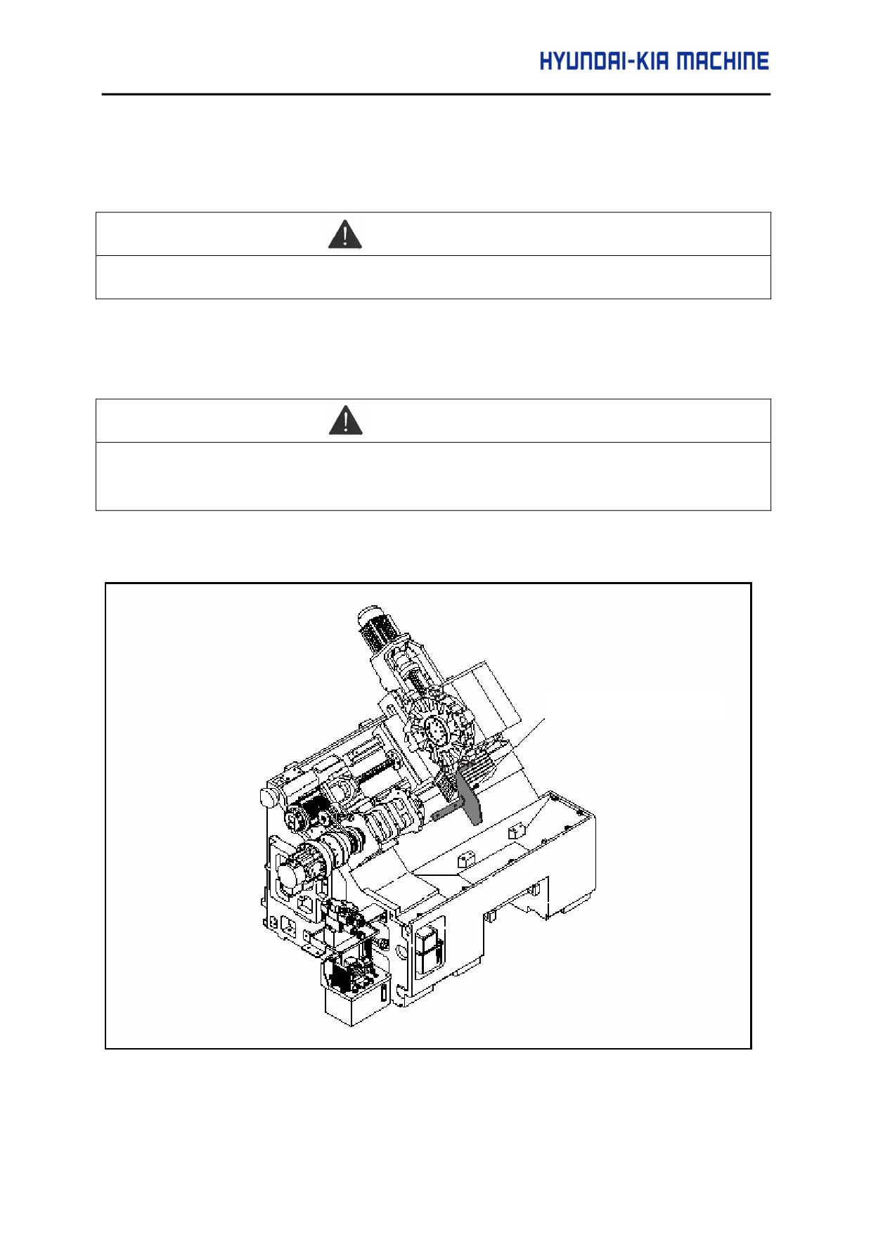
Disassembling and Cleaning Shipment Fixture
When shipped, each axis is fixed by shipment fixture for a safety.
WARNING
NEVER operate the machine before disassembling the shipment fixture.
After disassembling the shipment fixture, unless otherwise stated, clean the applied anticorrosive
agents with light or cleaning oils and apply the cleaned part with lubricating oil for sliding.
CAUTION
Do not use oil or kinds of chemicals which may affect the painting of body. Be careful of a fire.
The location of the shipment fixture is shown in the following figure (yellow painting).
Shipment Fixture(Yellow)
4-21
11.
Checking Before Test Working
Before test working, make sure the followings.
(1)
Check all the fixtures for transport or shipment are removed.
(2)
Check any part or accessory is omitted.
(3)
Check the lubricating, operating oil, and coolants are supplied properly.
(4)
Check the coolant tank is located properly.
12.
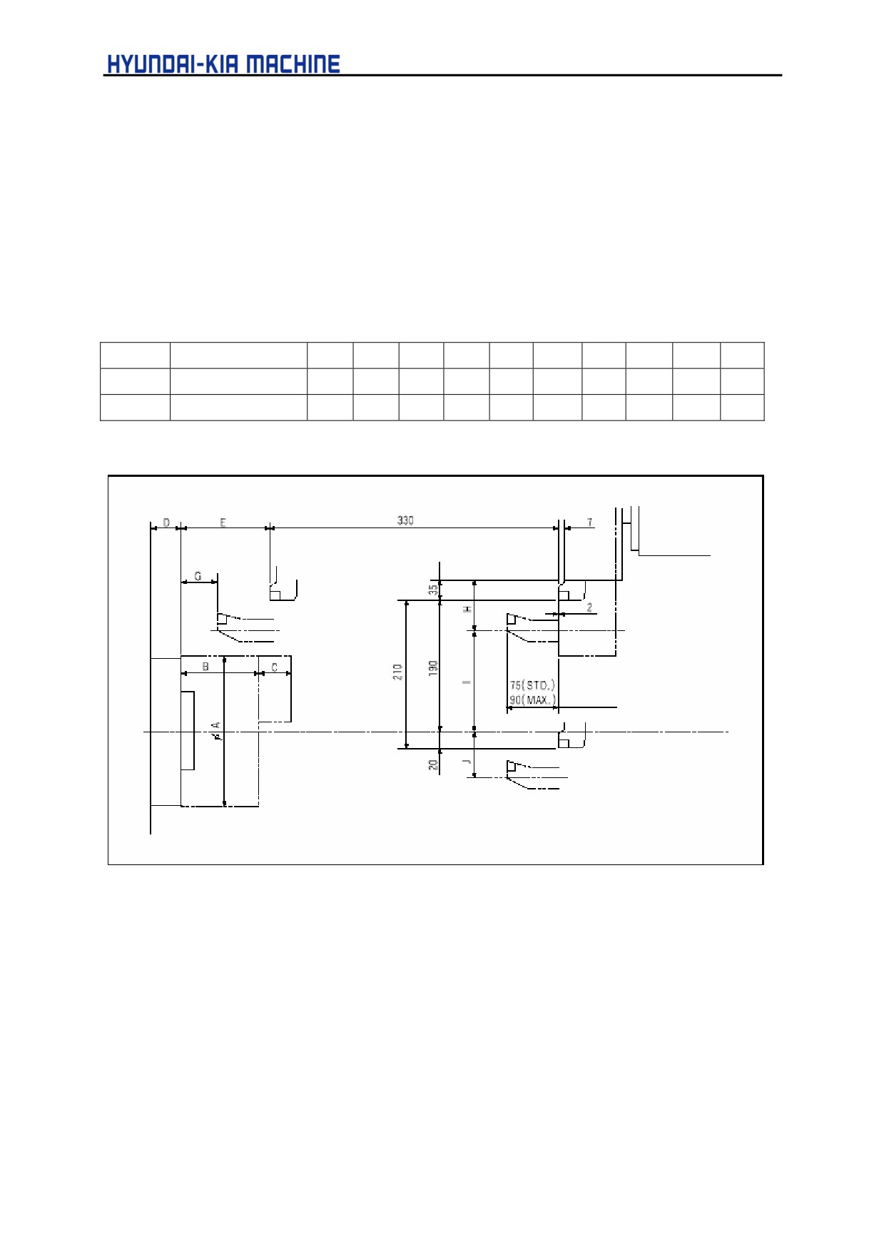
Required Dimension In Working 12-1. Tool Moving Range
•
Variable array tool post stroke
mm
Type
Tool Post
A
B
C
D
E
F
G
H
I
J
SKT100
12 angle spec.
169
91
32
35.2
91
185
18
35
190
20
SKT200
12 angle spec.
210
114
38
42.1
120
190
47
68
157
53
4-22
IV. TRANSPORT & INSTALLATION
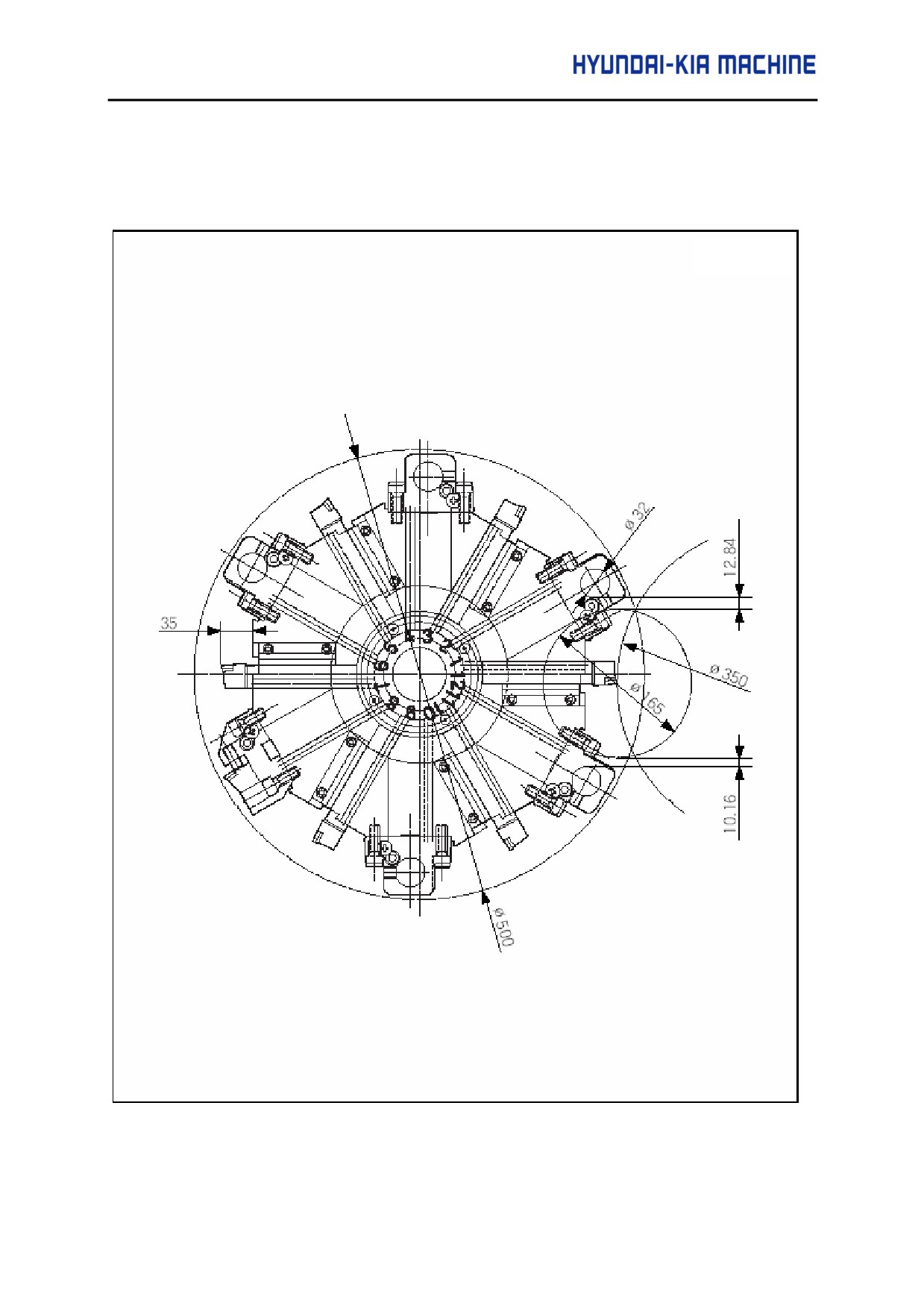
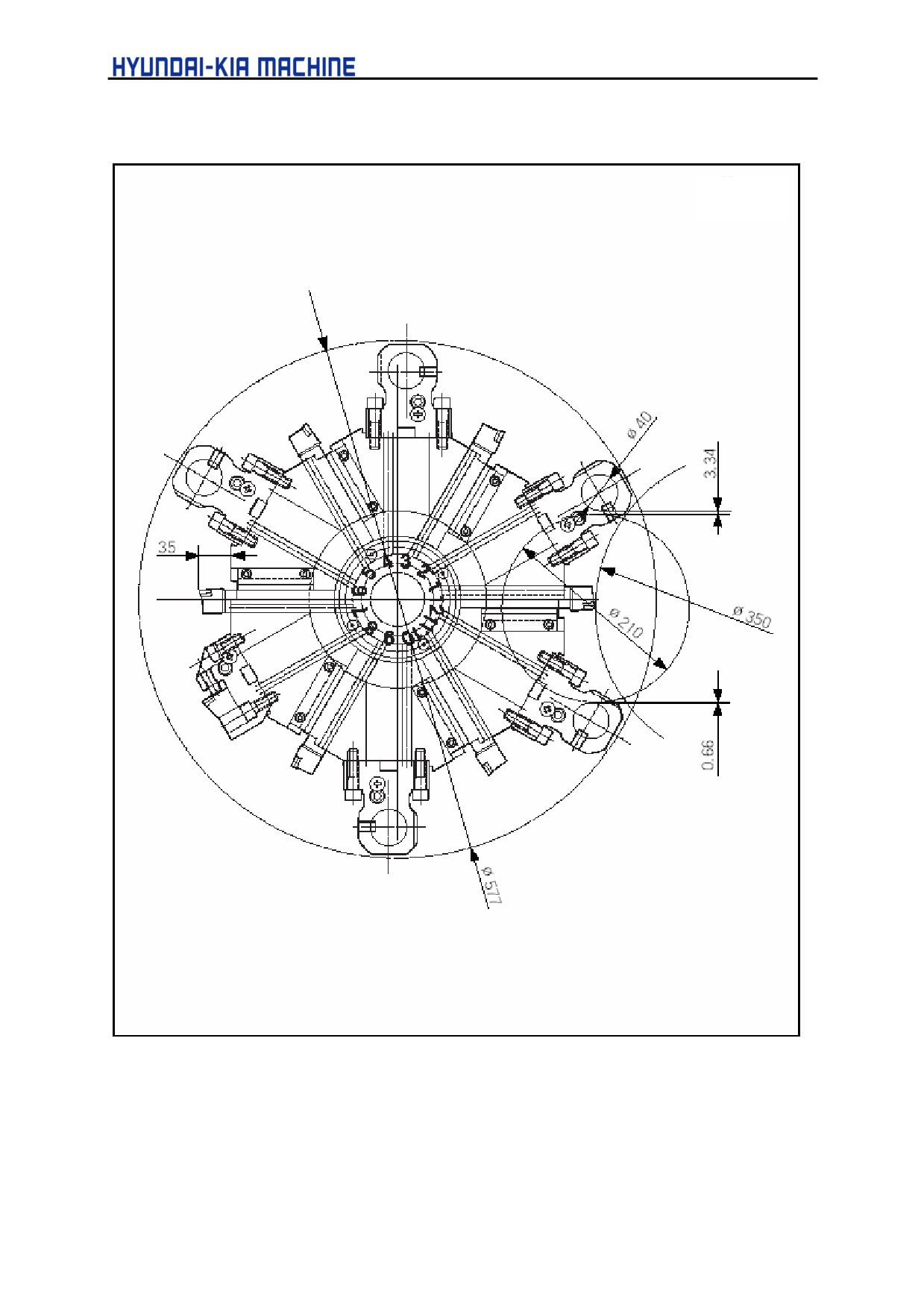
12-2. Tod Interference Diagram
1)
SKT100 Interference Diagram
Unit: mm
4-23
2)
SKT200 Interference Diagram
Unit: mm
4-24
V
REPAIR & PRESERVATION
V REPAIR & PRESERVATION
1.
Mechanical Overview
5-1
1-1. Mechanical Construction
5-1
1-2. Moving Range of Axis
5-2
1-3. Reference Point Adjustment of Each Axis
5-3
1-3-1. Reference Point Adjusting Method 1
5-3
1-3-2. Reference Point Adjusting Method 2
5-7
1-3-3. Z-axis Dog and Limit Switch Attached Position
5-15
1-4. X- and Z-axes Backlash Adjusting Method
5-16
1-5. Q-Setter Position Adjustment
5-18
2.
General Check and Repair
5-21
2-1. General
5-21
2-2. Check and Repair Items
5-23
2-3. Daily Check and repair
5-24
2-3-1. Inside of the Machine
5-24
2-3-2. Outside of the machine
5-26
2-3-3. Checking Oil Flow
5-27
2-3-4. Checking Pressure
5-28
2-3-5. Filling and Changing Oil
5-29
2-3-6. Around the Machine
5-31
2-4. Weekly Check and Repair
5-31
2-4-1. Inside of the Machine
5-31
2-4-2. Outside of the Machine
5-32
2-5. Monthly Check and Repair
5-33
2-5-1. Inside of the Machine
5-33
2-5-2. Filling and Changing Oil
5-34
2-5-3. Outside of the Machine
5-36
2-6. Six-monthly Check and Repair
5-36
2-6-1. Filling and Changing Oil
5-36
2-6-2. Around the Machine
5-40
2-7. Yearly Check and Repair
5-45
2-7-1. Around the Machine
5-45
2-8. Check and Repair Before Long-term Storag
5-46
2-9. Check and Repair Before Operation Since Long-term Storage ... 5-47
3.
Maintenance of Major Units
5-49
3-1. Spindle
5-49
3-1-1. Adjustment of Degree in Spindle
5-49
3-1-2. Cleaning Front Cover of Spindle
5-50
3-2. X- and Z-Axes
5-51
3-2-1. X- and Z-Axes Constructions
5-51
3-3. Tool Post
5-52
3-3-1. Tool Post Construction
5-52
3-3-2. Tool Post Home Position Setting
5-52
3-3-3. Adjustment and Exchange of Clamp, Unclamp
and Limit Switches
5-55
3-3-4. Restoration in Collision of Turret
5-56
3-4.
Hydraulic
5-57
3-4-1. Hydraulic Circuit Diagram
5-57
3-4-2. Repairing Hydraulic Tank
5-58
3-4-3. Pressure and Flow Adjustment
5-60
3-4-4. Repairing Manifold
5-62
3-5.
Lubrication Device
5-66
3-5-1. Place to be lubricated
5-66
3-5-2. Cleaning Lubrication Unit
5-67
3-5-3. Discharge of Lubricating Oil
5-70
3-6.
Coolant
5-71
3-6-1. Coolant Unit Construction
5-71
3-6-2. Specification and Cleaning
5-72
3-6-3. Check and Repair
5-74
3-7.
Chuck and Cylinder
5-75
3-7-1. Chuck and Cylinder Construction
5-75
3-7-2. Adjustment
5-76
3-7-3. Specification
5-77
3-8
Cover
5-80
3-8-1. Door Roller
5-80
3-8-2. Door Safety Glass
5-81
3-9.
Electricity
5-82
3-9-1. Electric Device Layout
5-82
3-9-2. Alarm Lamp (Option)
5-82
3-9-3. Alarm Indicator
5-83
3-9-4. Parameter
5-86
3-9-5. Exchanging Method of Battery
5-87
3-9-6. Error Codes (Serial spindle)
5-96
3-9-7. Alarm List
5-104
V. REPAIR AND PRESERVATION
1.
Mechanical Overview
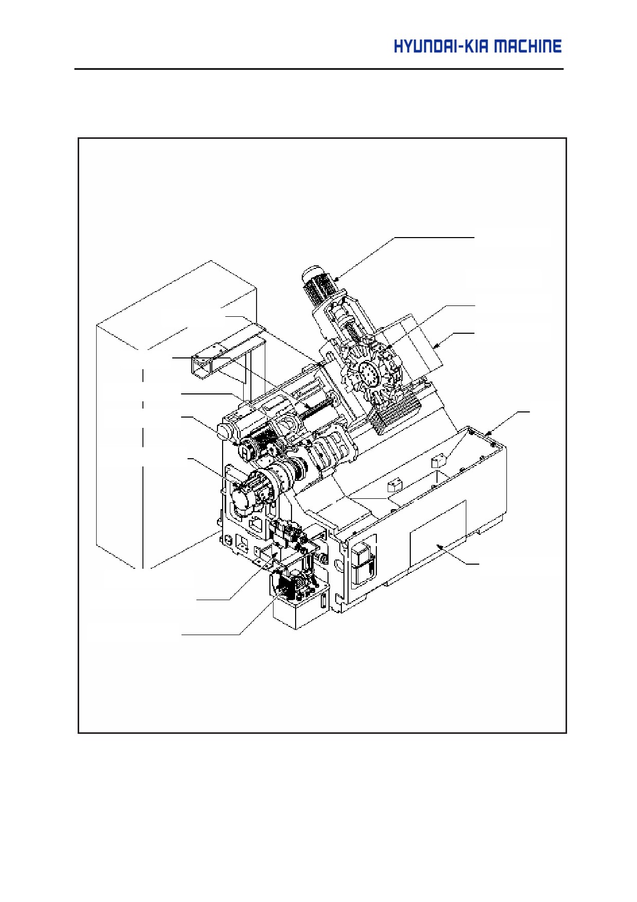
1-1. Mechanical Construction
X-axis Motor
X-axis Motor
Turret
Saddle
Tool Post
Z-axis
Head Stock
Bed
Z-axis Motor
Rotary Cylinder
Coolant Tank
Spindle Motor
Hydraulic Manifold
Hydraulic Motor
Fig. 5-1 Mechanical Construction - Major Unit
5-1
1-2. Moving Range of Axis
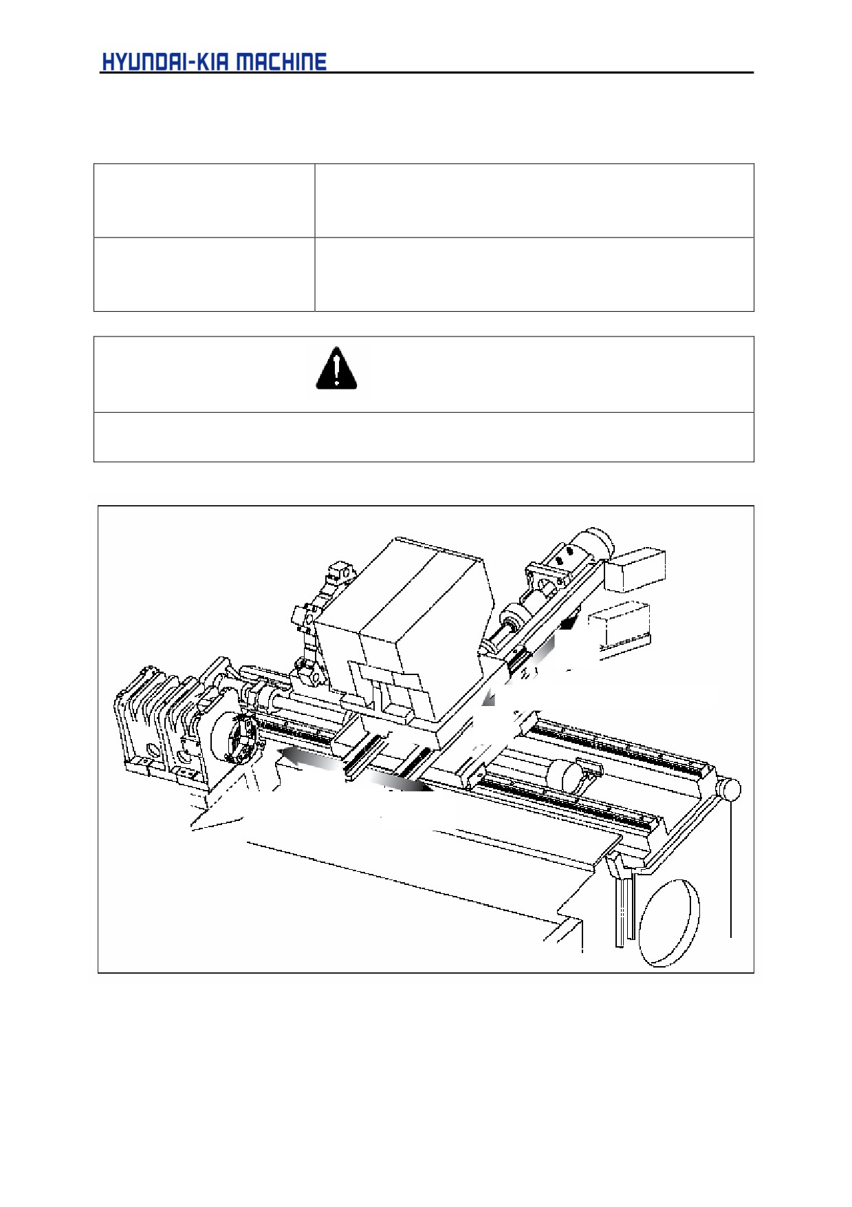
X-Axis Up/Down direction vertically with the center of spindle
X-Axis
+: in tool post upward
-: in Tool post downward
Z-axis Up/Downward direction horizontally with the center spindle
Z-axis
+: in the right direction of tool post movement
-: in the left direction of tool post movement
CAUTION
It is based when the operator spindle stands in front of the machine.
- direction X-axis
+ direction
- direction Z-axis
+ direction
Fig. 5-2 Moving Range of Axis
5-2
V. REPAIR AND PRESERVATION
1-3.
Reference Point Adjustment of Each Axis
Reference point may be changed and resetted for repairing and checking or due to the collision
of tool post. This time, the reference point should be adjusted in the following orders.
CAUTION
Reference point is the unique position determined by the parameter of NC device and the dog & limit
switch of machine.
1-3-1. Reference Point Adjusting Method 1
In case that "[MACHINE(ABSOLUTE)]" coordinate value is less than reference point, adjust it in
the following method.
1) Initiate running distance
Initiate the Reference Point Return Running Distance entered.
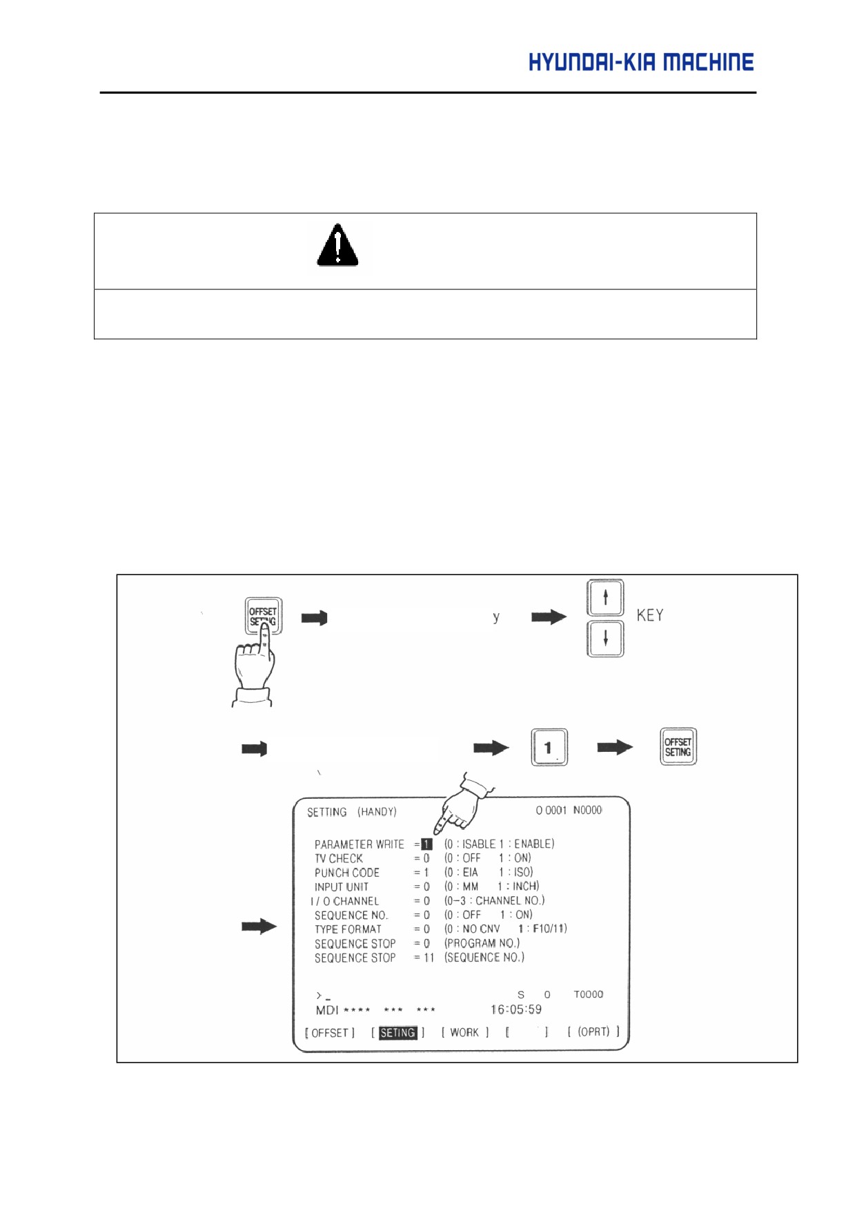
a. Select the setting screen and make the parameter change valid.
Press [SETTING] key
PARAMETER WRITE
5-3
b. Initiate the Reference Point Return Distance by selecting parameter screen.
c. Make parameter change invalid, turn off and then re-apply the power.
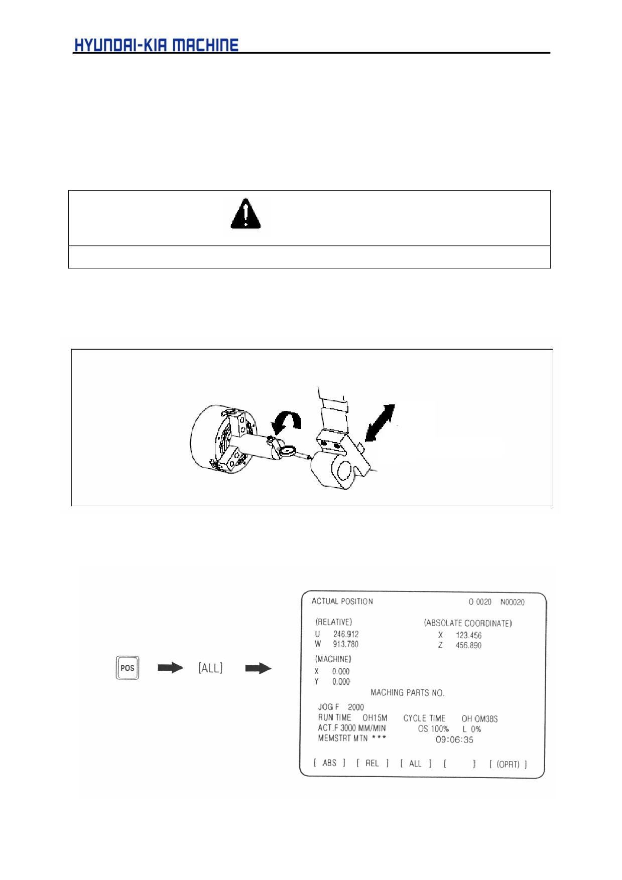
2) X-Axis Reference Point Adjustment
a. Attach Dial Gauge(1/100) at holder and then secure in chuck.
CAUTION
If using Magnet Stand instead of Fixture, it may be curved over 0.1 mm.
b. Put the indicator near to I.D base holder using feed handle and set the motion to "0" in
the X direction.
Xy direction
c. Select the package position screen.
5-4
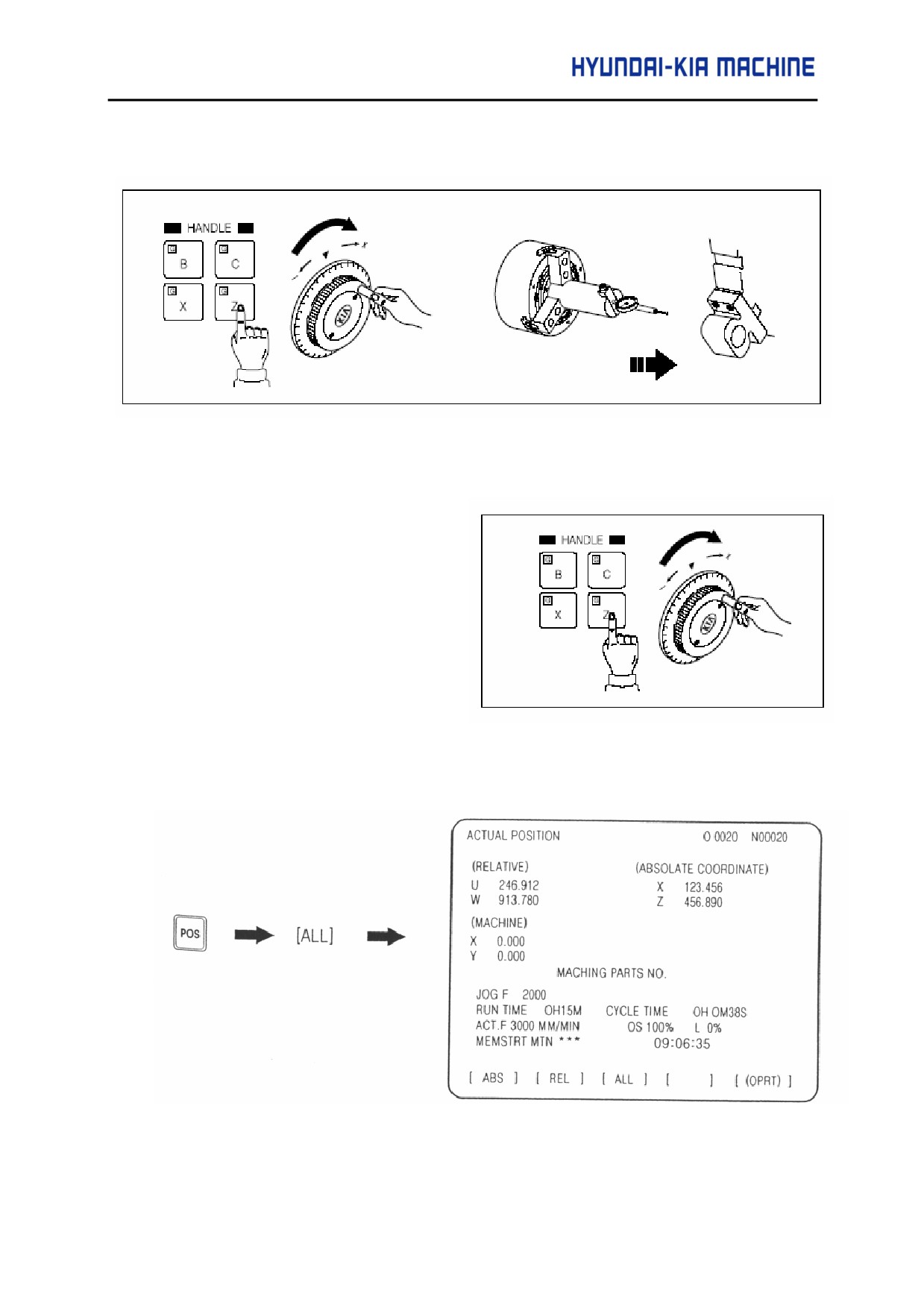
V. REPAIR AND PRESERVATION
d. Set the mode to Handle Z, move the Head Stock in the + direction of Z-axis
e. The differences between reference point position in X-axis and the coordinate value of
MACHINE become a running distance.
3) X-Axis Reference Point Adjustment
a. To approach the outer diameter
bite tool to chuck and protect the
blade end, use a thin piece of
paper, feed the handle and
approach the tip end of bite tool
to the jaw section until the paper
is not moved.
b. Select the package position screen.
5-5
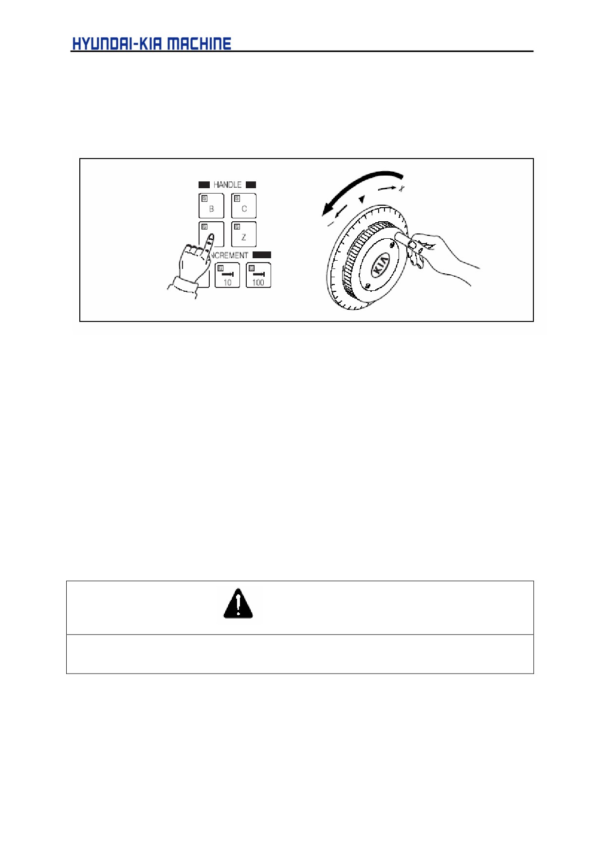
c. Set the mode to Handle X, move the turret head in the + direction of X-axis, and make
it not to disturbed in Tail Stock (Special Accessory).
d. The differences between reference point position in Z-axis and the coordinate value of
MACHINE become the grid shift amount.
4) Input Running Distance
a. Make the parameter change valid according to para. 1).
b. Calculate the running distance
If the [MACHINE] coordinate is set to 377.268 and 332.754 for 380.000 in the X-axis
and 330.000 in the Z-axis, the running distance of each axis will be calculated as
follows.
• X-axis distance = initial value + (380.000-377.268) X1000
= 1000+2732 = 3732
• Z-axis distance = initial value + (330.000-322.754) x 1000
= 1000+7246 = 8246
CAUTION
In case that "MACHINE" coordinate value is more than the reference point distance, it is required to
adjust the deceleration dog.
c. Change the parameter.
5-6
V. REPAIR AND PRESERVATION
1-3-2. Reference Point Adjusting Method 2
In case that "MACHINE (ABSOLUTE)" coordinate value is more than the reference point
distance, adjust in the following method.
1) Initialize running distance
Initialize the running distance as in "Zero Adjusting Method 1", turn off and then re-apply
the power.
2) X-axis
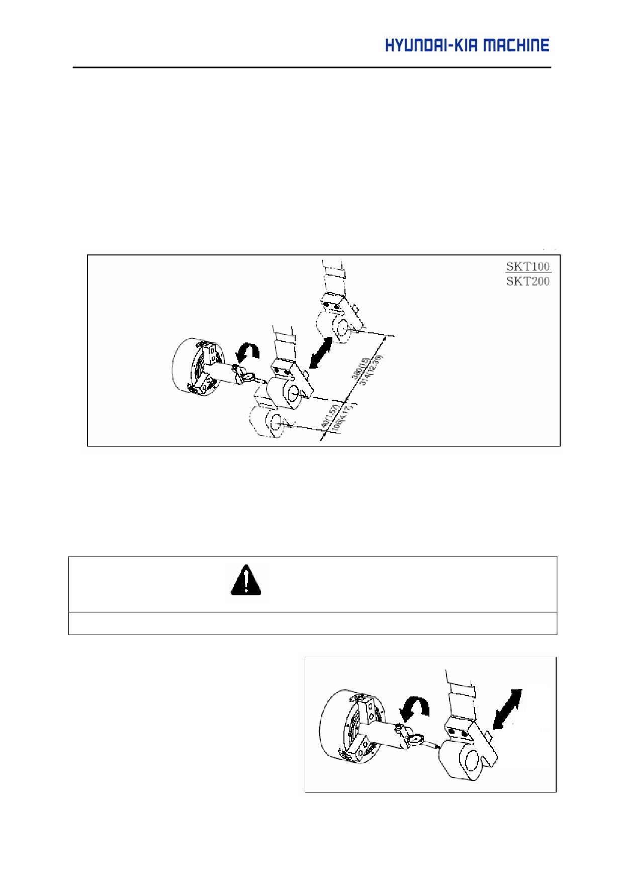
mm(in)
Fig. 5-3 Moving Range of X-axis
Set the distance to the center of spindle from that of I.D. Base holder from that of spindle at
380.000 (SKT100) and 314.000 (SKT200) in the + direction.
a. Attach Dial Gauge (1/100) at holder and then secure in chuck.
CAUTION
If using Magnet Stand instead of Fixture, it may be curved over 0.1 mm.
b. Make I.D. base holder in
proximity to indicator using
feed handle and set the motion
in X direction to "0".
Xy direc-
tion
5-7
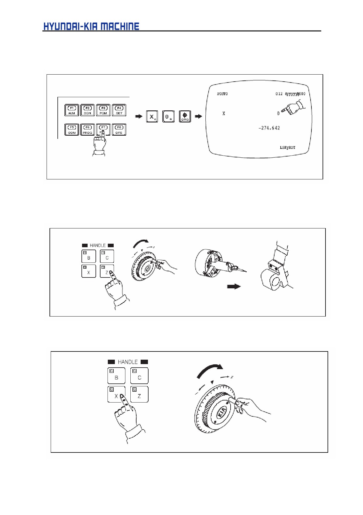
c. Set the coordinate "X" to "0
d. Set the mode to Handle Z, move the turret head in the + direction of Z-axis and make
it not to be interfered with Tail Stock.
e. Move the X-axis to reference point by means of handle.
5-8
V. REPAIR AND PRESERVATION
CAUTION
1.
Perform only in X-axis.
2.
Place Z-axis at a distance from reference point.
f.
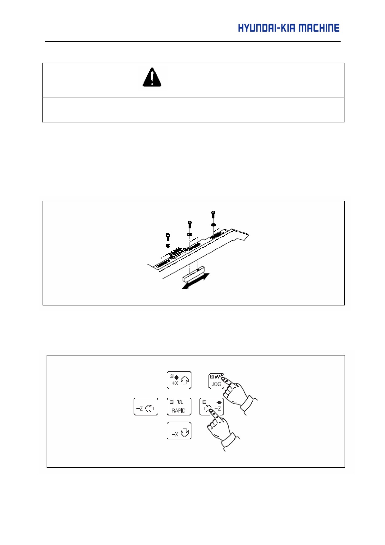
This time, move the current position "EXTERNAL" coordinate to be 380.000 (SKT100) and
314.000 (SKT200), set the coordinate X at "0" and then move it about 1/2 (6,000) of ball
screw pitch in the opposite direction from Reference Point Return.
g. Move the reference point return dog to the position where the reference point reduction
signal is turned ON.
Fig. 5-4 Reference Point Return Dog Movement
h. Reference point return the X-axis.
5-9