Hyundai SKT 100/200 CNC TURNING CENTER. INSTALLATION MAINTENANCE MANUAL (VERSION No.: VOL1.0) - page 1
SKT 100/200 CNC TURNING CENTER
INSTALLATION
MANUAL
MAINTENANCE
(FANUC Oi-TB)
VERSION No.: VOL1.0
1680MAE01F1
2003. 6.
Contents
I.
INTRODUCTION
1-1
II. SAFETY
2-1
III. SPECIFICATION
3-1
IV. TRANSPORT & INSTALLATION
4-1
V. REPAIR & PRESERVATION
5-1
I INTRODUCTION
1. Outline of The MANUAL
1-1
1-1. Symbol and Description
1-2
2. Characteristics
1-3
3. Standard Accessory
1-3
4. Special Accessory
1-4
I. INTRODUCTION
1.
Outline of the Manual
This manual contains the followings for a proper use and overall understanding of this machine.
(1) NC device Operation manual
Contains operating instructions.
(2) Installation & Maintenance Manual
Contains the periodic inspection an the installation and maintenance instructions.
(3) Parameter List
Contains detailed parameters.
(4) Alarm List
Contains detailed alarm informations.
(5) Part List
Contains the details required to purchase the part.
(6) Electric Circuit Diagram
Contains electric circuit diagram.
The record of values including the "parameter table" enclosed here should be kept as it is
necessary for maintenance and adjustment of machine.
Thank you!
1-1

1-1
Symbol and Description
(1)
This manual contains 7 chapters shown in the Roman numerals.
Ex)
I
INTRODUCTION
Title
Chapter 1
(2)
Each chapter contains several sections.
Outline of MANUAL
Ex)
1
Title
Chapter 1
(3)
A section contains several items
Ex)
1 - 1
Symbol and Description
Title
Item
Section 1
(4)
Each item contains several paragraph
Ex)
4 - 1 - 1
Installation Condition
Title
Paragraph
Item
Section 1
(5)
The figure and Table are shown in accordance with each "Chapter"
Ex)
Figure 3 - 7
Major Dimensions of Head Stock
Title
The seventh figure of Chapter 3.
Chapter 3
Ex)
Table 3 - 1
Specification
Title
The 1st table of Chapter 3
Chapter 3
1-2
I. INTRODUCTION
2.
Characteristics
This machine is two axis CNC lathe with drum type turret, and has the following features.
(1) Enables both chuck and center works.
(2) Uses AC built-in motor to directly change the speed in a wide range [5,5/7,5 kW (SKT100),
7,5/11 kW (SKT200)]
(3) Adapts the constant surface speed function as a standard option.
(4) Adapts the permanent set as a standard option, machines a variety of workpieces in the
same setting and uses the tool available in the market.
(5) Epoch-making reduction of the tool indexing time and the turret rotation speed by applying
the servo motor-driven tool post.
(6) Accurate positioning by using the advanced LM-guide and ball screw.
(7) The greatest feed rate (36m/min) of axis in the world.
(8) Minimized heat displacement in X-axis by double pre-tension structure.
(9) Stable bed structure of 45°.
(10) Ensures rapid and easier operating by applying the FAUNC Oi-TB CNC of 32 bit.
(11) High quality one with a beautiful color and the cover designed somatologically.
(12) Adding special accessories enable to maximize the request for automatization and higher
productivity.
3.
Standard Accessory
•
Ø 165 (6.5") hollow chuck & rotary cylinder (SKT100)
•
Ø 210 (8.3") hollow chuck & rotary cylinder (SKT200)
•
Leveling seat
•
Spanner & wrench
•
Soft jaw
•
Spindle override (50 ~ 150%)
•
Hydraulic unit
•
Foot switch (For chuck)
•
Auto-coolant device
•
Test report
•
Auto-lubricant device
•
Operation manual
•
Base holder for Inside (Internal
•
Chuck open/close M function
Diameter) tool
•
Work Light ON/OFF Switch
•
Sectional base holder
•
Work Light
•
Chuck open/close confirmation device
•
Spindle load meter
•
Door lock system
1-3
4.
Special Accessory
•
Auto door
• Chip conveyor (both for side and rear)
•
Spindle internal stopper
• Chip box
•
Spindle rpm meter
• Air blow
•
Work counter
• Coolant gun
•
Auto power cut off system
• Jet coolant
•
Integrating timer
• Spindle internal coolant
•
Weekly timer
• Chuck upper coolant
•
Workpiece attachment confirmation device
• TR robot
•
Spare tool call function
• KN robot
•
Rotary tool post
• Chuck open/close confirmation device
•
Sub spindle
• Tail stock For./Ret. foot switch
•
QCT tool post
• Chuck pressure 2nd stage converting device
•
CALL LIGHT (1, 2 or 3 colors)
• Spindle positioning device
•
Q-setter
• Tail Stock
•
Parts catcher
• Tail stock For./Ret. M function
1-4
II SAFETY
1.
General
2-1
2.
General Safety Precautions
2-2
3.
Notice When Operating Machine
2-6
4.
Notice When Repairing and Checking
2-10
5.
Notice on the Electric and NC Device
2-13
6.
Safety Device
2-15
6-1. Name Plates
2-15
6-2. Safety Device
2-16
II. SAFETY
1.
General
(1) The purpose of safety notice is to avoid personal injury or damage to the equipment from
accidental events.
(2) The expressions DANGER, WARNING or CAUTION used in this manual, have a special
meaning, which is stated below:
DANGER Failure to comply may result in personal death.
WARNING Failure to comply may result in personal severe injury or lethal
damage to the machine.
CAUTION
Failure to comply may result in personal light injury or damage
to the machine.
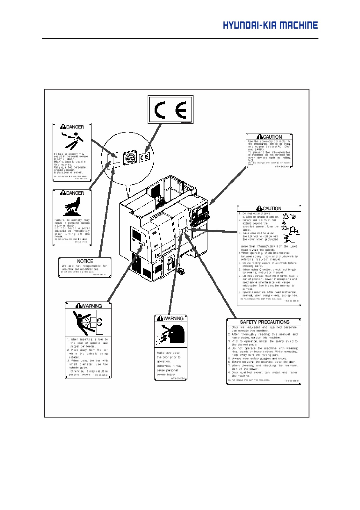
(3) Read and observe instructions of the name plate on the machine. Also, do not change the
position of the name plate or damage it. If broken, purchase it with the no. of item shown in
Part List.
(4) Before Servicing this machine, thoroughly be familiar with this instruction and the notice of
nameplate.
We're not responsible for damage due to your careless use.
2-1
2.
General Safety Precautions
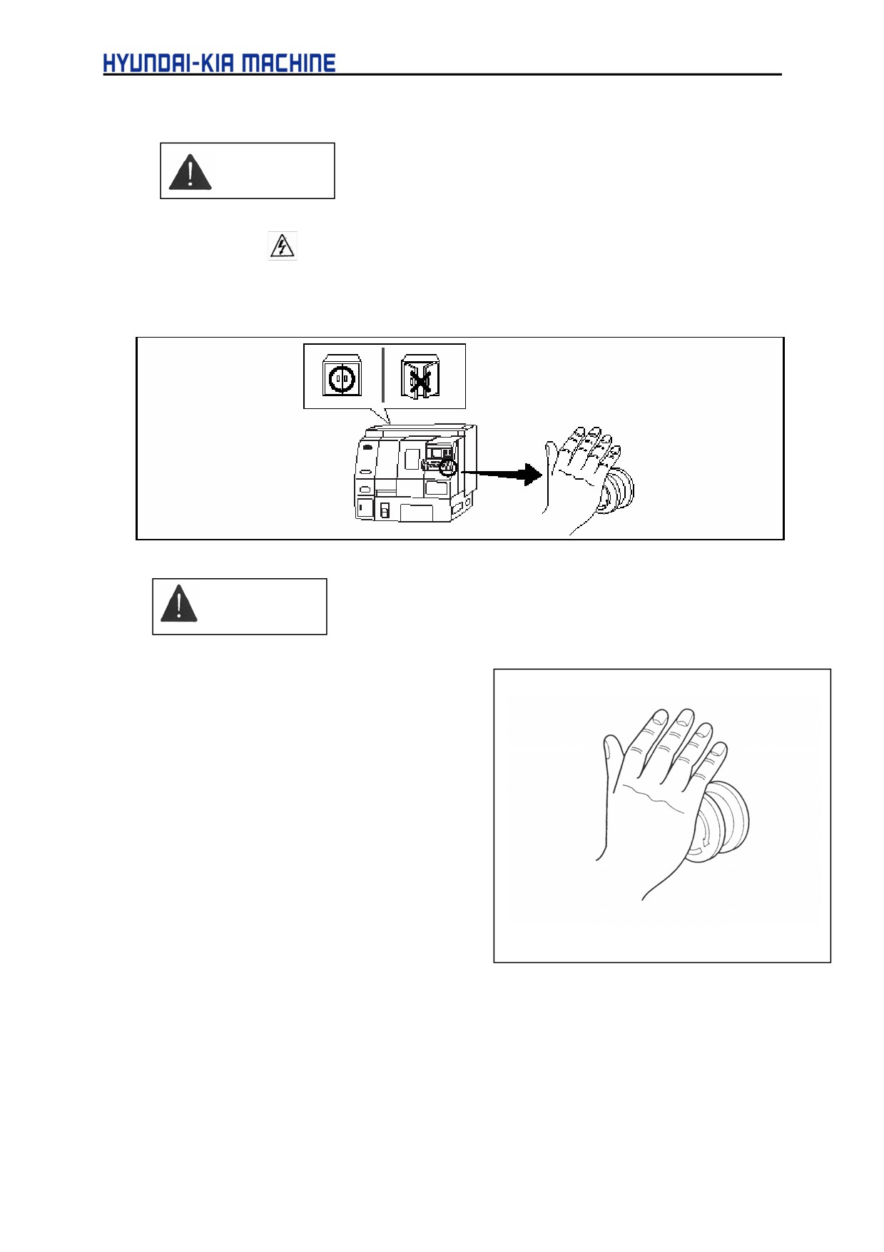
DANGER
(1)
Do not touch any device in the Electric Control Panel and Operating Panel and in which
the mark
is located.
(2)
Prior to operating the machine, always close the door and check if safety shield located.
If the door opened, immediately turn off the main power.
WARNING
(1)
Remember where the Emer-gency stop
switch is to operate it anywhere at all
times.
(2)
Before operating the machine, check if
the switches are functioned correctly to
avoid malfunction.
(3)
Never touch any rotating part or tool by
hands while operating.
(4)
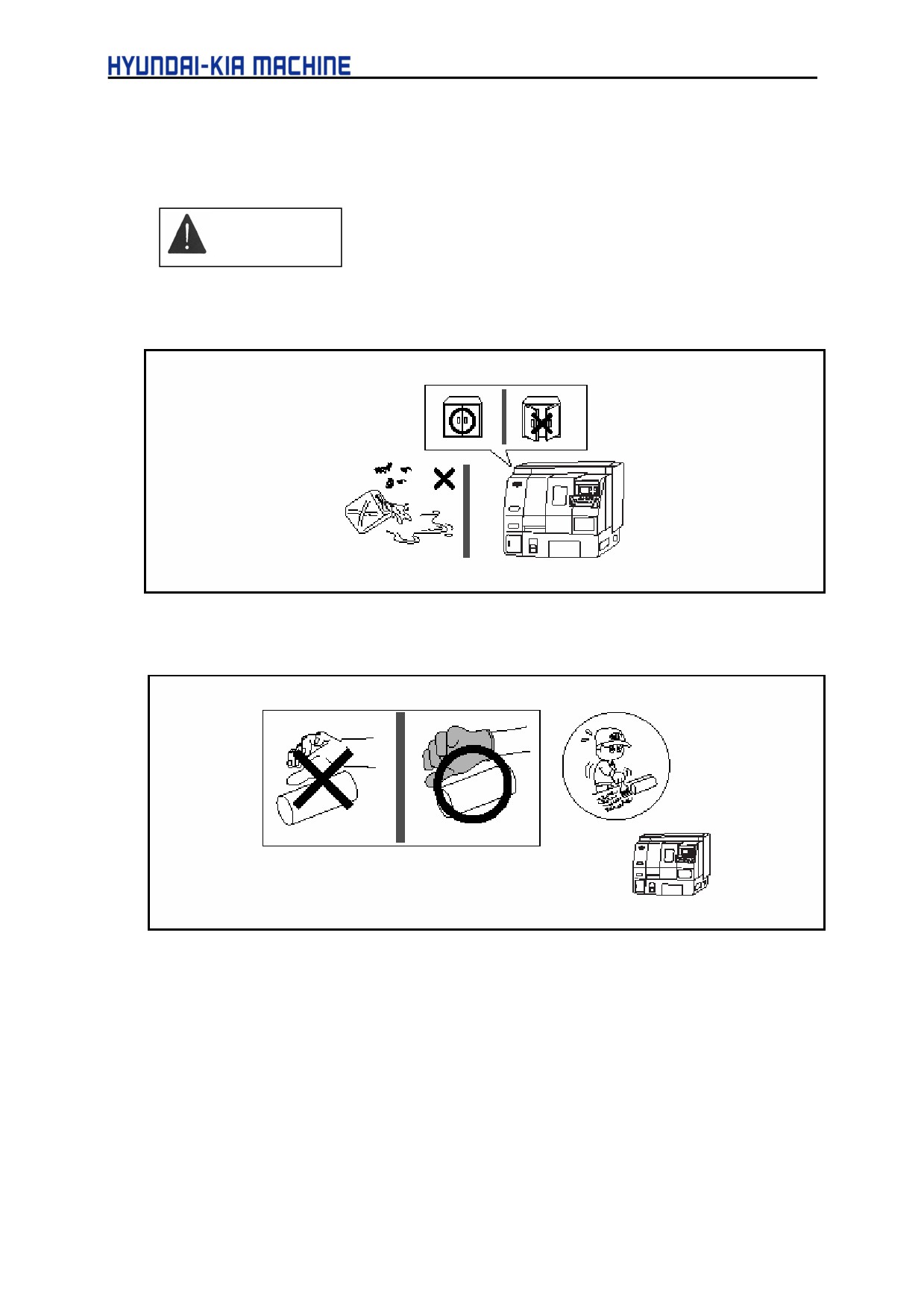
Remove oil and water left on the floor to
prevent workers from slipping.
(5)
Do not enter the inside of machine
Figure 2-1. Emergency Stop Switch
except for repairing work.
2-2
II. SAFETY
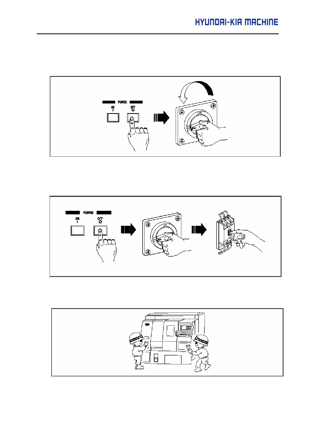
(6) When temporarily stopping a work and leaving the machine, first switch off the Operating
Panel and then the main power.
(7) When finishing a daily work and leaving the machine, switch off the Operating Panel, the
main power switch, and then the power supply switch at factory.
(8) It is dangerous to operate the machine when being operated or repaired by the other worker.
Be careful when more than two people have to work together.
2-3
(9)
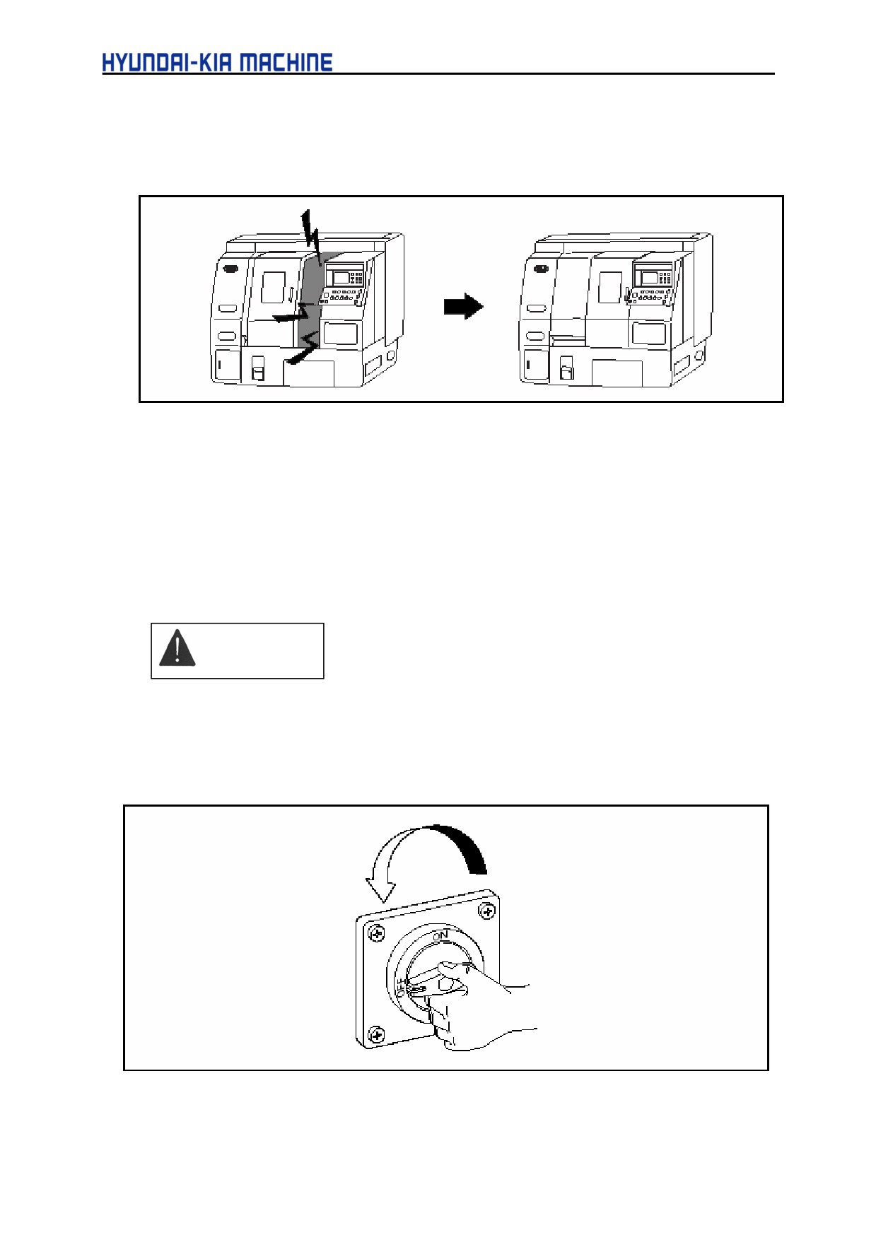
There are potentially dangerous situations inside of the machine such as rotating
workpiece, feeding tool post, dispersing coolant and hot chip. Always close the door of
machine while operating.
(10) Install the machine in a sufficiently bright, dry and arranged place free from any obstacles.
(11) Do not place device workpiece and other items either on the machine moving part or the
machine frame.
(12) Do not reconstruct the machine without our prior permission.
CAUTION
(1) Check the machine regularly according to this manual.
(2) Always close the door during the automatic operation.
(3) Immediately turn off the main power during a service interruption.
2-4
II. SAFETY
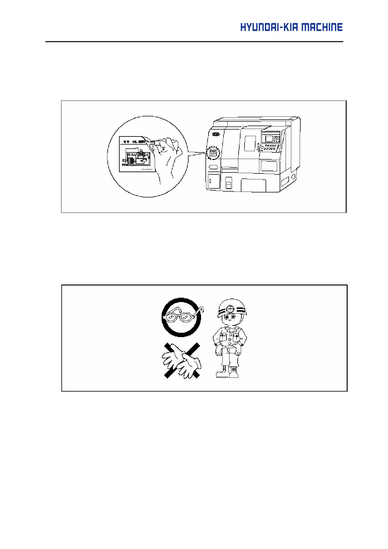
(4) Do not change the position of nameplate attached to the machine. If damaged, purchase it
with the item No. of Part List or one in the lower right of nameplate.
(5) Always wear protective glasses during working.
(6) Always wear safety shoes.
(7) Wear the safety cap and do not wear your uniforms loosely.
(8) Never operate the machine while wearing gloves.
(9) Keep the workbench near the machine enough to be strong and not to be slippery.
(10) Do not operate the machine while drinking of taking a medicine.
(11) Do not operate the machine when feeling a sick or sleepy.
(12) The max. noise of this machine is approximately 76 db. It is recommended to wear
earplugs.
2-5
3.
Notice When operating the Machine.
Before operating the machine, make sure the followings.
WARNING
(1) Always close the door of the Electric Control Panel to avoid damage due to water, chip or oil.
(2) It is dangerous to remove the chip attached or dropped to the tool with bare hands.
Therefore, stop the machine and wear gloves and then do a job using brush.
(3) Do not adjust the location of coolant nozzle while operating.
(4) Gradually increase the rpm of spindle to allow sufficient warming-up. Otherwise, it may result
in damage of the chuck cylinder (Refer to Repair and Preservation, step 2-9/5-1par. "A.
Warm up of spindle" ).
2-6
II. SAFETY
(5) Do not pull out or modify the
instruments or electric circuits
installed for a safety such as the
stroke limit dog of feed system, the
limit switch, the interlock limit switch,
and etc.
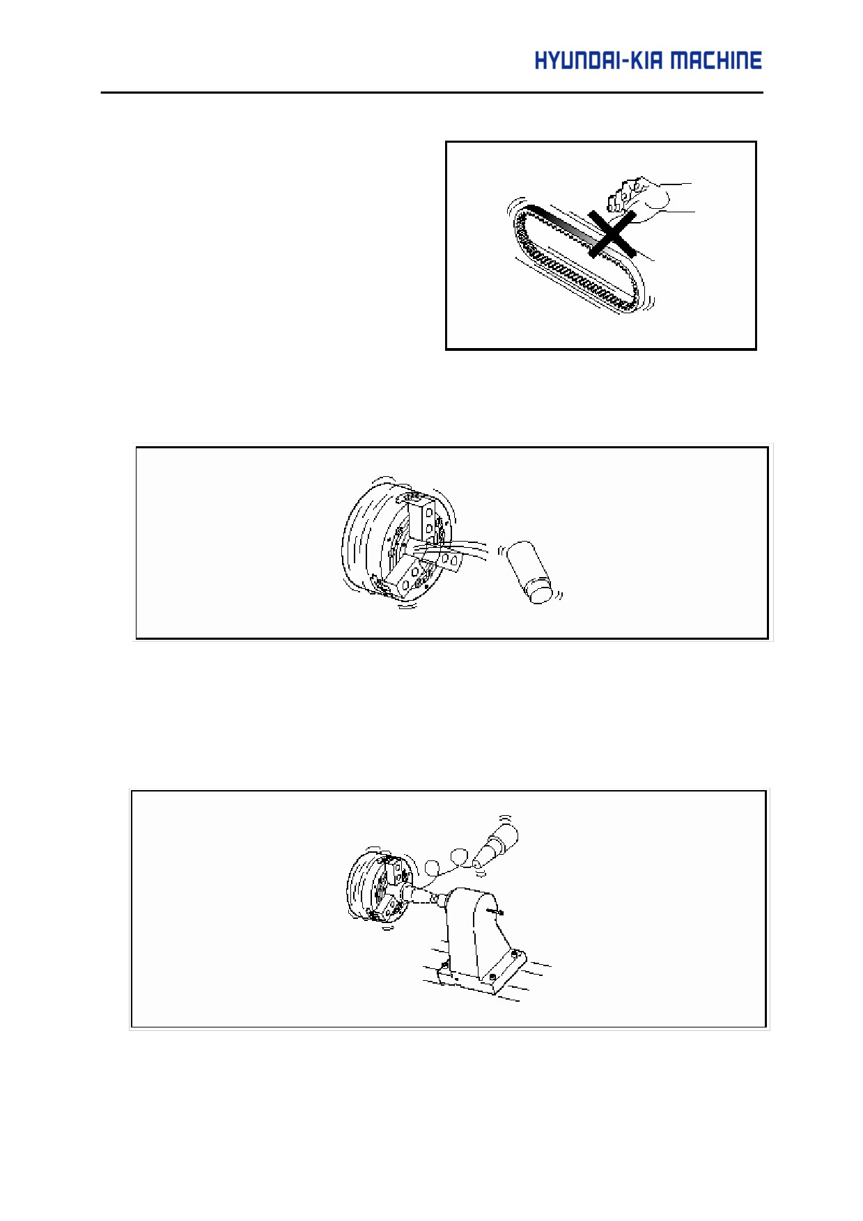
(6) Check the belt for tension. Make it
sure that your hands of fingers are not
hold between the belt and the pulley.
(7) Always clamp the workpiece or the tool exactly. For the cutting depth and feederate, begin
form the minimum level.
(8) When the machine rotated at a high speed, the clamping force of chuck will be decreased
rapidly. Be careful to set up the pressure of chuck and cylinder.
(9) When chucking and centering the center workpiece, take care of its weight, the hole of
center, configuration, and thrust of center. If centering and loading through a small hole, the
lead-edge of center may be broken and the workpiece sprung out.
2-7
(10) When self Boring of the soft jaw, pay attention to the location of self Boring Ring and
configuration of self Boring. After cutting the jaw, clamping the jaw correctly and check
the pressure of chuck is proper.
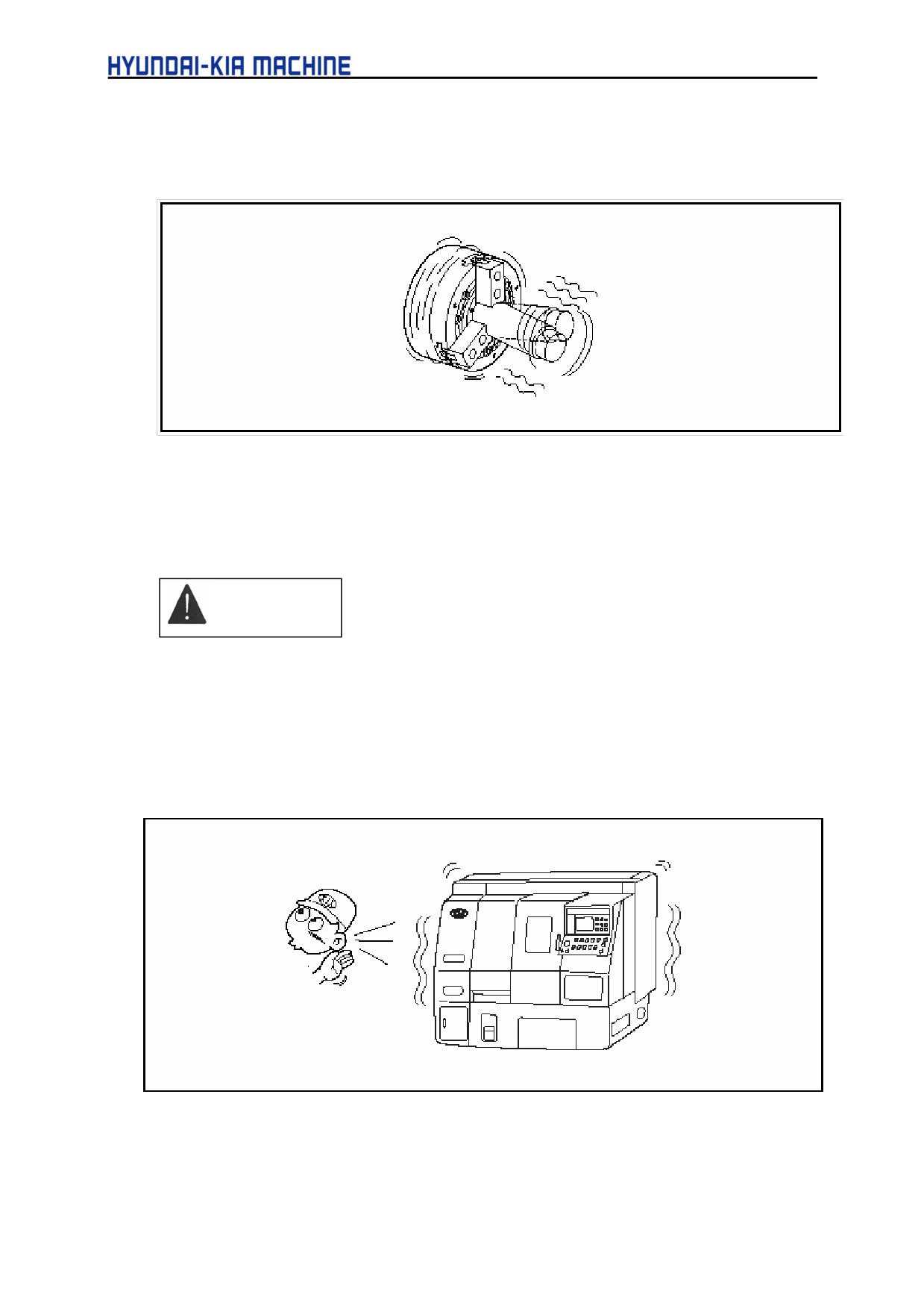
(11) If rotating the spindle when the center is not placed on the center of rotation and being
eccentric, it may cause the machine it self vibration and affect its working accuracy. Keep
its balance by attaching the balance.
CAUTION
(1) Do not touch kinds of switch with wet hands.
(2) While heavy cutting, a fire can happen due to a hot chip. Make it sure the chip not to be
accumulated.
(3) Check each bolt is clamped properly.
(4) Check there is a strange sound from the motor or anywhere else on working.
2-8
II. SAFETY
(5) Warm up the spindle and feed system prior to operating.
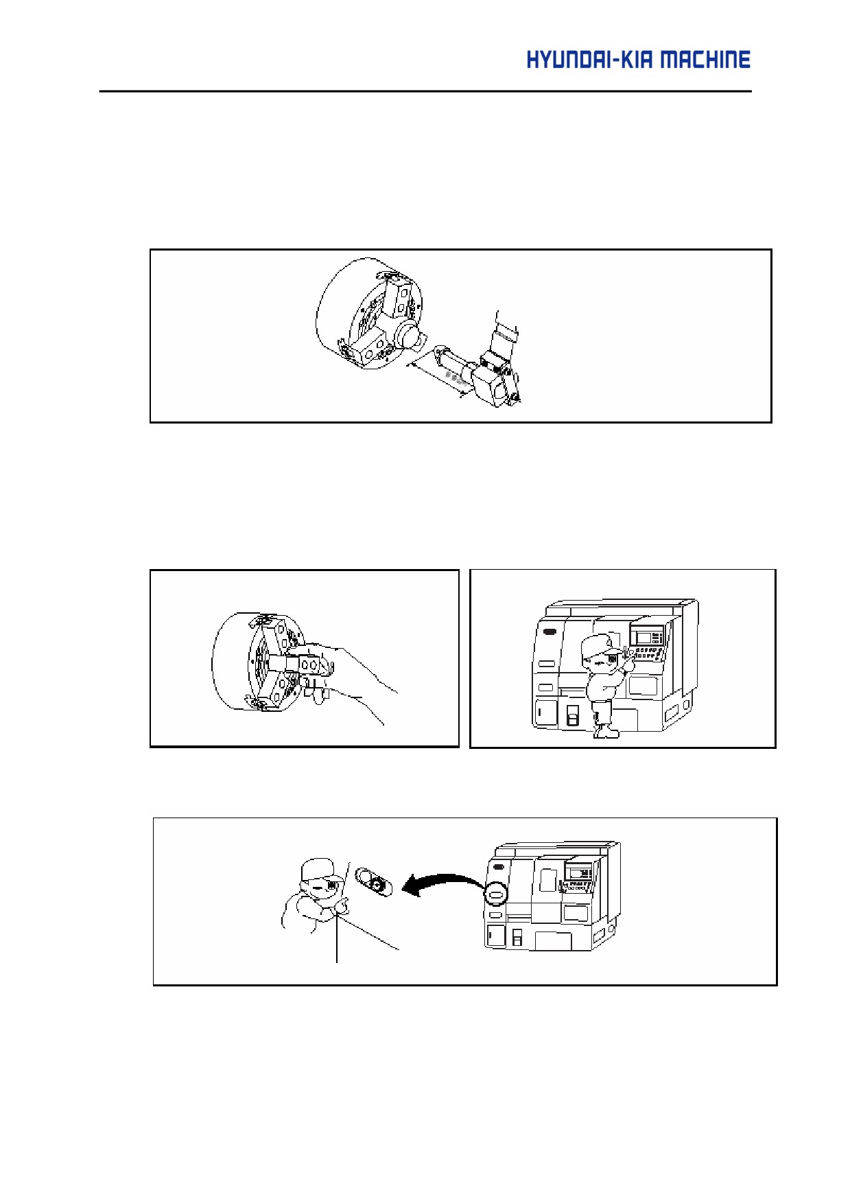
(6) When installing the tool, stop the feeding axis and the spindle.
(7) When installing the tool, pay special attention to the edge of tools. Install it not to be
protruded over the specified length.
(8) After installing the tool, first perform a test operation.
(9) When installing the workpiece on the standard chuck, make the outer circumference of
jaw positioned in the external diameter of chuck.
(10) Visually check the switch on the Operating Panel and then operate it correctly.
(11) Check the pressure gage indicates correctly.
(12) For the machine with special accessory, follow the specified instructions.
2-9
4.
Notice When Repairing and Checking
After reading this manual thoroughly, perform the maintenance.
DANGER
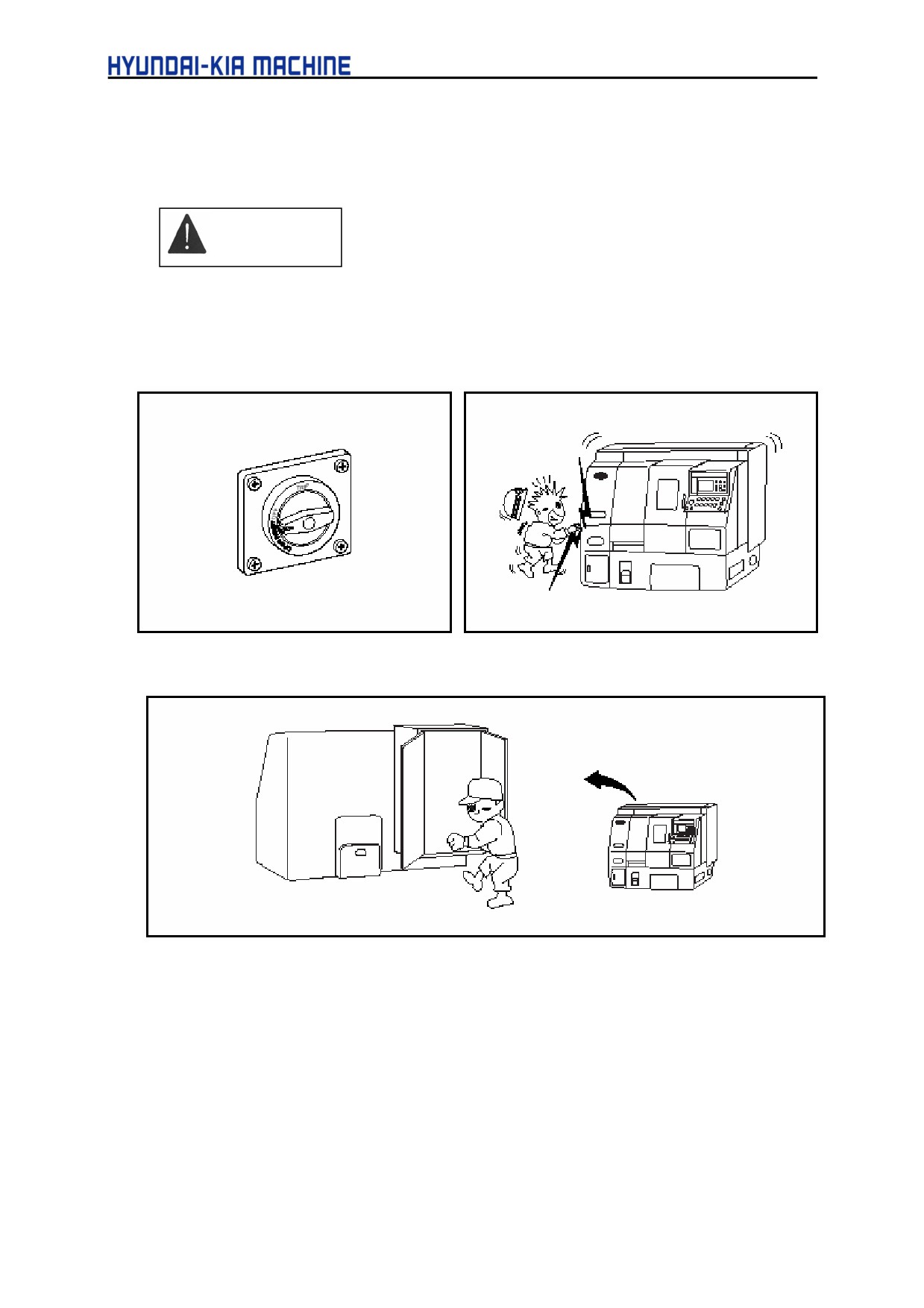
(1) Before repairing the machine, always ensure the main power is off.
(2) For a while even after the power off, always check there is residual current in the Electic
Control Panel and the Electric device and then perform the maintenance.
(3) Open the door of the Electric Control Panel only for repairing.
2-10
II. SAFETY
WARNUNG
(1) Only the qualified personnel can perform maintenance on the electric device.
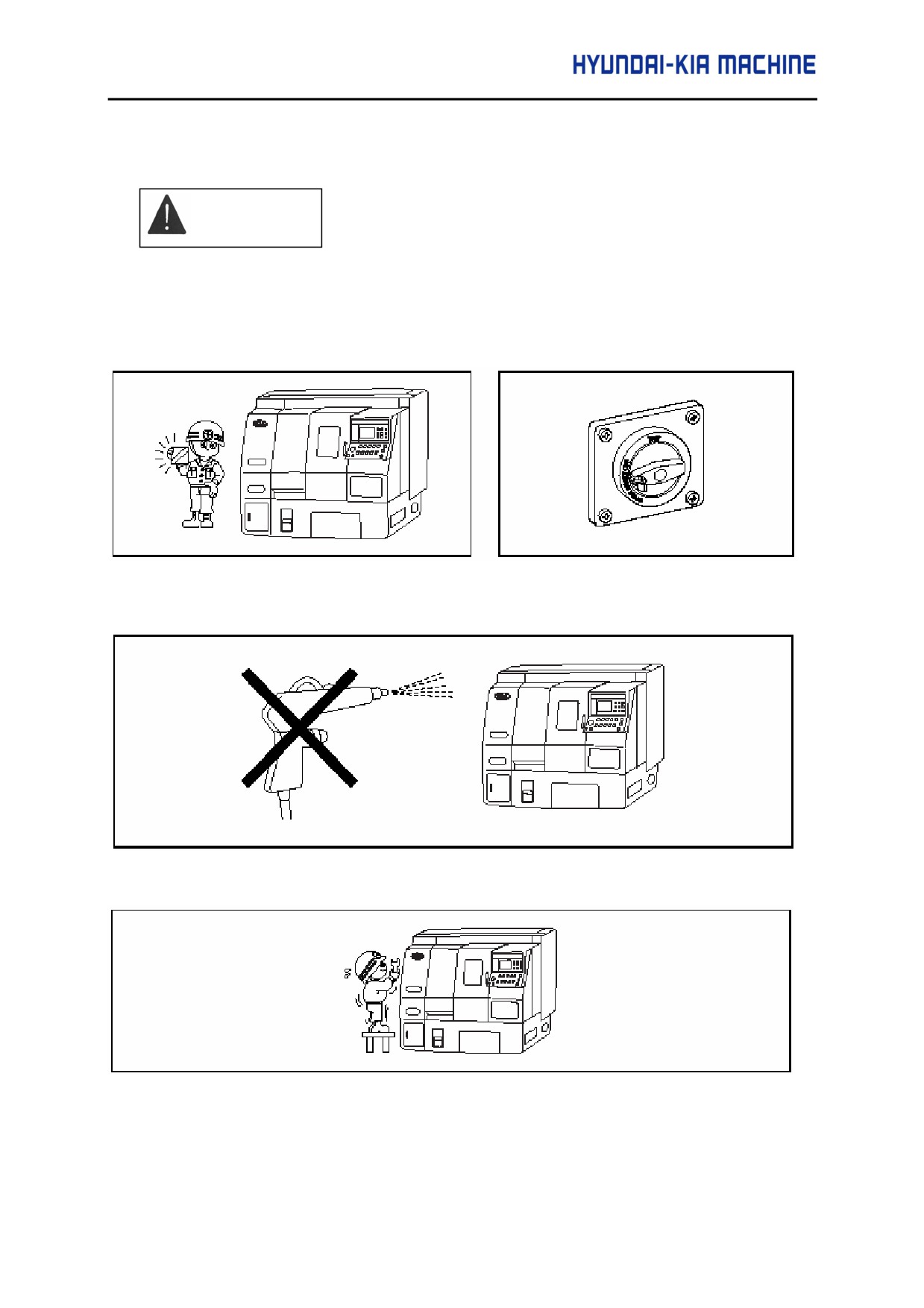
(2) When cleaning the machine, always stop its operation turn OFF and then lock the main
power.
(3) When repairing and cleaning the machine, do not use compressed air.
(4) When repairing at a high place, use a proper support or ladder and wear a safety helmet.
(5) Never operate the machine with the cover removed for repairing.
(6) While repairing or cleaning the machine, keep the floor free from water or oil.
2-11
WARNUNG
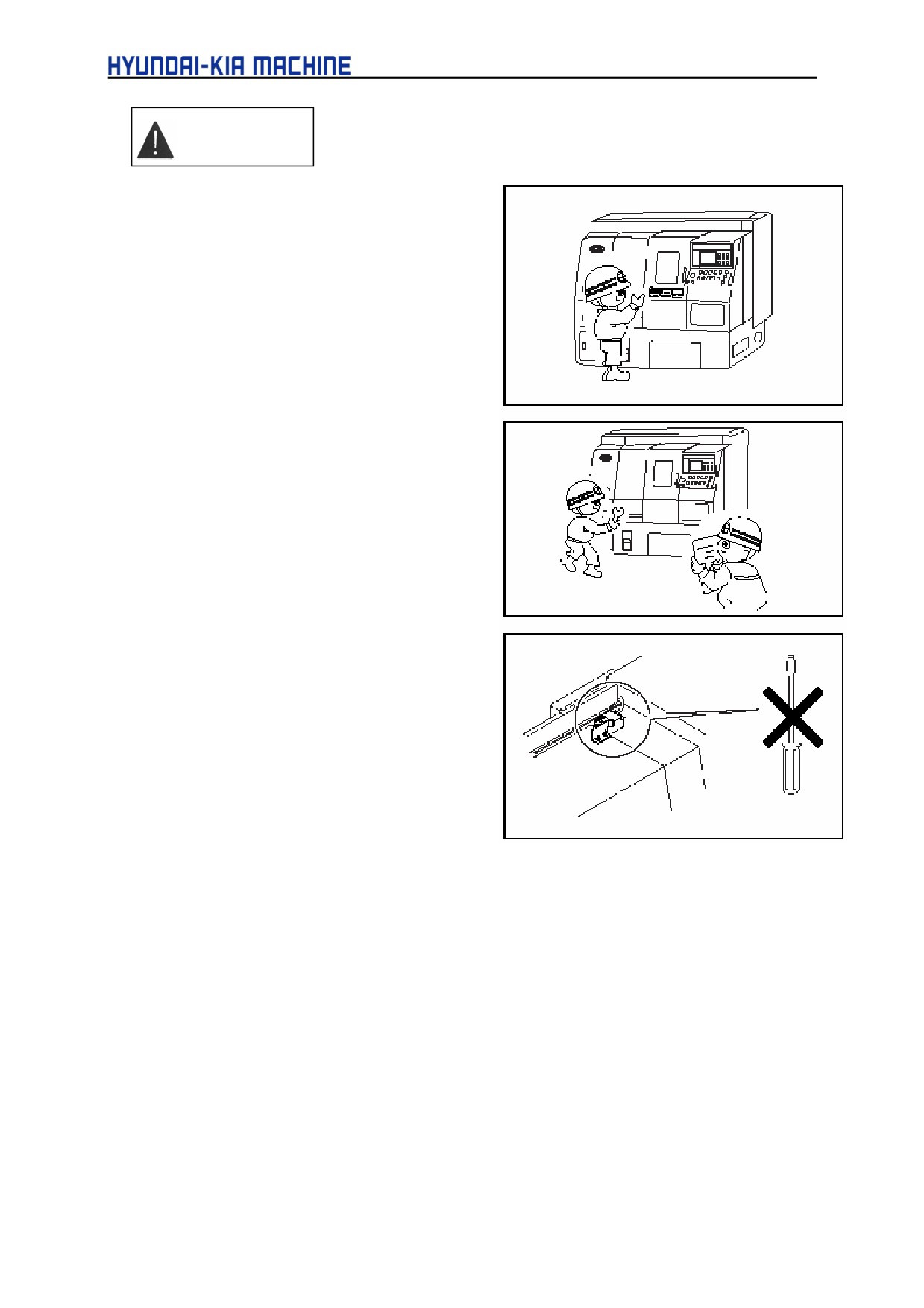
(1) Before repairing, completely read the
installation and Maintenance Manual.
(2) Keep enough parts in stock for repairing
and replacing.
(3) The person who responsible for
maintenance should obey the instructions
on the machine.
(4) Clean the machine after a completion of
daily work to make it easier to find out
anything wrong.
(5) When repairing, record the work.
(6) Do not attempt to remodel the device or
electric circuit such as the limit switches for
stoke limit, of interlock of the machine.
(7) Check each gage indicates its normal
value.
(8) Check the lubricating oil is supplied for
each wet moving part.
(9) Only use the specified hydraulic and
lubricating oils and greases in this manual.
(10) When cleaning the chip, always wear glove.
(11) Filling and changing oil should be performed periodically according to this manual.
(12) Apply each part with rust-proof oil after a completion of work, especially if using the
solvable coolant.
(13) Use the specified spanner or wrench when adjusting and repairing the machine.
2-12
II. SAFETY
5.
Notice on the Electric and NC Devices
DANGER
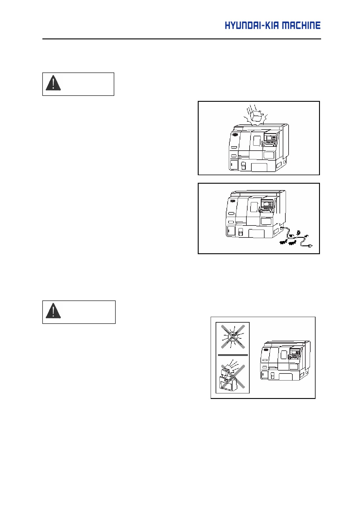
(1) Do not give a shock on the NC device and
the Electric Control Panel, etc.
(2) In case of the power cable, use it with the
same thickness provided in this manual,
and do not use longer cable than needed.
When the power cable has to be passed
the floor, be sure to prevent it from being
damaged by chips.
(3) In case of test operation, check the
parameter of NC device is set properly with
our instructor attended. Also, do not
change any parameters except one for
backlash.
WARNING
(1) The Electric Control Panel is sealed to prevent
the ambient air from entering. Do not open the
door of Control Panel for long while applying the
power. Direct ray of sun or flash of camera may
result in damage of the part.
2-13
(2) The instruments specified by our company should be used in the Electric Control Panel.
Especially use the specified fuse and never use that of great capacity or a copper wire.
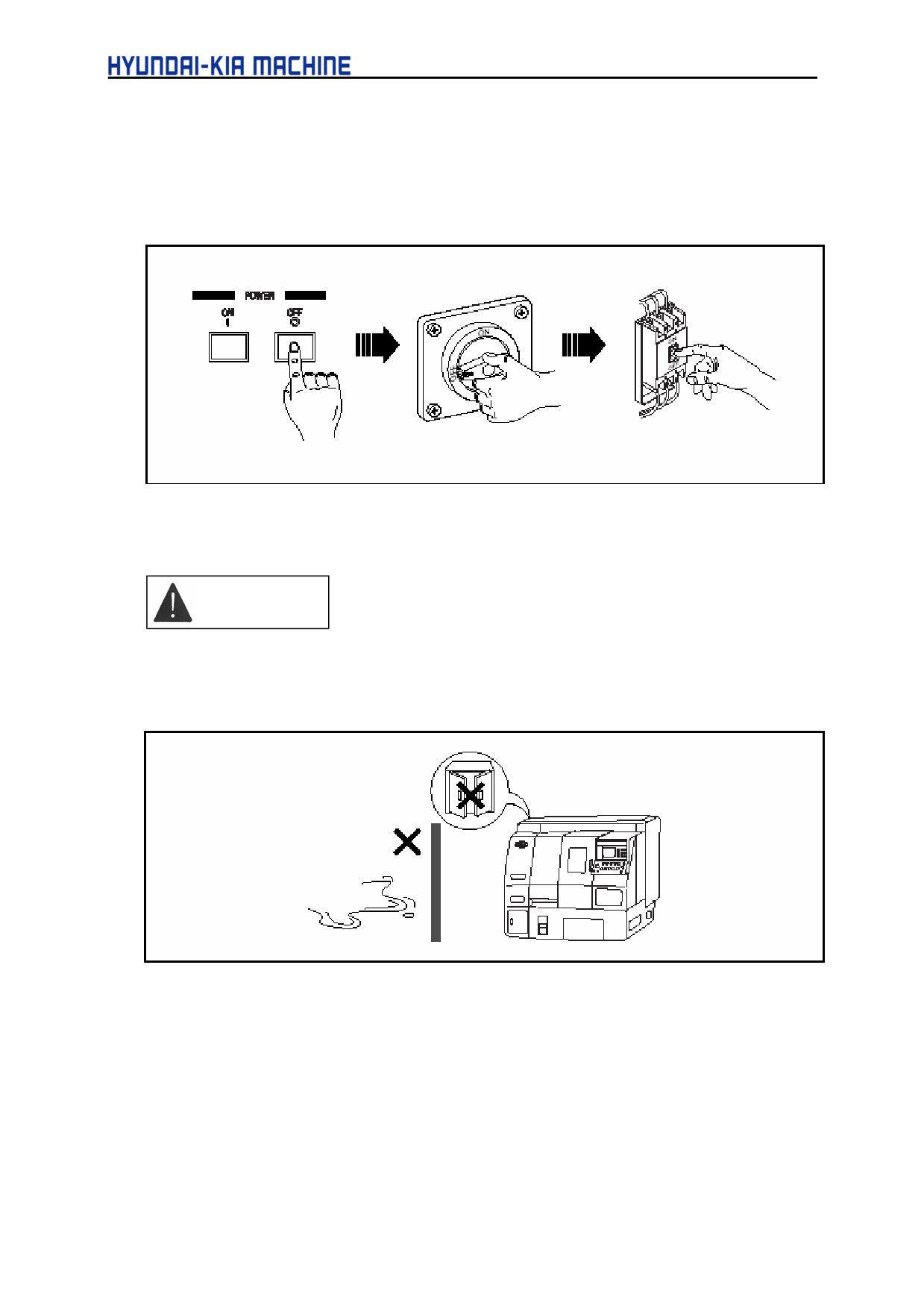
(3) When repairing the electric instrument, switch OFF the power of the Operating Panel. Also
switch OFF the Electric Control Panel and then the Power Supply at factory.
(4) Do not change a current setting of the overload relay in the Electric Control Panel and any
settings of various volumes.
CAUTION
(1) Do not open the door of the Electric Control Panel or the Operating Panel, if possible. The
penetration of foreign material or humidity may result in misoperation.
(2) Special care should be taken in handling the electric instrument of the body.
(3) Clean the fan and filter in the Electric Control Panel regularly.
(4) Check the no of program on the screen of the Operating Panel.
2-14
II. SAFETY
6.
Safety Device
6-1. Name Plates
2-15
6-2. Safety Device
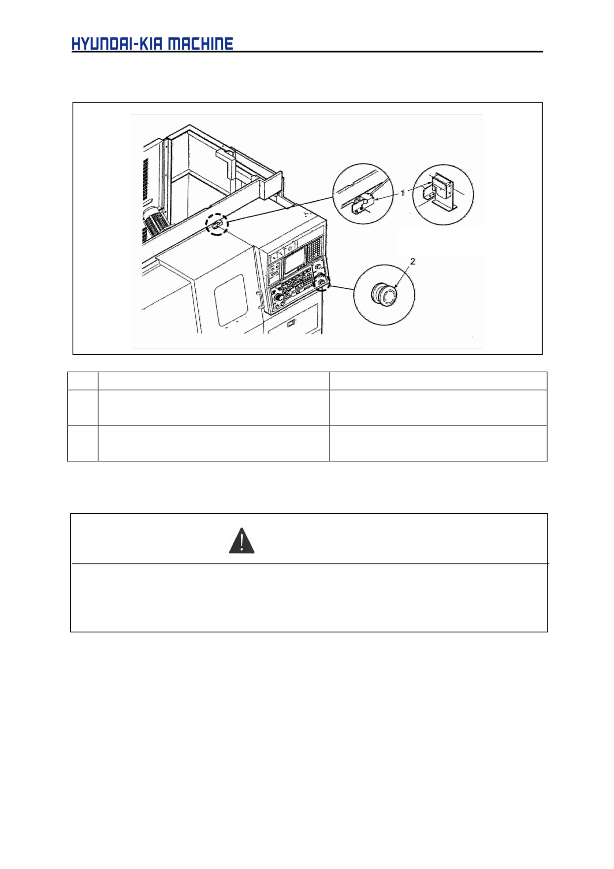
* Applicable only to
the C.E.
No.
Name
Function
1
Door Lock System
If the door opened while operating the
machine, it may be in Emergency Stop sate.
2
Emergency Stop Switch
If Pressing this switch, all operating parts
except hydraulic ones will be stopped.
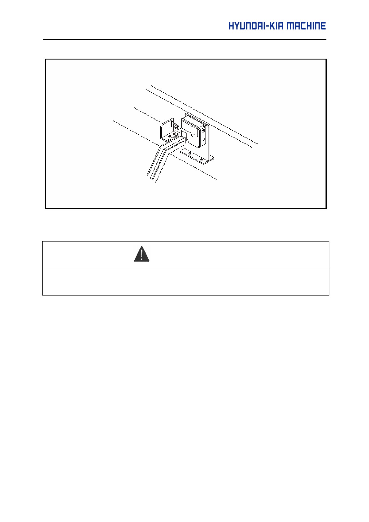
6-2-1. Door Lock System (Applicable only to the C.E)
WARNING
Set the "LOCK / UNLOCK" switch of door lock system to "LOCK" .
If setting it to "UNLOCK" , it may allow the door to be opened while operating and cause
serious risks.
2-16
II. SAFETY
If a power failure occurred while operating, turn the lock switch to "UNLOCK" to open door
WARNING
We are not responsible for the accident due to unauthorized modifications of Door Lock
System.
2-17
III
SPECIFICATION
III SPECIFICATION
1.
Introduction
3-1
1-1. Head Stock
3-1
1-2. Tool Post
3-1
1-3. Tail Stock
3-1
2.
Specification
3-2
2-1. Spindle Output and Torque Diagram
3-3
3.
NC Device Specification (FANUC Oi-TB)
3-4
3-1. G Function
3-7
3-2. M Function (Auxiliary)
3-9
4.
Head Stock
3-12
4-1. SUPER KIATURN 100
3-12
4-2. SUPER KIATURN 200
3-13
4-3. Major dimension of Head Stock
3-14
5.
Chuck and Rotary Cylinder
3-15
5-1. Hollow Chuck Major Dimension
3-15
5-2. SUPER KIATURN 100 Hollow Chuck
3-16
5-2-1. Connecting Parts for Rotary Cylinder
3-16
5-2-2. Major Dimensions
3-17
5-3. SUPER KIATURN 200 Hollow Chuck
3-17
5-3-1. Connecting Parts for Rotary Cylinder
3-17
5-3-2. Major Dimensions
3-18
6.
Tool Post
3-19
6-1. Turret
3-19
6-2. SUPER KIATURN 100
3-20
6-3. SUPER KIATURN 200
3-21
III. SPECIFICATION
1.
Introduction
1-1. Head Stock
Ensures the wide-range change in speed by the AC spindle motor as follows:
For SUPER KIATURN 100, between 30 and 6.000 rpm and for SUPER KIATURN 200, between
30 and 4.000 rpm.
Besides, it enables the constant surface speed control by the AC spindle motor.
1-2. Tool Post
Ensures more rapid and accurate indexing work (0,12 sec/surface) by the servo motor and the
3-pice coupling.
1-3. Tail Stock (Option)
Install the taper of MT No. 4 sold as a commercial live center.
The tail stock is set to random position by controlling the key above the support. Also, the thrust
can be adjusted between 50 and 450 Kgf (500N and 4.500N) according to the hydraulic
adjustment.
3-1

2.
Specification
Table 3-1
Specification
Item
Unit
SUPER KIATURN
SUPER KIATURN 200
100
Swing over Bed
mm (in)
φ550 (21.6)
Max. machine dia.
mm (in)
φ350 (13.8)
Chuck size
mm (in)
φ 165 (6)
φ 210 (8)
Capacity
Swing over cross
mm (in)
φ350 (13.8)
Max. turning length
mm (in)
300 (11.81)
Bar capacity
mm (in)
φ45 (1.77)
φ65 (2.6)
Speed
rpm
6,000
4,000
Speed variation
randomly
Spindle
Spindle dia (Bearing)
mm(in)
φ90 (3.54)
φ110 (4.3)
Spindle nose
A2-5
A2-6
Bearing arrangement
ball bearing
Floor-Center height
mm(in)
1,010 (39.76)
Turret type
sec
12-angle variable arrangement
Tool Post
Tool size
25/Ø32(
1Ø11/4)
25/Ø40(
1Ø11/2)
Indexing time (1step/full)
each
0.12/0.24
Mechanism
sec
Servo
Guide type
LM-Guide
Travel
X-axis
mm(in)
210 (8.2)
Travels
Z-axis
mm(in)
330 (12.99)
Traverse
X-axis
m/min(in/min)
36 (1,417)
Z-axis
m/min(in/min)
36 (1,417)
Tail stock taper
MT4
Tail stock dia.
mm (in)
φ56 (2.2)
Tail Stock
Tail stock travel
mm (in)
80 (3.15)
(Option)
Tail stock thrust
kgf (N)
450 (17.72)
Feeding method
manual
Spindle
kW (Hp)
5.5/7.5 (7.4/10)
7.5/11 (10/55)
Feed drives
X-axis
kW (Hp)
1.6
(2.2)
Motor
Z-axis
kW (Hp)
1.6
(2.2)
Coolant
kW (Hp)
0.18
(0.24)
Power Capacity
KVA
11.4
14.1
External size (L x W x H)
mm (in)
1,943x1,650x1,820 (76.5x64.96x71.65)
Others
Machine weight
kg (N)
3,800 (38,000)
3,900 (39,000)
controller
FANUC 0i-TB
*
The standard CHUCK & CYL should be attached, otherwise, it might cause serious injury to
human body. You should use the approved one by our company.
3-2