Hyundai SKT 100/200 CNC TURNING CENTER. INSTALLATION MAINTENANCE MANUAL (VERSION No.: VOL1.0) - page 6
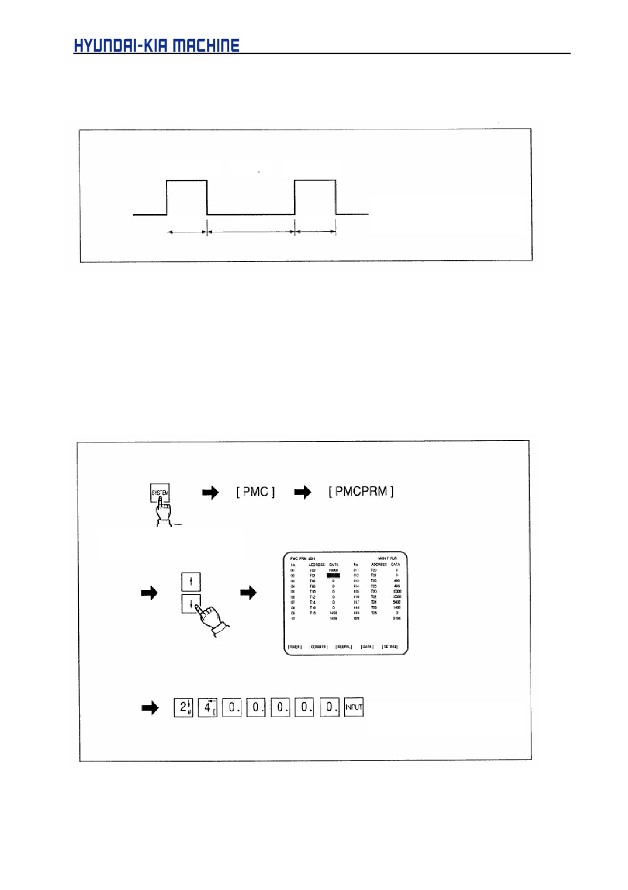
3-5-3. Discharge of Lubricating Oil
1) Discharging period
Operation
stop
Operation
Flow
: 100cc/min(0.02gal/min)
10sec
20min.
10sec
Pressure: 8 kgf/cm2 (0.8 MPa)
a. Discharging time is set to 10 seconds.
(TO No. TOO = 10000)
b. Discharging period is set to once a 20 min.
(T2 No. T02 = 1200000)
2) Adjustment of discharging period
To set the stop time to 40 min., perform as follows
Press "SYSTEM" kev and
select the parameter screen
, the setting time is changed
to 40 minutes.
5-70
V. REPAIR AND PRESERVATION
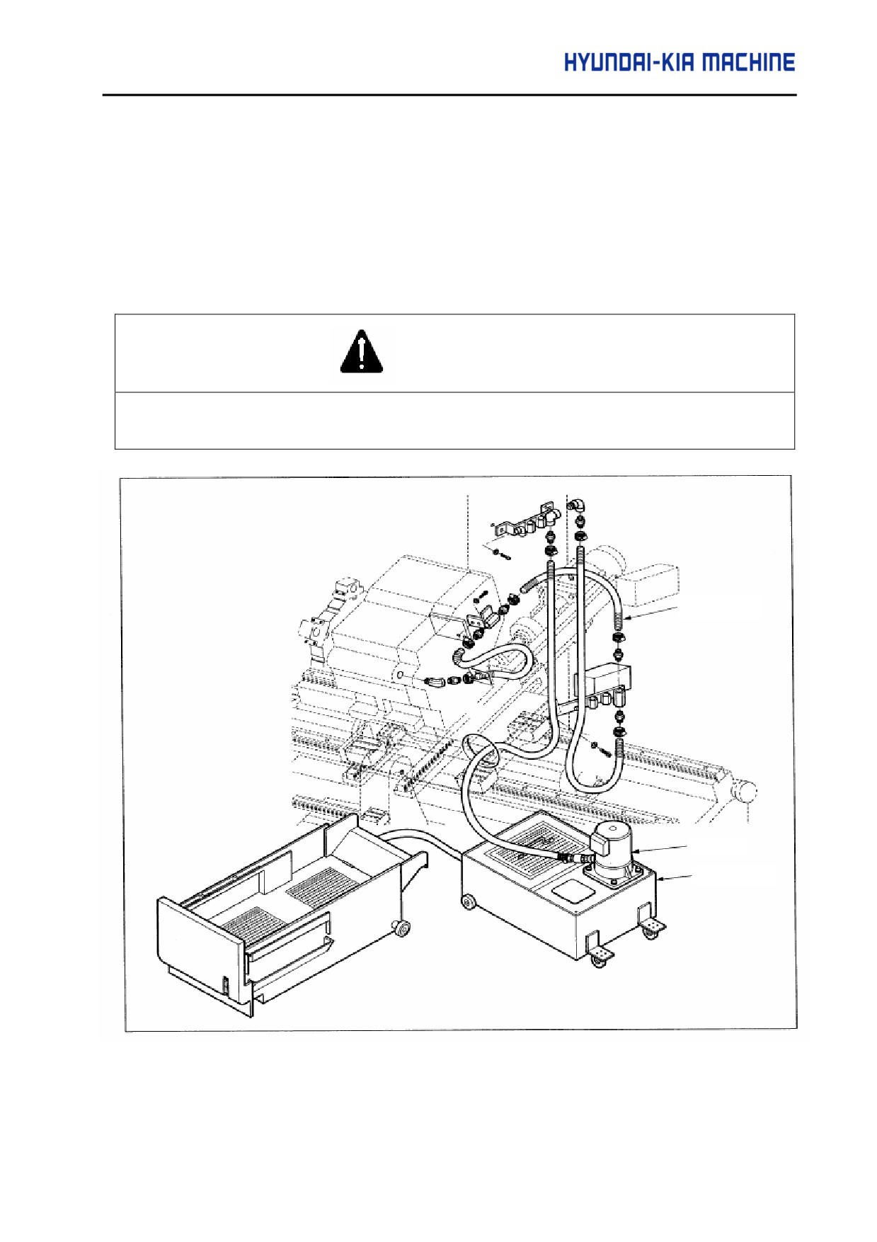
3-6. Coolant
3-6-1. Coolant Unit Construction
Coolant is pumped by the pump in coolant tank, injected through the nozzle and used to cool and
lubricate the workpiece.
CAUTION
Coolant can be divided to solubility or unsolubility in water, but it is recommended to use
water-soluble coolant because in case of being unsoluable, it may cause major parts to be rusted.
Hose
Pump
Tank
Fig. 5-60 Coolant and Construction
5-71
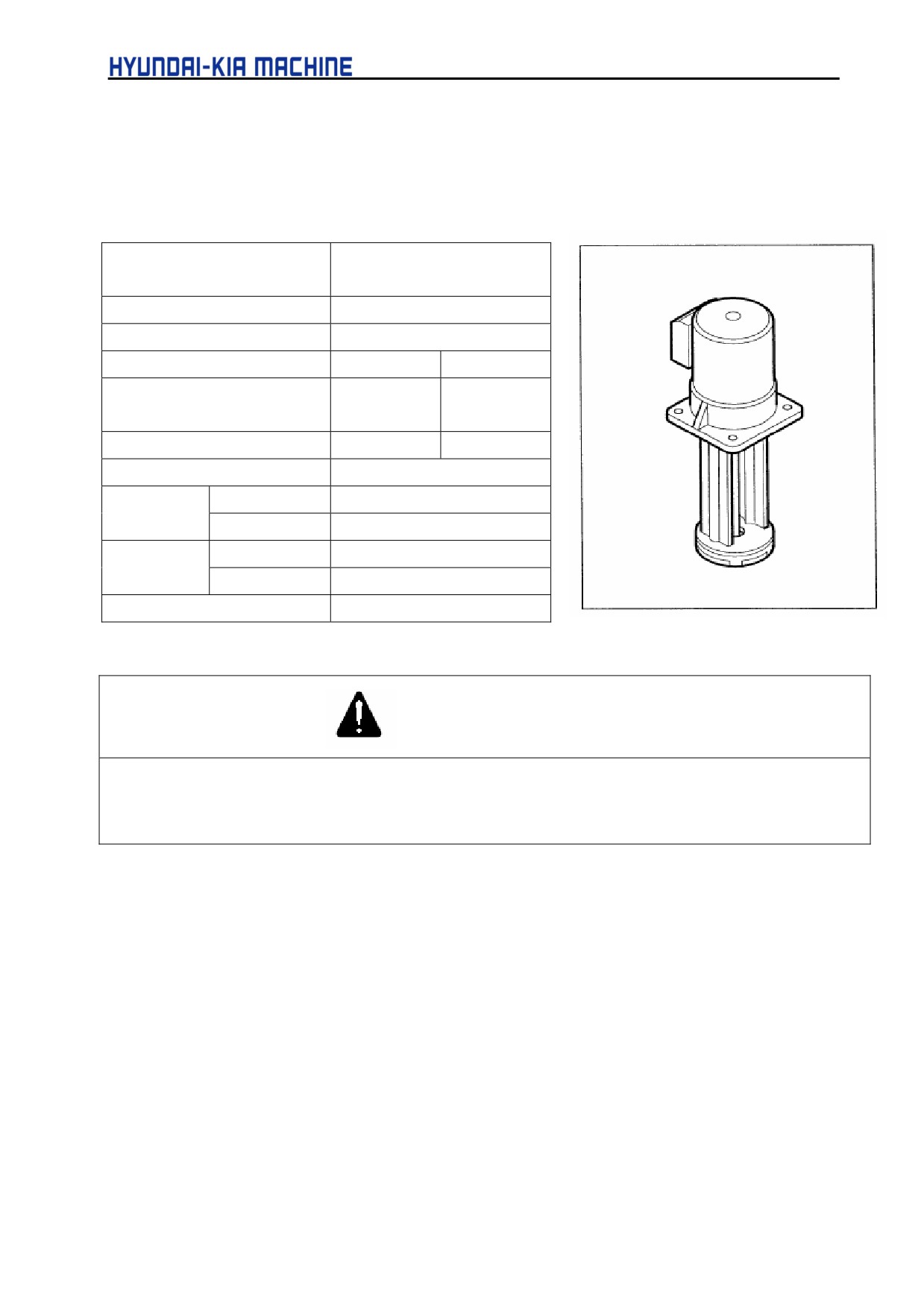
3-6-2. Specification and Cleaning
1) Specification
Table 5-6. Specification Table
Type
Flooding style
ACP-180F
Power (kW)
0.18(0.24HP)
Polarity
3 Ø • 2P
Voltage (V)
220
220/380
Permissible Maximum
0.58
1.0
Current (A)
Frequency (Hz)
50
60
Ambient Temperature (°C)
-15-40
Discharge
50 Hz
75
(l/min)
60 Hz
90
Overall lift
50 Hz
3
(m)
60 Hz
3
Available Density Limit (R")
1200/600
Fig. 5-61 Pump
CAUTION
The discharging amount of the above table is the flow on the discharge port of pump when the back pressure is
set to "0". The discharging amount from the actual nozzle is different depending on the size of nozzle, pipe
resistance, the height of nozzle and pump, and density of coolant.
2) Cleaning
Used tools:
- wrench (5, 6, 7mm), + driver, clothes, coolant collecting box
a. Stop discharging of coolant
b. Open the drain plug of tank and allow the residual oil to drain using drain hole.
c. Remove the cover plate above the tank.
d. Disconnect the filter of sub tank.
e. Clean the inside of the tank, cover plate and filter.
5-72
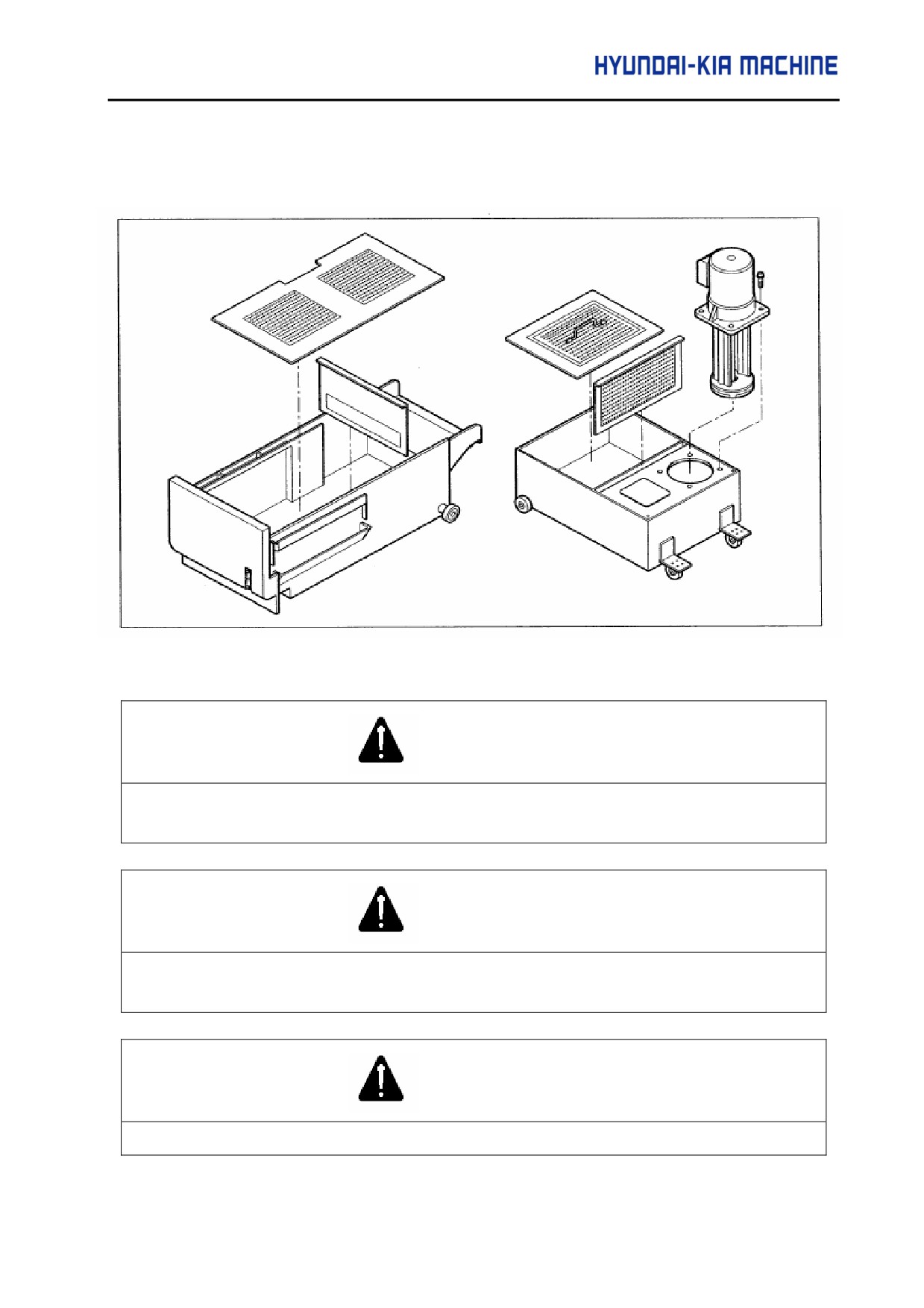
V. REPAIR AND PRESERVATION
f.
Fill coolant (185 L) into tank
g. Assemble it in the reverse order of disassembly.
Fig. 5-62
Coolant Tank Disassembly Diagram
CAUTION
When cleaning the coolant tank, remove oil dropped on the floor. Otherwise, it may cause personal
injury.
CAUTION
When filling coolant, you should use the oil recommended by KIA. Otherwise, it can cause machine
failure.
CAUTION
Remove the cover plate above the tank and sludge from the chip box regularly.
5-73
3-6-3. Check and Repair
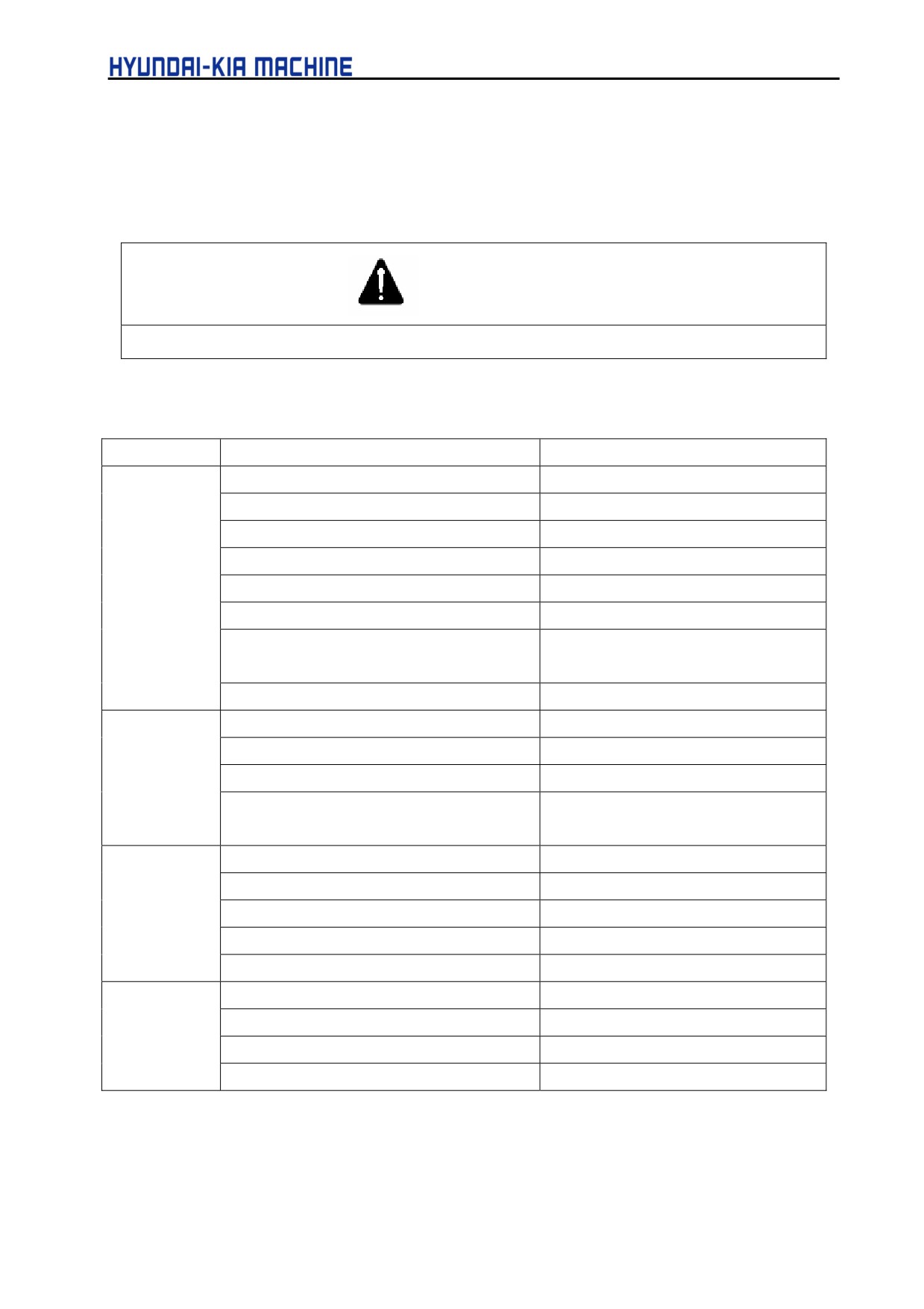
If there are vibration, noise, and abnormal discharging in coolant pump during daily operation,
immediately stop discharging of coolant and repair as a reference with the following table.
CAUTION
Before checking and repairing coolant, turn OFF the power. Otherwise, it may cause personal injury.
Table 5-7. Checking and Repairing
Fault
Possible Cause
Remedy
Motor will not
Disconnected
Repair or change
rotate
Trip thermal circuit break
After, analysizing the cause, on
Poor contact of switch
Inspect of contacts
Low voltage
Contact the Electric Power Co.
Faulty motor
Exchange
Foreign matters in the fan
Disassemble and Repair
Wet moving part
(damaged Liner
Ring
Disassemble and Repair
Bearing)
Rusted shaft
Disassemble and Repair
Motor rotates
Low rotation speed
Check the rotation system
but coolant will
Clogged pipe line
Check and clean pipe
not pump.
Pump improperly flooded in coolant
Fill coolant and clean tank
Fan not being flooded in coolant
Open the air plug one time and allow
the ambient air to enter
Coolant
Clogged fan and case
Disassemble and Repair
pumps but
Worn fan
After diassembling, repair or change
can't obtain
Water leakage in discharging pipe
Check and repair
the specified
Low rpm
Inspect or review the rotation system
amount.
Clogged pipe
Check and clean the pipe
Overload of
High gravity and viscosity
Check coolant
motor
Contacted rotation part
Exchange
Excess discharge
Exchange
Low voltage
Contact Electric Co.
5-74
V. REPAIR AND PRESERVATION
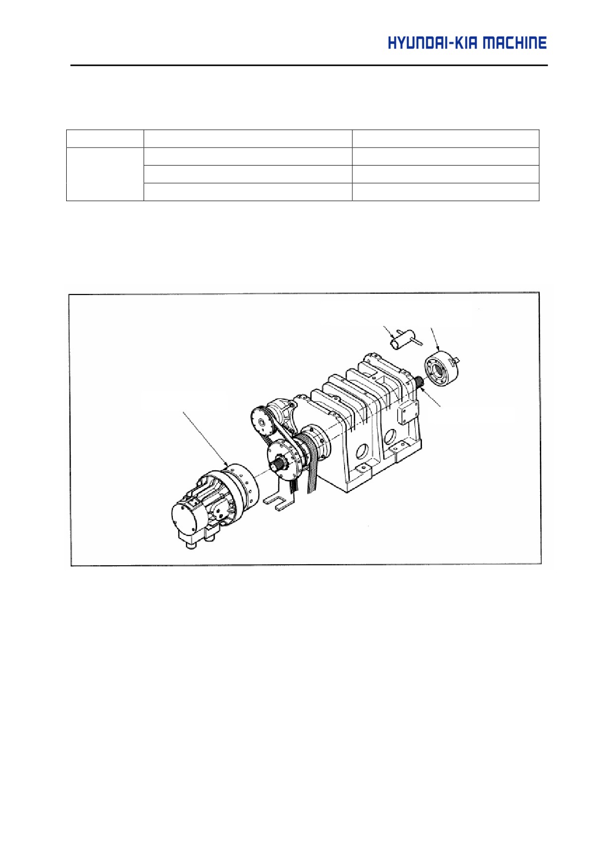
Table 5-7. Checking and Repairing (cont.)
Fault
Possible Cause
Remedy
Vibration or
Clogged and unbalanced fan
Disassemble and check
noise in pump.
Damaged bearing or body
Change
Cavitation
Contact the manufacturer (Maker)
3-7.
Chuck and Cylinder
3-7-1. Chuck and Cylinder Constructions
Connecting
Hydraulic
Tube Handle
Cylinder Adaptor
Tube
Fig. 5-63
Chuck and Cylinder Construction
Used Tools: wrench (8, 10 mm), spanner (17 mm)
5-75
3-7-2. Adjustment
1) Adjusting Sequence
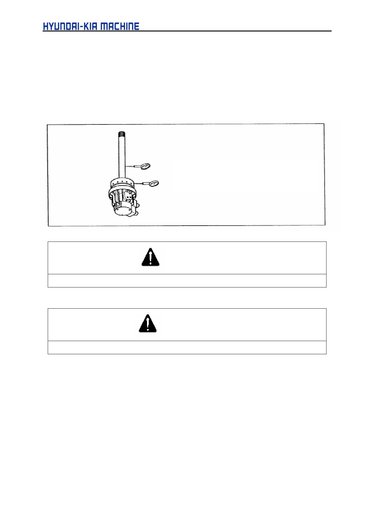
a. Secure the rotation cylinder to cylinder adaptor using bolts and connecting tube to
cylinder using the connecting nut.
b. When assembling them, adjust the trembling.
Connecting tube less than 0.1 mm
Connecting adaptor less than 0.01 mm
CAUTION
If assembling the cylinder with connecting tube, do it with pulled out.
WARNING
Turn OFF the power. Otherwise, it may cause personal injury.
c. Put the assembled cylinder bundle into the hole of spindle.
d. Fit the cylinder adaptor to the spindle flange using bolts, (trembling less 0,01 mm)
e. Fit the chuck to the connecting tube and assemble it to spindle.
f.
Adjust the trembling of chuck to be less than 0,02 mm.
g. Engage with connecting tube handle until the stroke of jaw being within specified value.
h. Connect the hydraulic hose.
i.
Check the chuck is opened or closed properly.
j.
Raise the pressure of chuck up to the permissible pressure.
5-76
V. REPAIR AND PRESERVATION
k. Check each part for leakage or abnormal.
l.
Turn the spindle with the speed of 500 rpm and check for its vibration, (about 5 minutes)
m. Slowly raise the rpm of spindle and check for its vibration.
n. If the vibration being high, stop the spindle.
o. Reassemble the cylinder.
3-7-3.
Specification
1)
Seizing power
Seizing power is different depending on the fueled state, used grease, height of soft jaw. When
engaging the machine in chuck and operating within the limit of maximum permissible
pressure, the actual seizing power decreases as the speed of spindle increases because of a
centrifugal power. These relationships between the speed of spindle, power and seizing power
are shown in the following graph. Use the following jaw to obtain the seizing power of chuck.
a. Use the standard soft jaw.
b. Refill the recommended oil in this manual.
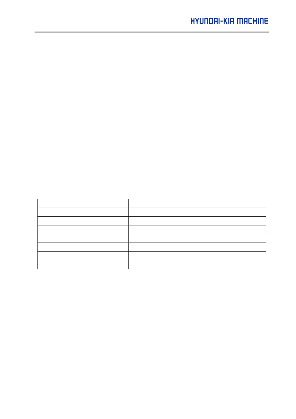
c. Secure the soft jaw engaging bolt in the specified torque.
Bolt size
Specified torque
M6
130 kgf • cm
(13 N • m)
M8
390 kgf • cm
(39 N • m)
M10
640 kgf • cm
(64 N • m)
M12
1090 kgf • cm (109 N • m)
M14
1740 kgf • cm (174 N • m)
M16
2550 kgf • cm (255 N • m)
M20
4100 kgf • cm (410 N • m)
d. The thrust of cylinder is the permissible maximum one.
5-77
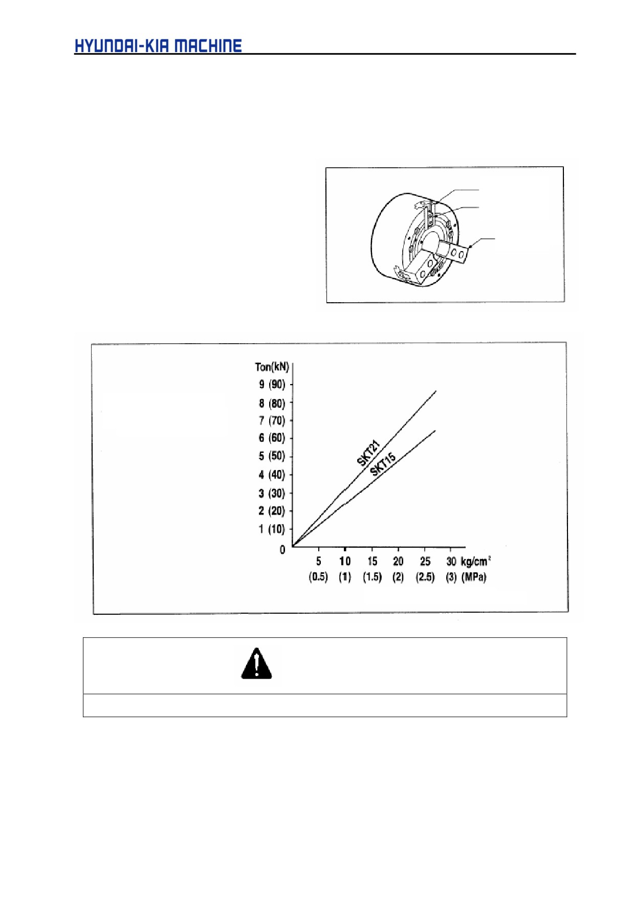
2) Permissible maximum rpm of Spindle
The permissible maximum rpm of Spindle is maintained to more than 1/3 of the rated power in
the chuck seizing power when the outside end has been placed inside of the circumference in
the Chuck body. This time the maximum rpm of spindle depends on the maximum rpm of
chuck.
Master Jaw
a. Use the standard soft jaw.
T-nut
b. Place the master jaw in the center
of stroke.
Soft Jaw
c. Attach the soft jaw inside of the
circumference in chuck.
Chuck Seizing Power
(Total of 3 jaws
Cylinder Pressure (kg/cm2)
WARNING
When cutting heavily in a rapid speed, make sure the workpiece not to be sprang out.
5-78
V. REPAIR AND PRESERVATION
4) Attachment of Soft Jaw
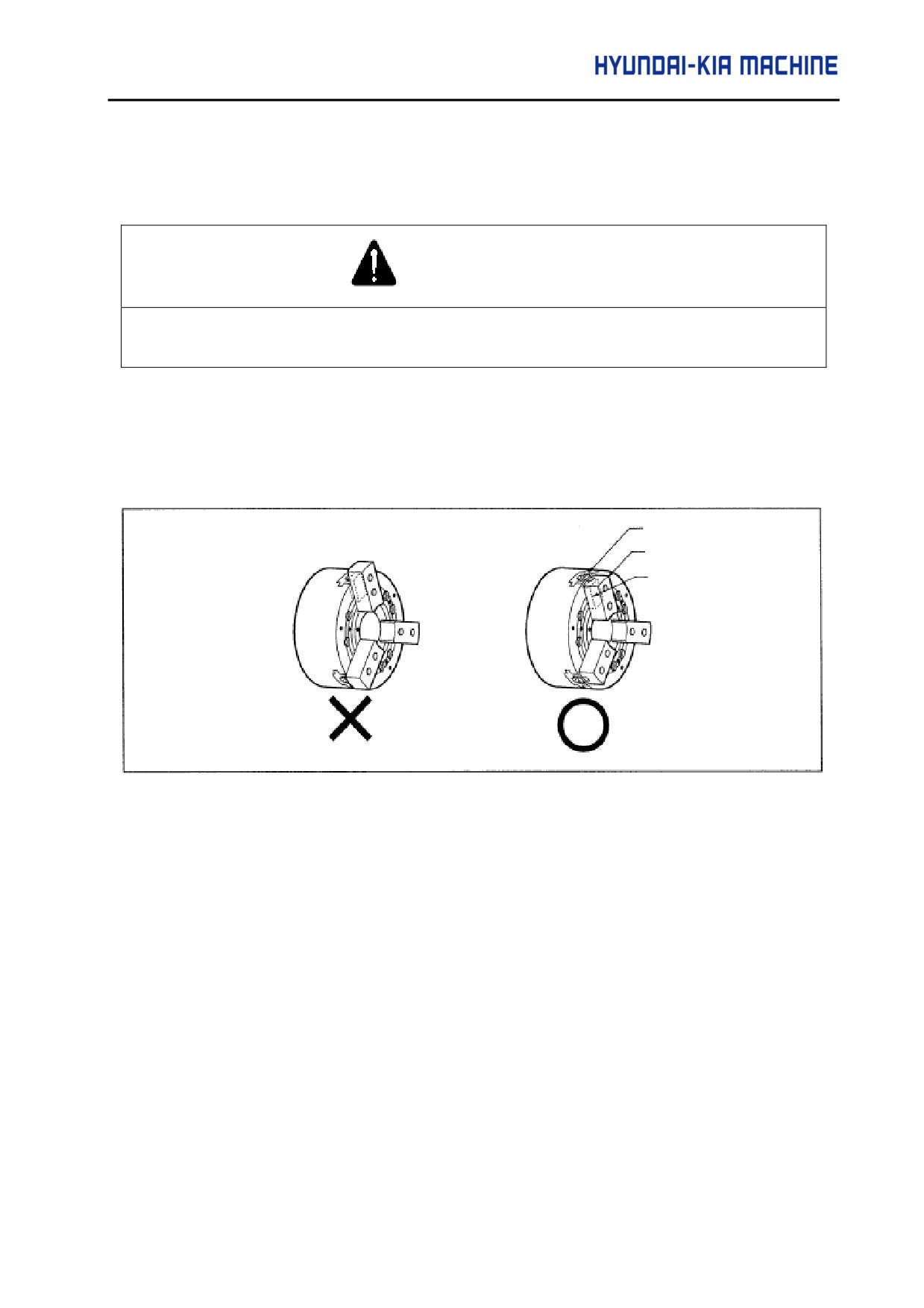
a. Use the jaw nut for attaching the soft jaw of chuck within the range of soft jaw.
DANGER
If the jaw nut has been protruded out of the circumference, only one bolt will be engaged with jaw and
may cause personal injury.
Used tools: wrench (8 mm SKT100), wrench (10 mm, SKT200)
b. Install the jaw nut inside of the circumference in Chuck as shown in the following.
Master Jaw
Soft jaw
Jaw Nut
5-79
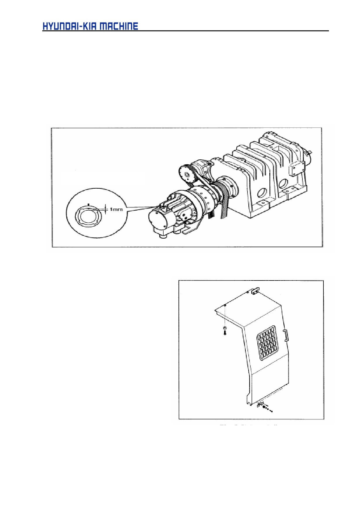
5) Adjustment of proximity switch for checking the operation of cylinder
The proximity switch for confirming clamp/unclamp of the workpiece is attached inside of the
coolant collector in cylinder.
Used tool: spanner (19 mm)
a. Engage the screw of proximity switch and the adjusting plate so the distances between
proximity switch and guide flange might be 1 mm.
b. Check the proximity switch for operation.
Proximity Switch
Fig. 5-64 Proximity Switch for Checking Operation of Cylinder
3-8.
Cover
3-8-1. Door Roller
Used tool: spanner (13, 17 mm)
1) Disconnect the door and change
the upper and lower rollers.
2) If reassembling the door, check
the door for flat state and
operation and adjust the lower
roller.
Fig. 5-65 Door Safety Glass
5-80
V. REPAIR AND PRESERVATION
3-8-2. Door Safety Glass
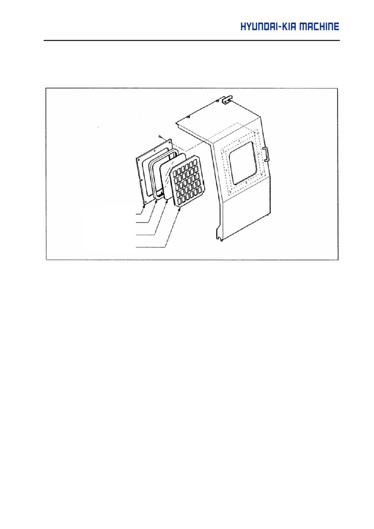
Plate
Packing
Glass
Guard
Fig. 5-66 Door Safety Glass
Used Tool: + driver, sealing agent
If the door safety glass has been broken due to the tool tip or workpiece while operating the
machine, exchange as follows:
1) Disconnect the door
2) Disconnect the place using + driver and remove the glass.
3) Remove a piece of glass thoroughly.
4) Apply the boundary of guide with sealing agents and insert the packing into glass.
5) Put a glass on the guide and engage the plate.
5-81
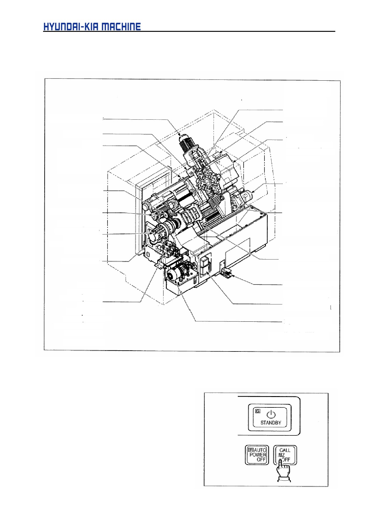
3-9
Electricity
3-9-1. Electric Device Layout
X-axis
Torque L/S SQ6
Origin L/S SQ5
+OT L/S SQ3
-OT L/S SQ4
X-axis Servo Motor
Door L/S SQ1
Coolant Pump
Tool Post
Z-axis
Clamp L/S SQ26
Origin L/S SQ9
Unclamp L/S SQ25
+OT L/S SQ7
Servo Motor
-OT L/S SQ8
Torque L/S SQ10
Tail Stock Motor
Spindle Position
Coder
Tail Stock
Z-axis Servo Motor
Retraction L/S SQ14
Cylinder Forward
Chuck cylinder
L/S SQ13
Clamp Proximity
Motor Stop L/S SQ12
Switch SQ17
Unclamp Proximity
Switch SQ18
Q-setter Sense LS81A
Hanged Checking
Spindle Motor
Proximity Switch LS81B
Tool Post
Foot switch 3SB1,2
Clamp YV6A
Lubrication Pump
Unclamp YV6B
Pressure Switch SP3
Chuck
Level Switch SL1
Clamp YV1A
Unclamp YV1B
Hydraulic Motor
Tail Stock Center
Hydraulic Pressure
Close-in YV2A
Switch SP1
Loose YV2B
Fig. 5-67 Electric Device Layout
3-9-2. Alarm Lamp (Option)
It is attached to the top of Operating Panel and has
the 1, 2 and 3 colors. It can be illuminated during
program or when each sort of alarm occures and
changed to the flickering style by the PC parameter.
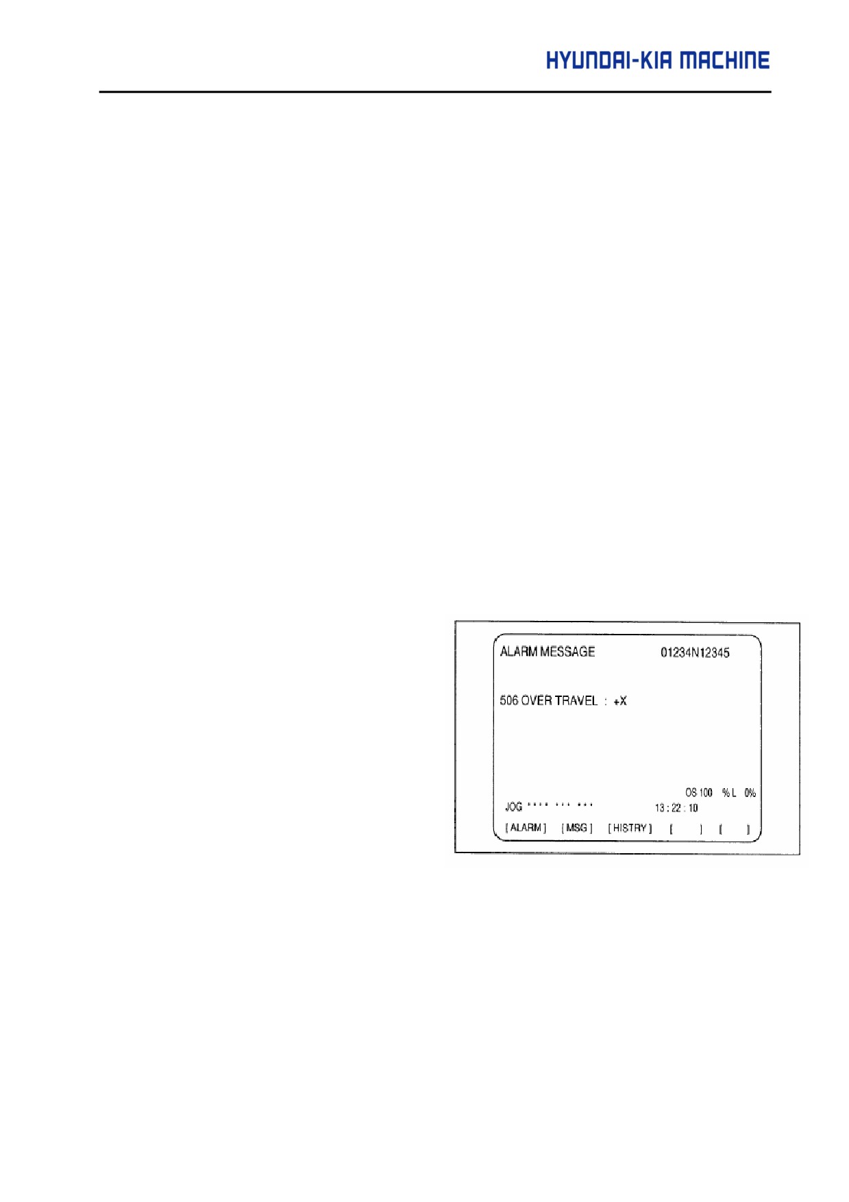
It will be exhausted by pressing the "[CALL/BZ
OFF]" switch of Operating Panel.
5-82
V. REPAIR AND PRESERVATION
1)
1 color (Yellow)
Illuminated if the alarm lamp is on by the occurence of each alarm or stop of the
programs(M00, M01, M02, M30). If the alarm lamp is on, the machine stops temporarily and
displays the text of alarm on the screen.
2)
2 colors (Green and Red)
a. Green: Illuminated when the automatic program being performed.
b. Red: Illuminated when each alarm occures or the program stop(M00, M01, M02 M30).
For the others, it is the same with para. 1).
3)
3 colors (Green, Yellow and Red)
a. Green'- Illuminated when the automatic program being performed.
b. Yellow: Illuminated when the program stops(MOO, M01, M02, M30).
c. Red: Illuminated when each alarm occurs. For the others, it is the same with para. 1)
3-9-3. Alarm Indicator
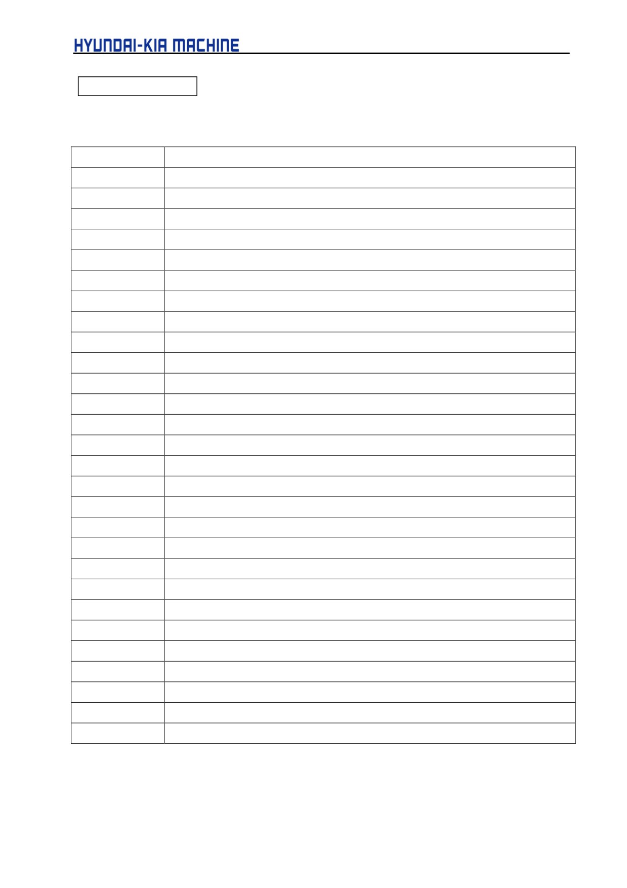
1) When the alarm generally has occurred, the screen will be converted to the alarm
automatically and the message "AL" or "A/B"(battery alarm) flashed in the lower right of
screen.
2) The upper side
(ALARM) of alarm
diagnostic screen indicates the NC
alarm and the lower
(MESSAGE)
displays up to 4 PC alarms. ft1
3) To delete the alarm, remove the cause
and then press the RESET button. If
the alarm has not been deleted by
pressing the RESET key, it will remain
the alarm state and not be returned unless the power turned OFF.
5-83
ALARM MESSAGE
[FANUC 0/-TB]
AL-NO.
MESSAGE
2000
AL-O CP & FUSE TRIP
2001
AL-1 SPINDLE AMP ALARM
2002
AL-2 TAILSTOCK MOTOR OVERLOAD
2003
AL-3 LUB. OIL LACK/FAULT
2004
AL-4 HYD. PRESSURE DROP
2005
AL-5 AIR PRESSURE DROP
2006
AL-6 X-AXIS TORQUE ALARM
2007
AL-7 Z-AXIS TORQUE ALARM
2010
AL-10
2011
AL-11
2012
AL-12 POWER OFF NC ALARM
2013
AL-13 DOOR OPERATION INHIBIT
2014
AL-14 SPINDLE ROTATION INHIBIT
2015
AL-15 SPINDLE COMMAND TIME OVER
2016
AL-16 Q-SETTER ARM DOWN
2017
AL-17 ROBOT FAULT
2020
AL-20 ZERO RETURN INCOMPLETED
2021
AL-21
2022
AL-22
2023
AL-23 TAIL-STOCK SET NG
2024
AL-24 POWER OFF PROGRAM END
2025
AL-25 SPINDLE ORIENTATION FAIL
2026
AL-26
2027
AL-27 TOOL LIFE END
2030
AL-30 CHUCK CLAMP NG
2031
AL-31 DOOR CLOSE NG,
2032
AL-32 CENTER POSITION NG
2033
AL-33 SPINDLE STOP INCOMPLETED
5-84
V. REPAIR AND PRESERVATION
AL-NO.
MESSAGE
2034
AL-34 LNS MULTI BAR FEEDER ALARM
2035
AL-35 END OF BAR
2036
AL-36 COUNT UP
2037
AL-37 SPINDLE-DOOR INTERLOCK
2040
AL-40 BAR FEEDER NOT READY
2041
AL-41 TURRET INDEX INHIBIT ZONE
2042
AL-42 HYDRAULIC MOTOR OVERLOAD
2043
AL-43 COOLANT MOTOR OVERLOAD
2044
AL-44
2045
AL-45
2046
AL-46 X-AXIS OVERLOAD
2047
AL-47 Z-AXIS OVERLOAD
2050
AL-50 CHIP CONVEYOR OVERLOAD
2051
AL-51
2052
AL-52 PART CATCHER FAULT
2053
AL-53 PC PARAMETER SET NG
2054
AL-54 PROGRAM START PB NG
2055
AL-55
2056
AL-56
2057
AL-57
2060
AL-60 TURRET INDEX POWER OFF
2061
AL-61 TURRET SETUP ERROR
2062
AL-62 TURRET AMP ALARM
2063
AL-63 TURRET BATTERY ALARM
2064
AL-64 TURRET INDEX TIME OVER
2066
AL-66 TURRET INDEX CONDITION NG
2067
AL-67 TURRET COMPULSORY UNCLAMP
2075
AL-75 TURRET ADJUST MODE
2131
AL-131 COMMAND TOOL No.NG
2133
AL-133 POWER UNIT OFF REQUIRE
5-85
3-9-4. Parameter
Parameter is the important factor in determining the characteristics and functions of machine.
There are ones for determining the standard specification and selective one, classification,
function, or the capacity or the level of the desired performance. 1) Kinds and major contents a. NC
parameter
See the NC parameter Table.
For the information, see "FANUC operating manual". (2) How to treat the parameter
Each parameter (data) has been set at the factory and doesn' t need revise or set, unless otherwise
stated (Except for the custom macro, backlash/pitch error compensation areas). In addition, when
shipping the machine, the values of NC and PC parameter should be tagged on the machine, so
keep and prepare if for further use.
5-86
V. REPAIR AND PRESERVATION
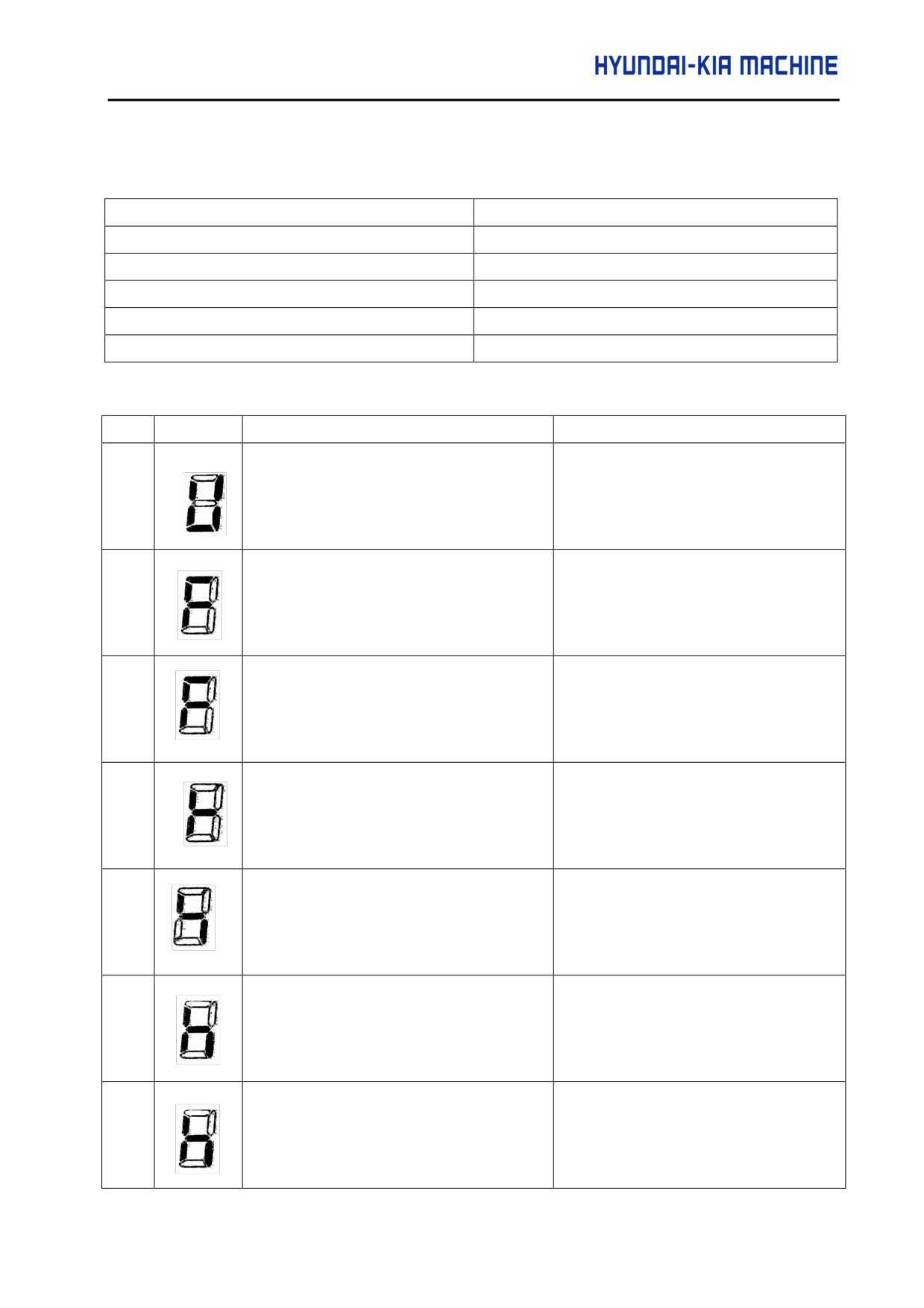
3-9-5. Alarm display and corresponding Coutermeasures
Alarm No.
Alarm type
000-299
Program/Setting Alarm
300-399. 401
Pulse Coder Alarm
400-499
Servo Alarm
500-599
Over Travel Alarm
-
System/ I/O Link Alarm
[Program/Setting Alarm (PS Alarm)]
No.
LED
Description
Countermeasure
000
A parameter that requires power-down has
Turn the power off, then back on.
been specified.
011
The specified feedrate is zero.
Check the feedrate parameter specified
with a function code.
013
The specified feedrate (maximum feedrate)
Check the value of parameter No. 043,
is zero.
which indicates the maximum feedrate
that can be specified.
070
More than 32 blocks have been registered
Reduce the number of registered blocks
for a buffering operation.
to 32
085
Input from the reader/punch interface or
Correct the baud rate of the input/output
the like caused ah overrun, parity, or
unit (always 4800) or other settings.
framing error.
086
Input from the reader/punch interface or
Turn the reader/punch on. Check the
the like includes an input/output unit
cable connection.
operation ready signal (DR) that is set to
off.
087
After input from the reader/punch interface
Check the cable connection.
or the like stops, character input does not
stop even though ten characters have been
input.
5-87
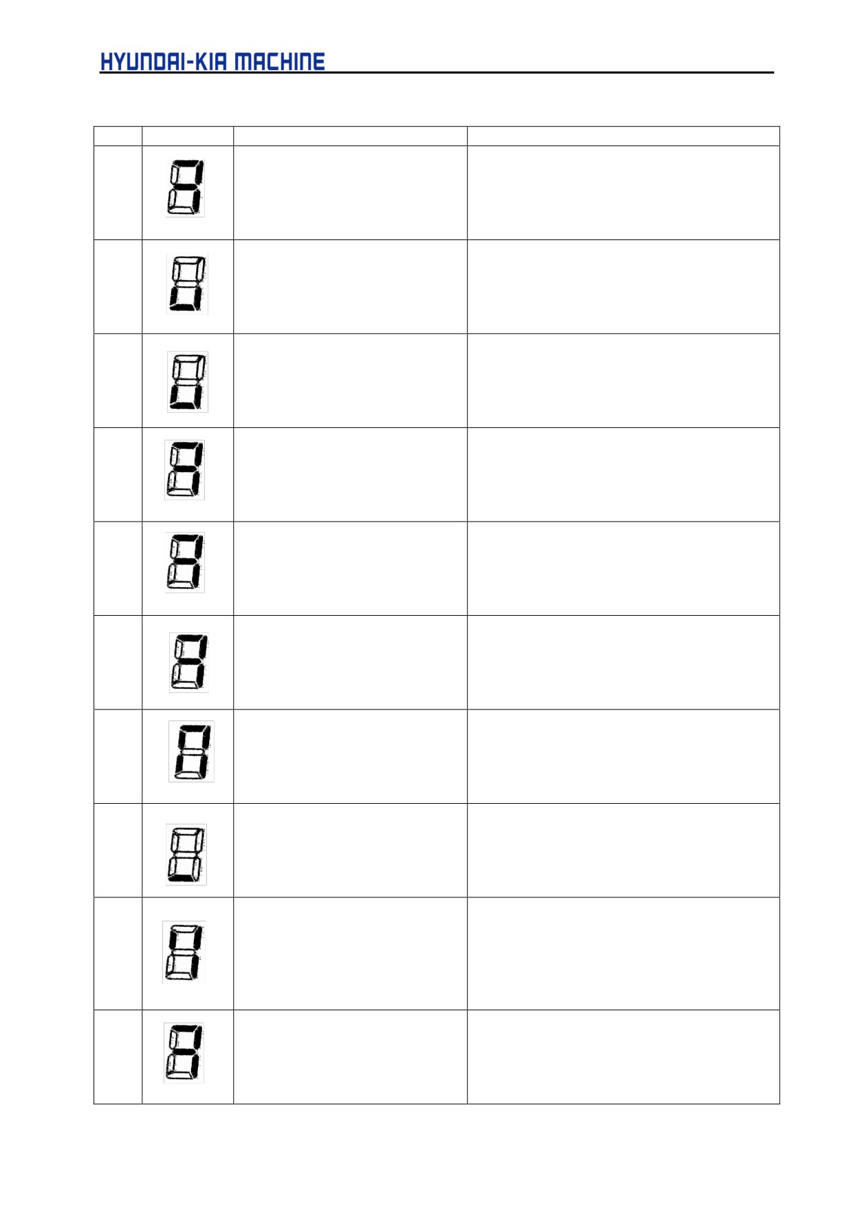
[Program/Setting Alarm(PS Alarm)]
No.
LED
Description
Countermeasure
090
Reference position setting
Move the tool in the direction of reference
cannot be executed normally.
position return in jog mode at a speed that
causes the servo position error to exceed
128. Then, specify another reference position
setting.
093
A first to third reference position
Set the reference position.
return cannot be executed
because the referent position
has not yet been established.
224
The reference position has not
Set the reference position.
yet been established. This
occurs only when the ZRTN bit
of parameter No.00l is set to 0.
250
Input data 1 is invalid.
Check input data 1, specified with a function
code.
251
Input data 2 is invalid.
Check input data 2, specified with a function
code.
254
Enable coder or mode disabled
Check code instruction, specified with a
function code. Check the mode.
255
Operation cannot be activated
Check the mode. Check whether a block is
because an invalid mode is
being executed.
specified or because block
execution is in progress.
290
The interface switch signal
Switch the signal after block execution stops.
(DRC) was switched during
block execution.
291
The speed of an axial movement
Turn the reader/punch on. Check the cable
specified by an external pulse
connection.
has exceeded the upper limit.
This occurs only when the
EPEXA bit of parameter No.00l
is set to 1.
292
A checksum error for the
Parameters are cleared. Set the parameters
battery-powered memory was
again. If this alarm subsequently recurs,
detected.
replace the unit
5-88
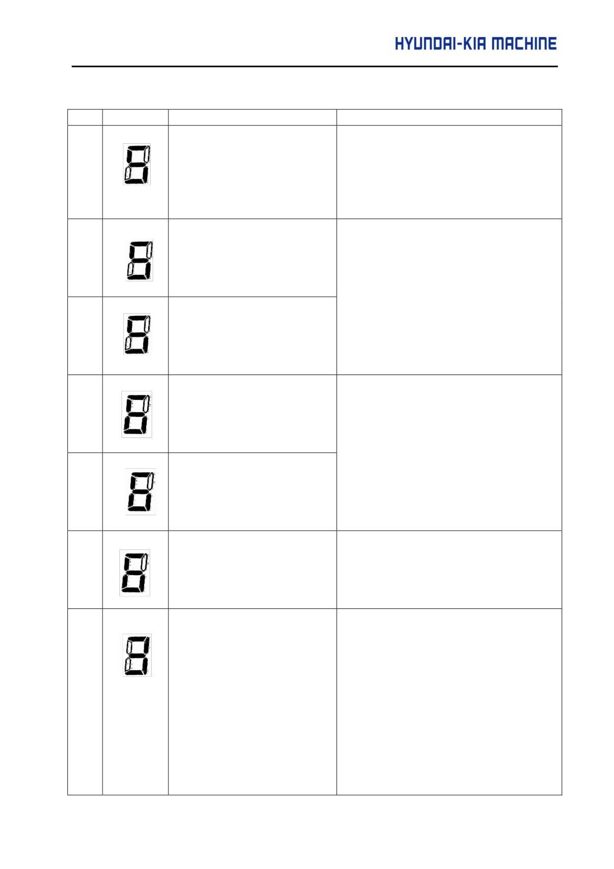
V. REPAIR AND PRESERVATION
[Pulse Coder Alarm]
No.
LED
Description
Countermeasure
300
Check the continuity of the signal cable. If the
A communication error (DTER)
cable is normal, the pulse coder may be
for the serial pulse coder was
defective. Turn the power off. If the alarm
detected.
recurs when the power is reapplied, replace
the serial pulse coder, together with the
motor.
301
A
communication
error
(CRCER) for the serial pulse
coder was detected.
Check the continuity of the signal cable. If the
cable is normal, the pulse coder or servo unit
may be defective. This error can also be
302
A communication error (STBER)
caused by external noise.
for the serial pulse coder was
detected.
303
A communication error (LDAL)
for the serial pulse coder was
detected.
Turn the power off. If this alarm recurs when
the power is re-applied, replace the motor.
304
A communication error (PMAL)
for the serial pulse coder was
detected.
305
Turn the power off. If this alarm recurs when
A miscount alarm (CMAL) for
the power is re-applied, replace the motor. If
the serial pulse coder was
the alarm does not recur, re-start the
detected.
operation form reference position return.
306
This alarm is issued when the amplifier has
overheated, causing the thermostat to trip.
Possible causes include an excessively high
The motor has overheated
ambient temperature and excessively strict
(OHAL).
operation conditions.
Check the actual
cause. Disconnect the power of about ten
minutes, then release the
emergency,
replace the amplifier.
5-89
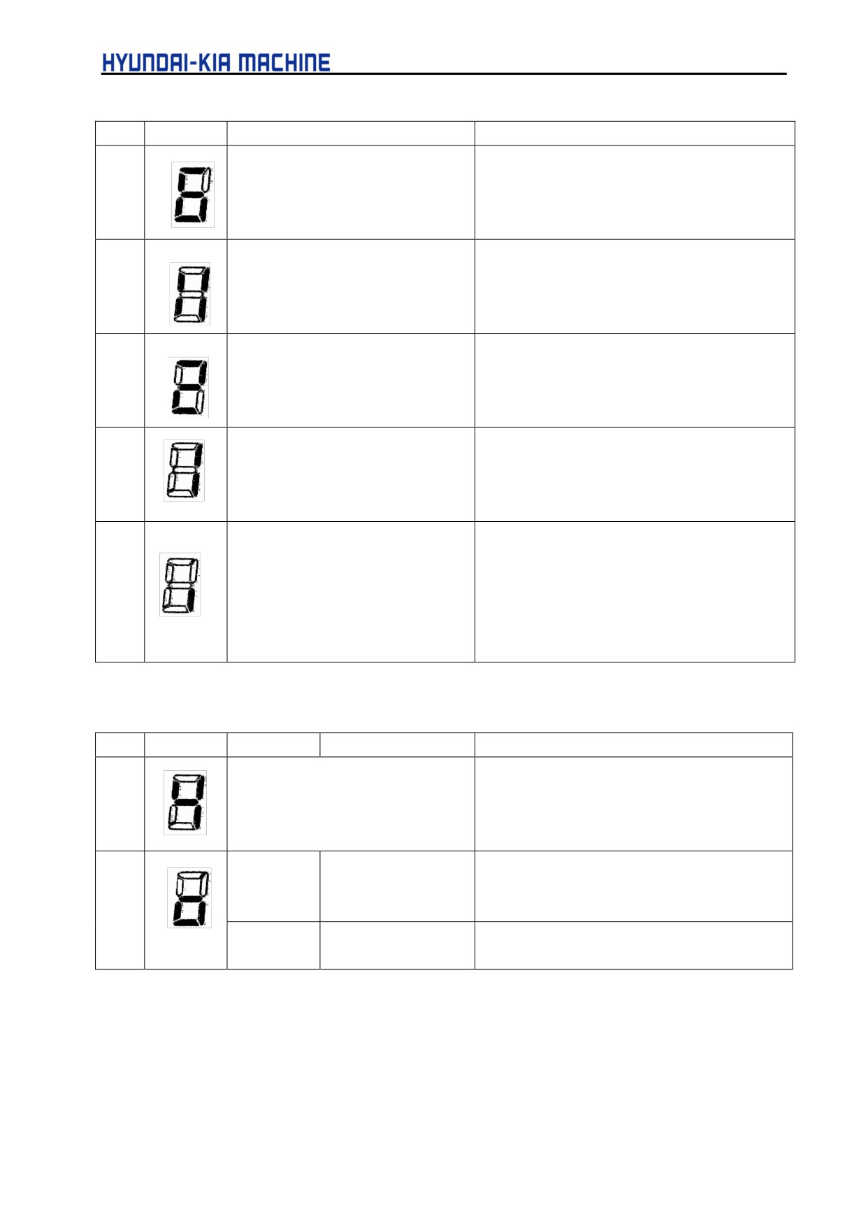
No.
LED
Description
Countermeasure
308
A soft phase alarm (SPHAL)was
Turn the power off. This alarm may be caused
detected.
by noise.
319
When the absolute pulse coder is
Cause the motor rotate through more than
used, the motor has not yet
one turn in jog feed mode, then turn the power
rotated through more than one
off then back on.
turn after the first power-up.
350
The battery voltage of the
Replace the battery.
absolute pulse coder is low.
Restart the operation from reference position
return.
351
The battery voltage of the
Replace the battery.
absolute pulse coder is low.
401
Communication error of Serial
Check if the signal cable of pulse coder
Pulse Coder was detected.
being connected. If the cable being ok, there
could be an error in the pulse coder or Servo
AMP Unit. Otherwise, it could be caused by
the outer Noise. Refer to the Precautions of
Noise in the manual.
[Servo Alarm]
No.
LED
Description
Countermeasure
400
The servo motor has overheated
Turn the power off. After a while, turn the power
(estimated value)
back on. Possible causes include an
excessively high ACC/DEC frequency.
403
SVU-12
The cooling fans
The load on the motor may be too high.
SVU-20
have overheated.
Re-examine the load conditions.
(Hardware detection)
SVU-40
This alarm was not
The load on the motor may be too high.
SVU-80
occurred.
Re-examine the load conditions.
5-90
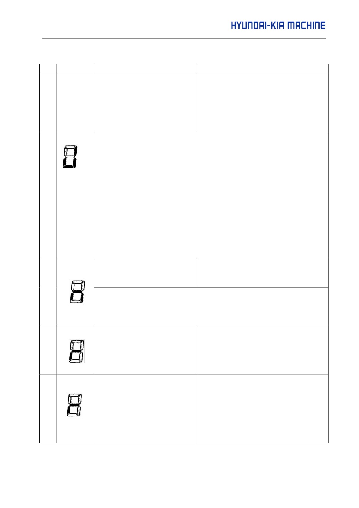
V. REPAIR AND PRESERVATION
No.
LED
Description
Countermeasure
The regenerative discharge unit
This alarm is issued when the average
has overheated.
regenerative discharge energy is too high
(when the ACC/DEC frequency is too high,
for example).
When the regenerative discharge resistor is not being used, check whether a dummy
connector is fitted to the CX11-6 connector.
404
1) The average regenerative discharge energy may be too high. Decrease the
ACC/DEC frequency.
2) The thermostat line of the separate regenerative discharge unit may not be
connected properly. Check the connection.
3) The thermostat of the separate regenerative discharge unit may be defective.
Disconnect the separate regenerative discharge unit, then check the thermostat.
If the thermostat is open even through the separate regenerative discharge unit
is cool, replace the separate regenerative discharge unit.
If (1) to (3) are not the cause of the alarm, replace the servo amplifier.
405
Reference position return could
Re-execute reference position return.
not be executed correctly.
If setting parameter No.032 (CMR) to the value between 4 and 96, an alarm could be
occurred. This time, set the parameter No.001 #4(N405) to "1" to prevent the alarm
occurred.
410
The servo position error in the
Determine the mechanical cause of the large
stop state is larger than the value
position error. If no mechanical cause is
specified in parameter No. 110.
found, specify a larger value for the
parameter.
411
The servo position error during
Determine the mechanical cause of the large
movement is larger than the value
position error. If no mechanical cause is
specified in parameter No. 182.
found, apply any of the following
counter-measures:
• Specify a larger value for the parameter
• Specify a lower federate.
• Increase the time contants.
5-91
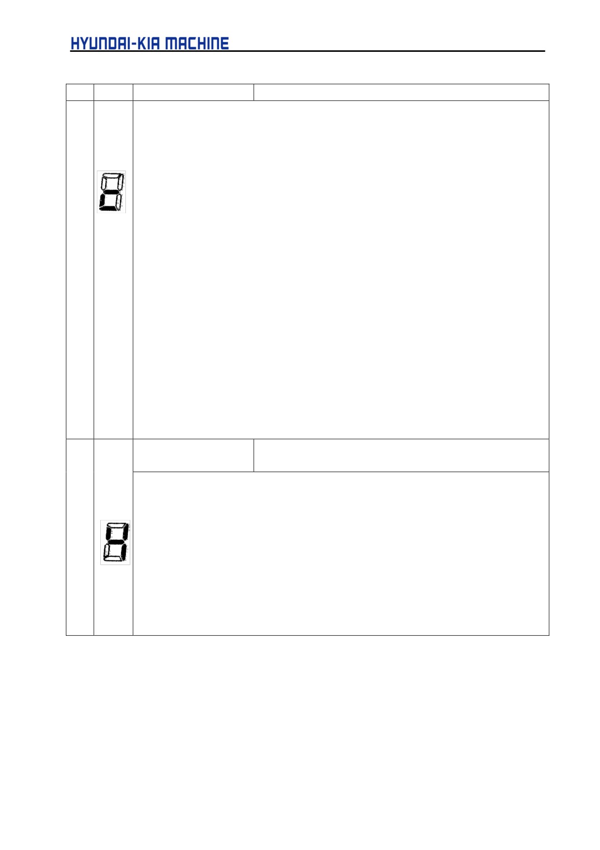
No.
LED
Description
Countermeasure
An overcurrent alarm is issued. This alarm is issued when an excessively large current
flows in the main circuit.
1) Check whether a valid motor number is specified in parameter No. 30.
2) Check whether the standard values are specified in the current control parameters for
servo control.
Correct current control is possible only when the standard values are specified for
following parameter.
=> No. 70, 71, 72, 78, 79, 84, 85, 86, 87, 88, 89, 90
3) Disconnect the power line from the amplifier connector. Then, release the emergency
412
stop state.
=> If the overcurrent alarm continues to be issued, replace the AMP.
=> If no overcurrent alarm is issued, go to (4).
4) Disconnect the power line from the AMP connector. Check the insulation between the
ground and each of U, V, and W. If the insulation is satisfactory, go to (5).
If a short-circuit is detected, disconnect the power line from the motor connector. Then,
check the insulation between the ground and each of U, V, and W of the motor.
If the insulation is satisfactory, replace the power line.
5) Connect the power line. Observe the waveform of the motor current (IR, IS) while the
motor is accelerating or decelerating. If the motor current (IR, IS) does not exhibit a
normal sine wave, replace the amplifier.
6) If (1) to (4) above are not the cause of the alarm, the pulse coder, command cable, or
internal hardware of the CNC may be defective.
A DC link overvoltage
This alarm is issued when the DC voltage of time main circuit
alarm is issued.
power is too high.
1) The supply voltage for dynamic power may exceed the rated value. Check the voltage. If
the voltage is too high, reduce the voltage to an appropriate level.
2) The regenerative discharge unit may not be properly connected. Check the connection.
413
3) The resistance of the separate regenerative discharge unit may be abnormal Disconnect
the separate regenerative discharge unit, then check the resistance. If the resistance is
not within ±20% of the predetermined resistance, replace the separate regenerative
discharge unit. If (1) to (3) are not the cause of the alarm, replace the servo AMP.
5-92
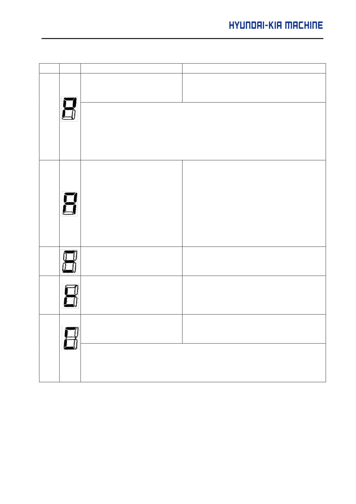
V. REPAIR AND PRESERVATION
No.
LED
Description
Countermeasure
A DC link low voltage alarm is
This alarm is issued when the DC voltage of the
issued.
main circuit power is too low.
414
1) The external circuit breaker may be turned off. Check the circuit breaker.
2) The supply voltage for dynamic power is lower than the rated value. Check the voltage.
If the voltage is too low, increase it to an appropriate level.
3) The external magnetic contactor may not be connected properly. Check the connection.
If (1) to (3) are not the cause of the alarm, replace the servo AMP.
Check the following parameter :
No. 30: Is the specified motor type correct?
No. 31: Is the specified direction of rotation of the
417
A parameter has been specified
motor correct?
incorrectly
No. 106: Is the denominator of the number of
pulses per single revolution of the motor "0"?
No.
180: Is the specified reference counter
capacity 0 or a negative value?
418
A DO alarm is issued.
Replace the servo unit
423
The specified speed exceeds
Re-examine the CMR and speed settings.
32767000 detection units per
second.
The cooling fan has stopped.
This alarm is issued when the fan motor built into
the servo AMP has failed.
425
1) Check that the fan is not clogged with foreign matter.
2) Check that the power connector of the fan is connected properly.
3) Replace the fan or servo unit.
5-93
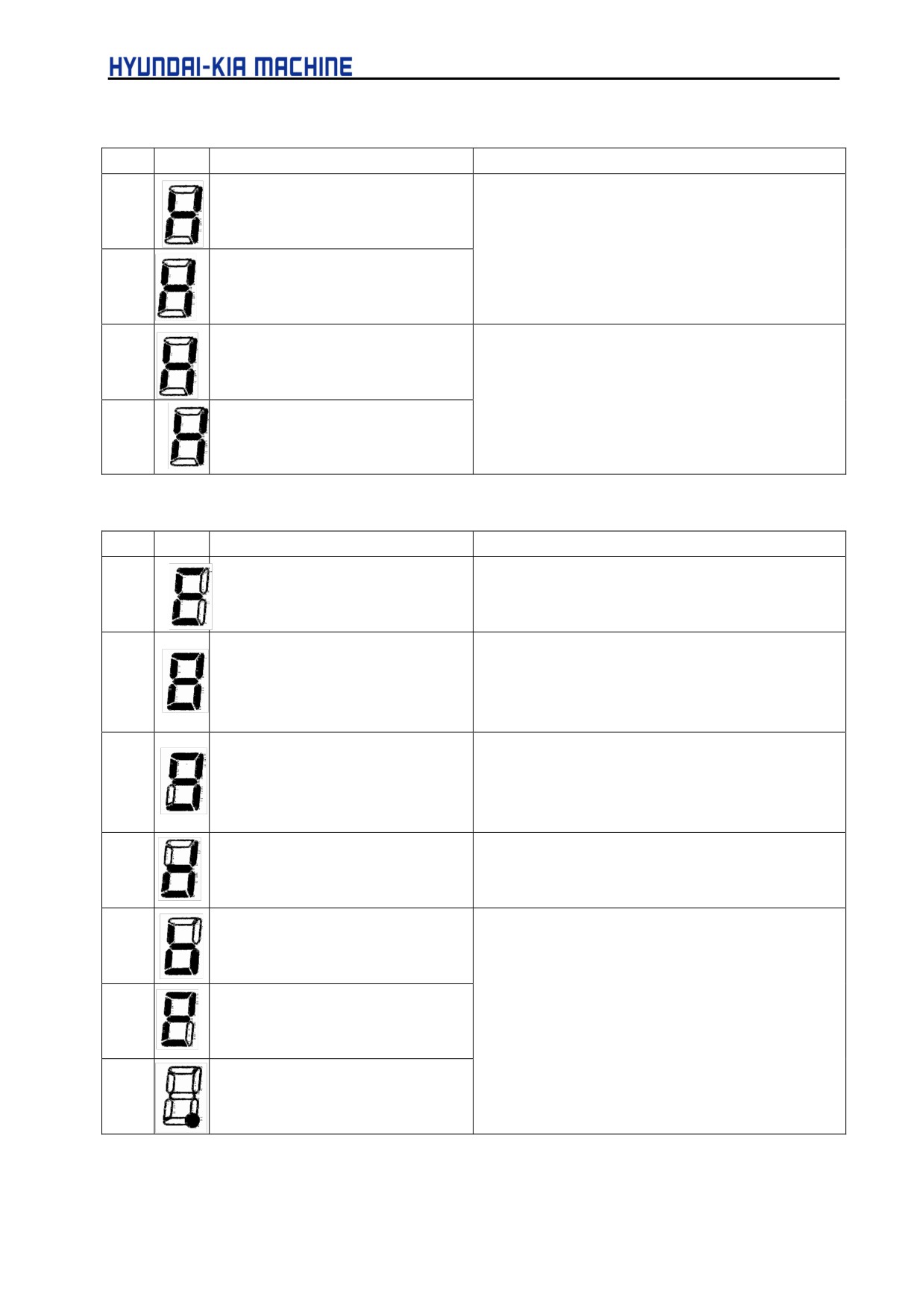
[Over Travel Alarm]
No.
LED
Description
Countermeasure
500
The positive stroke limit has been
Check whether
*+OT and *-OT are connected
exceeded.
correctly. Check whether a correct move command
is specified. Move the tool in the opposite direction
501
The negative stroke limit has been
in jog mode, then perform a reset.
exceeded.
510
The positive soft stroke limit has
Check whether appropriate values have been
been exceeded.
specified for parameters No. 142 and 143. Check
whether a valid move command is specified. Move
511
The negative soft stroke limit has
the tool in the opposite direction in jog mode, then
been exceeded.
per-form a reset.
[System Alarm]
No.
LED
Description
Countermeasure
-
An error was detected in the RAM
Replace the unit.
write/read test at power-up.
-
An error was detected in the data
Turn the power off then back on. Then, re-enter the
collation
check
for
the
parameters. If this alarm recurs, replace the unit.
battery-powered memory.
-
A data transfer alarm for the
Replace the unit.
battery-powered memory has
been issued.
-
A watch dog alarm was issued.
Turn the power off then back on. If this alarm recurs,
replace the unit.
-
A checksum alarm for the control
software ROM is issued.
-
A checksum alarm for the ROM
that is built into the CPU is issued.
Replace the unit.
-
An error was detected in the
control circuit.
5-94
V. REPAIR AND PRESERVATION
[I/O Link Alarm]
No.
LED
Description
Countermeasure
A FANUC I/O link error
Turn off the power the all units connected to the line.
-
occurred. A unit connected to
Then, turn on the slave devices, followed by the
the line was turned off.
master device.
[No LED display]
No.
LED
Description
Countermeasure
No indi-
The control circuit is not
1) Check the 24-VDC control supply voltage. If the
ca tors
operating normally.
voltage is low, increase the voltage to an
-
lit
appropriate level.
2) Check whether a fuse in the servo unit has
blown.
If (1)~(2) are not the cause, replace the servo AMP.
5-95
3-9-6. Error Codes Serial Spindle)
Note
Note that the meanings of the the SPM indictions differ depending on which LED, the redor yellow LED,
is on.
When the red LED is on, the SPM indicates the number of an alarm generated in thee serial spindle.
No.
Faulty location and remedy
Description
00
Check the *EPS and MRDY sequence. (For
Although neither *EPS (emergency stop signal;
MRDY, pay attention to the parameter setting
there are two types of signals including the
regarding the use of the MRDY signal(bit 0 of
PMC signal and PSM contact signal (*2)) nor
parameter No.4001).)
MRDY (machine ready signal) is input, SFR
(forward rotation signal)/SRF (reverse rotation
signal)/ ORCM (orientation command) is input.
01
Check the spindle motor speed detector
When the spindle motor has a high-resolution
parameter (bits
2,
1, and
0 of parameter
magnetic pulse coder (Cs sensor) (bits 6 and 5
No.4011)
of parameter No.4001 are set to
0 and 1,
respectively), 128 /rev is to be set for the speed
detector (bit 2, 1. and 0 of parameter No.4011
are set to 0, 0. and 1, respectively). However, a
value other than 128 /rev is set. In this case, the
motor is not excited.
02
Check the parameters for the detector for Cs
Although use of a high-resolution magnetic
contour control (bit 5 of parameter No.4001
pulse coder(bit 5 of parameter No.4001 = 1) or
and bit 4 of parameter No.4018)
use of the Cs contour control function by the
sensor (bit 4 of parameter No.4018 = 1) is not
set. a Cs control command is input. In this case,
the motor is not excited.
03
Check the position coder signal parameter
Although use of the position coder signal (bit 2
(bit 2 of parameter No.4001)
of parameter No.4001 = 1) or use of the Cs
contour function by the sensor
(bit
4 of
parameter No.4018 = l)is not set, a Cs control
command is input. In this case, the motor is not
excited.
5-96
V. REPAIR AND PRESERVATION
No.
Faulty location and remedy
Description
04
Check the orientation software option.
Although the orientation option is not set, an
orientation command(ORCM) is input.
05
Check the spindle output switching software
Although the output switching option is not set,
option and power line status signal(RCH).
the lowspeed winding is selected(RCH=1).
06
Check the sequence(CON, SFR, SRV).
Although the Cs contour control mode is
specified, SFR/SRV is not input.
07
Check the sequence (SFR. SRV).
Although the servo mode (rigid tapping, spindle
positioning) is specified, SFR/SRV is not input.
09
Check the sequence(SPSYC, SFR. SRV).
Although spindle synchronization mode is
specified, SFR/SRV is not input.
10
During execution of the C-axis control
Although Cs contour control mode is set,
command, do not specify another operation
another operation mode (servo mode, spindle
mode. Before entering another mode, cancel
synchronization, or orientation) is specified.
the Cs contour control command.
11
During execution of the servo mode
Although servo mode (rigid tapping, or spindle
command, do not specify another operation
positioning) is set, another operation mode(Cs
mode. Before entering another mode, cancel
contour control, spindle synchronization, or
the servo mode.
orientation) is specified.
12
During
execution
of
the
spindle
Although spindle synchronization is being
synchronization command, do not specify
performed, another operation mode (Cs contour
another operation mode. Before entering
control, servo mode, or orientation) is specified.
another mode, cancel the spindle
synchronization command.
13
During execution of the orientation command,
Although the orientation command is being
do not specify another operation mode.
executed, another operation mode (Cs contour
Before entering another mode, cancel the
control, servo mode, or orientation) is specified.
spindle synchronization command.
14
Input the SFT or SRV signal.
The SFT and SRV signals are both input at the
same time.
15
Check bit 5 of parameter No.4000 and PMC
When bit 5 of parameter No.4000 is set to 1
signal(CON).
indicate the presence of the differential speed
mode function, Cs contour control is specified.
5-97
No.
Faulty location and remedy
Description
16
Check bit 5 of parameter No.4000 and PMC
When bit 5 of parameter No.4000 is set to 0 to
signal (DERMD).
indicate the absence of the differential speed
mode command (DEFMD) is input.
17
Check bits 2, 1 and 0 of parameter No.4011.
Setting of the speed detector parameter (bit 2.
1, and 0 of parameter No.4011) is invalid. (The
corresponding speed detector is not present.)
18
Check bit 2 of parameter No.4001 and PMC
Although bits 2 of parameter No.4001 is set to 0
signal(ORCM).
not to use the position coder signal, a command
for orientation by a position coder (ORCMA) is
input.
19
During execution of the orientation command,
Although orientation by a magnetic sensor is
do not specify another operation mode.
being performed, another operation mode is
Before entering another mode, cancel the
specified.
orientation command.
20
Check bit 5 of parameter No.4001, bit 5 of
When the use of the slave operation mode
parameter No.4014, and bit of parameter
function is set(bit 5 of parameter No.4014 = 1),
No.4018.
the use of a high-resolution magnetic pulse
coder (bit 5 of parameter No.4001 = 1) or the
use of the Cs contour control function by the
sensor
(bit
4 of parameter No.4018
= l)is
specified. These items cannot be set at the
same time.
21
Input the slave operation mode command
Although position control (such as servo mode
(SLV) in normal operation mode.
or orientation) is being performed, a slave
operation mode command (SLV) is input.
22
Input the position control command in normal
Although slave operation mode is set(SLVS = l),
operation mode
a position control command (such as servo
mode or orientation) is input.
23
Check bit 5 of parameter No.4014 and PMC
Although bit 5 of parameter No.4014 is set to 0
signal(SLV)
not to use the slave operation mode function, a
slave operation mode command (SLV) is input.
5-98
V. REPAIR AND PRESERVATION
No.
Faulty location and remedy
Description
24
Check the PMC signal (INCMD). Perform
Orientation is performed in incremental
orientation by specifying an absolute position
operation mode (INCMD = 1) fist, then the
first.
absolute position command (INCMD = 0) is
input.
25
Check the spindle amplifier specifications and
Although the spindle amplifier SPM type 4 is not
parameter setting
(bit
4 of parameter
used, the use of the Cs control function by the
No.4018)
sensor is set (bit 4 of parameter No.4018 = 1).
Note
PSM contact signal
Between EPS1 and EPS2 on the PSM
Contact open
: Emergency stop
Contact closed
: Normal operation
5-99