FANUC Series 0i-MODEL F. For Lathe System OPERATOR'S MANUAL (B-64604EN-1/01) - page 11
 

  Index      Manuals     FANUC Series 0i-MODEL F. For Lathe System OPERATOR'S MANUAL (B-64604EN-1/01)


Search            copyright infringement  


Content      ..     9      10      11      12     ..


FANUC Series 0i-MODEL F. For Lathe System OPERATOR'S MANUAL (B-64604EN-1/01) - page 11


 B-64604EN-1/01

 PROGRAMMING 

5.COMPENSATION FUNCTION


- 153 - 

5.2 

OVERVIEW OF TOOL NOSE RADIUS COMPENSATION 
(G40-G42) 

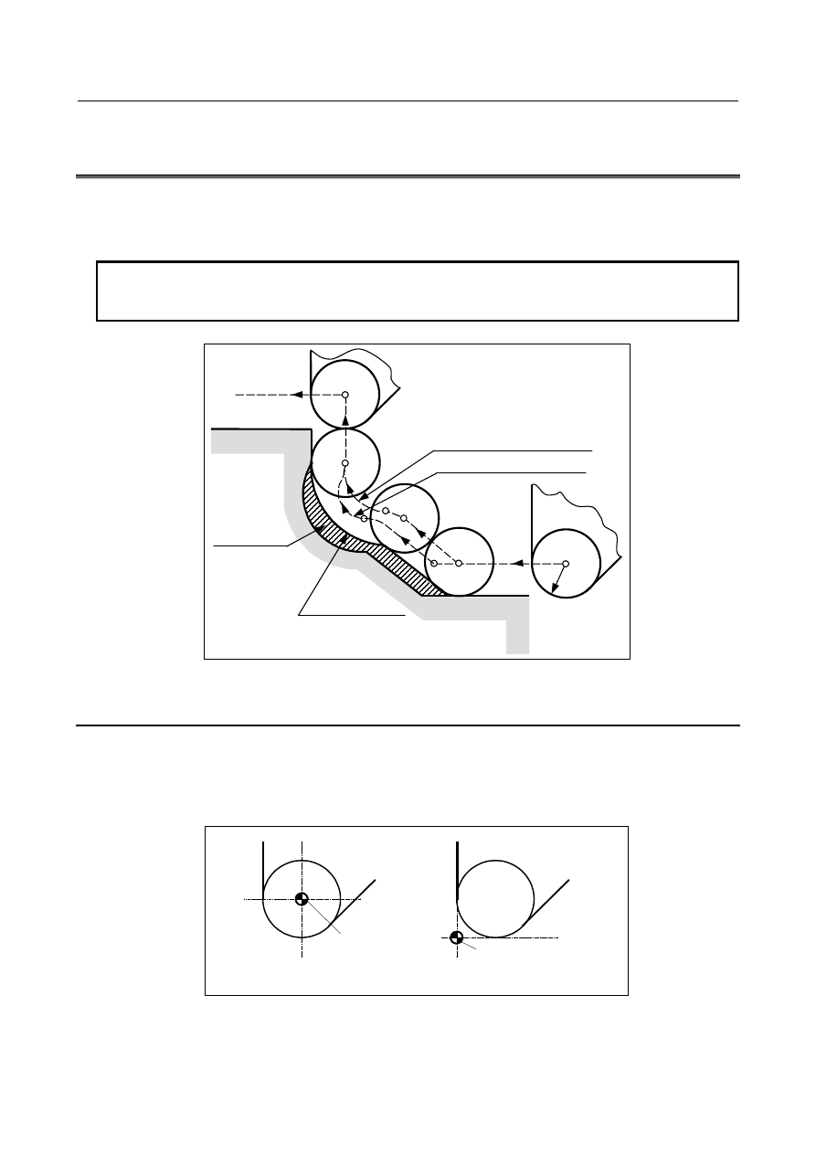
It is difficult to produce the compensation necessary to form accurate parts when using only the tool 
offset function due to tool nose roundness in taper cutting or circular cutting. The tool nose radius 
compensation function compensates automatically for the above errors. 
 

NOTE 


When bit 7 (NCR) of parameter No.8136 is 0, "Tool nose radius compensation" 
can be used. 


R

Workpiece

Insufficient
depth of
cutting

Shape processed without tool

nose radius compensation

Tool path without compensation

Tool path with compensation

Tool nose


Fig 5.2 (a) Tool path of tool nose radius compensation 


5.2.1 

Imaginary Tool Nose 

The tool nose at position A in Fig. 5.2.1 (a) does not actually exist. 
The imaginary tool nose is required because it is usually more difficult to set the actual tool nose radius 
center to the start point than the imaginary tool nose. 
Also when imaginary tool nose is used, the tool nose radius need not be considered in programming. 
The position relationship when the tool is set to the start point is shown in Fig. 5.2.1 (a). 

A

Start point

Start point

When programmed using the tool
nose center

When programmed using the
imaginary tool nose


Fig. 5.2.1 (a) Tool nose radius center and imaginary tool nose 


5.COMPENSATION FUNCTION

 PROGRAMMING 

 B-64604EN-1/01


- 154 - 

 CAUTION 


In a machine with reference positions, a standard position like the turret center 
can be placed over the start point. The distance from this standard position to 
the nose radius center or the imaginary tool nose is set as the tool offset value. 


Setting the distance from the standard position to the tool nose radius center as 
the offset value is the same as placing the tool nose radius center over the start 
point, while setting the distance from the standard position to the imaginary tool 
nose is the same as placing the imaginary tool nose over the standard position. 
To set the offset value, it is usually easier to measure the distance from the 
standard position to the imaginary tool nose than from the standard position to 
the tool nose radius center. 


OFX

(Tool offset
in X axis)

OFZ
(Tool offset
in Z axis)

Setting the distance from the standard position
to the tool nose center as the tool offset value

Setting the distance from the standard position to
the imaginary tool nose center as the tool offset

value

The start position is placed over the tool nose center

The start position is placed over the imaginary tool
nose

OFX
(Tool offset

in X axis)

OFZ
(Tool offset
in Z axis)


Fig. 5.2.1 (b) Tool offset value when the turret center is placed over the start point 


Unless tool nose radius compensation is
performed, the tool nose center path is the
same as the programmed path.

If tool nose radius compensation is used, accurate

cutting will be performed.

Tool nose center path

Programmed path

Start-
up

Start-
up

Programmed path

Tool nose center path


Fig. 5.2.1 (c) Tool path when programming using the tool nose center 


Without tool nose radius compensation, the
tool nose radius center path is the same as

the programmed path.

With tool nose radius compensation, accurate
cutting will be performed.

Imaginary tool
nose path

Imaginary tool
nose path

Start-
up

Start-
up

Programmed path

Programmed path


Fig. 5.2.1 (d) Tool path when programming using the imaginary tool nose 


 B-64604EN-1/01

 PROGRAMMING 

5.COMPENSATION FUNCTION


- 155 - 

5.2.2 

Direction of Imaginary Tool Nose 

The direction of the imaginary tool nose viewed from the tool nose center is determined by the direction 
of the tool during cutting, so it must be set in advance as well as offset values. 
The direction of the imaginary tool nose can be selected from the eight specifications shown in the Fig. 
5.2.2 (a) below together with their corresponding codes. Fig. 5.2.2 (a) illustrates the relation between the 
tool and the start point. The following apply when the tool geometry offset and tool wear offset option are 
selected. 

Imaginary tool nose number 1

Imaginary tool nose number 2

Imaginary tool nose
number 3

Imaginary tool nose
number 4

Imaginary tool nose number 5

Imaginary tool nose number 6

Imaginary tool nose number 7

Imaginary tool nose number 8

X

Z

G18

Y

X

G17

Z

Y

G19


Fig. 5.2.2 (a) Direction of imaginary tool nose 


Imaginary tool nose numbers 0 and 9 are used when the tool nose center coincides with the start point. Set 
imaginary tool nose number to address OFT for each offset number. 
Bit 7 (WNP) of parameter No. 5002 is used to determine whether the tool geometry offset number or the 
tool wear offset number specifies the direction of the virtual tool nose for tool nose radius compensation. 

Imaginary tool nose number 0 or 9


5.COMPENSATION FUNCTION

 PROGRAMMING 

 B-64604EN-1/01


- 156 - 

5.2.3 

Offset Number and Offset Value 

Explanation 

  -  Offset number and offset value 

Tool nose radius compensation value

(Tool nose radius value)


When the tool geometry compensation and tool wear compensation is disabled (bit 6 (NGW) of parameter 
No. 8136 is set to 1), the contents displayed on the tool offset screen become as Table 5.2.3 (a): 
 

Table 5.2.3 (a) Offset number and offset value (example) 

Offset number 
Up to 200 sets 

OFX (Offset 

value on X 

axis) 

OFZ (Offset 

value on Z axis)

OFR (Tool nose 

radius compensa-

tion value) 

OFT (Direction of 

imaginary tool 

nose) 

OFY (Offset 

value on Y axis)

001 
002 
003 
004 
005 

0.040 
0.060 
0.050 


0.020 
0.030 
0.015 


0.200 
0.250 
0.120 


0.030 
0.040 
0.025 


When the tool geometry compensation and tool wear compensation is enabled (bit 6 (NGW) of parameter 
No. 8136 is set to 0), the contents displayed on the tool offset screen become as Table 5.2.3 (b) and Table 
5.2.3 (c): 
 

Table 5.2.3 (b) Tool geometry offset (example) 

Geometry 

offset number 

OFGX  

(X-axis 

geometry 

offset amount) 

OFGZ  

(Z-axis 

geometry offset 

amount) 

OFGR  

(Tool nose radius 

geometry offset 

value) 

OFT (Imaginary 

tool nose 

direction) 

OFGY  

(Y-axis 

geometry offset 

amount) 

G001 
G002 
G003 
G004 
G005 

10.040 
20.060 


50.020 
30.030 


0.200 


70.020 
90.030 


Table 5.2.3 (c) Tool wear offset (example) 

Wear offset 

number 

OFWX (X-axis 

wear offset 

amount) 

OFWZ  

(Z-axis wear 

offset amount)

OFWR  

(Tool nose radius 

wear offset value)

OFT (Imaginary 

tool nose 

direction) 

OFWY  

(Y-axis wear 

offset amount)

W001 
W002 
W003 
W004 
W005 

0.040 
0.060 


0.020 
0.030 


0.200 


0.010 
0.020 


 B-64604EN-1/01

 PROGRAMMING 

5.COMPENSATION FUNCTION


- 157 - 

  -  Tool nose radius compensation 

When tool geometry and wear compensation is enabled (bit 6 (NGW) of parameter No. 8136 is set to 0), 
the total of the geometry and wear offset amounts is used as the tool nose radius compensation value 
during execution. 
OFR=OFGR+OFWR 
 

  -  Imaginary tool nose direction 

The imaginary tool nose direction is common to geometry and wear offsets. 
 

  -  Command of offset value 

A offset number is specified with the same T code as that used for tool offset.   
 

NOTE 


When the geometry offset number is made common to the tool selection by the 
bit 1 (LGN) of parameter No. 5002 setting and a T code for which the geometry 
offset and wear offset number differ from each other is designated, the imaginary 
tool nose direction specified by the geometry offset number is valid. 
Example) T0102 
 OFR=OFGR

01

+OFWR

02


 OFT=OFT

01 


By setting bit 7 (WNP) of parameter No. 5002 appropriately, the imaginary tool 
nose direction specified with the wear offset number can be made valid. 


  -  Setting range of offset value 

The range of values that can be set as a compensation value is either of the Table 5.2.3 (d) and Table 5.2.3 
(e), depending on the bits 1 (OFC) and 0 (OFA) of parameter No. 5042. 
 

Table 5.2.3 (d) Valid compensation range (metric input) 

OFC OFA 

Range 

0 1 

±

9999.99 mm 

0 0 

±

9999.999 mm 

1 0 

±

9999.9999 mm 


Table 5.2.3 (e) Valid compensation range (inch input) 

OFC OFA 

Range 

0 1 

±

999.999 inch 

0 0 

±

999.9999 inch 

1 0 

±

999.99999 inch 

 
The offset value corresponding to the offset number 0 is always 0. 
No offset value can be set to offset number 0. 
 

5.2.4 

Workpiece Position and Move Command 

In tool nose radius compensation, the position of the workpiece with respect to the tool must be specified. 
 

G code 

Workpiece position 

Tool path 

G40 (Cancel) 

Moving 

along the programmed path 

G41 

Right side 

Moving on the left side the programmed path 

G42 

Left side 

Moving on the right side the programmed path 

 
The tool is offset to the opposite side of the workpiece. 

5.COMPENSATION FUNCTION

 PROGRAMMING 

 B-64604EN-1/01


- 158 - 

Workpiece

G41

G42

X axis

Z axis

G40

G40

The imaginary tool nose is on the
programmed path.

Imaginary tool nose
number 1 to 8

Imaginary tool nose
number 0


Fig. 5.2.4 (a) Workpiece position 

 
The workpiece position can be changed by setting the coordinate system as shown below. 

Workpiece

X axis

Z axis

G41 (the workpiece is on

the left side)

G42 (the workpiece is on

the right side)

NOTE
If the tool nose radius
compensation value is negative,

the workpiece position is changed.


Fig. 5.2.4 (b) When the workpiece position is changed 

 
G40, G41, and, G42 are modal. 
Don't specify G41 while in the G41 mode. If you do, compensation will not work properly. 
Don't specify G42 while in the G42 mode for the same reason. 
G41 or G42 mode blocks in which G41 or G42 are not specified are expressed by (G41) or (G42) 
respectively. 
 

 B-64604EN-1/01

 PROGRAMMING 

5.COMPENSATION FUNCTION


- 159 - 

 CAUTION 


If the sign of the compensation value is changed from plus to minus and vice 
versa, the offset vector of tool nose radius compensation is reversed, but the 
direction of the imaginary tool tip does not change. For a use in which the 
imaginary tool tip is adjusted to the starting point, therefore, do not change the 
sign of the compensation value for the assumed program. 


Explanation 

  -  Tool movement when the workpiece position does not change 

When the tool is moving, the tool nose maintains contact with the workpiece. 

(G42)

(G42)

(G42)

(G42)

(G42)

(G42)

Enlarged

diagram


Fig. 5.2.4 (c) Tool movement when the workpiece position does not change 

  -  Tool movement when the workpiece position changes 

The workpiece position against the tool changes at the corner of the programmed path as shown in the Fig. 
5.2.4 (d). 

Workpiece
position

Workpiece

position

G42

G42

G41

G41

A

A

B

C

B

C


Fig. 5.2.4 (d) Tool movement when the workpiece position changes 

 
Although the workpiece does not exist on the right side of the programmed path in the above case, the 
existence of the workpiece is assumed in the movement from A to B. The workpiece position must not be 
changed in the block next to the start-up block. In the above example, if the block specifying motion from 
A to B were the start-up block, the tool path would not be the same as the one shown. 
 

 -  Start-up 

The block in which the mode changes to G41 or G42 from G40 is called the start-up block. 
G40 _ ; 
G41 _ ; (Start-up block) 

5.COMPENSATION FUNCTION

 PROGRAMMING 

 B-64604EN-1/01


- 160 - 

Transient tool movements for offset are performed in the start-up block. In the block after the start-up 
block, the tool nose center is positioned Vertically to the programmed path of that block at the start point. 

G40

(G42)

G42 (Start-up)


Fig. 5.2.4 (e) Start-up 


 -  Offset cancel 

The block in which the mode changes to G40 from G41 or G42 is called the offset cancel block. 
G41 _ ; 
G40 _ ; (Offset cancel block) 
The tool nose center moves to a position vertical to the programmed path in the block before the cancel 
block.  
The tool is positioned at the end position in the offset cancel block (G40) as shown below. 

G40

(G42)

End position


Fig. 5.2.4 (f) Offset cancel 


  -  Changing the compensation value 

In general, the compensation value is to be changed when the tool is changed in offset cancel mode. If the 
compensation value is changed in offset mode, however, the vector at the end point of the block is 
calculated using the compensation value specified in that same block. 
The same applies if the imaginary tool nose direction and the tool offset value are changed. 

Calculated from the compensation

value specified in block N6.

Calculated from the compensation

value specified in block N7.

N8

N6

N7

Programmed path


Fig. 5.2.4 (g) Changing the compensation value 


 B-64604EN-1/01

 PROGRAMMING 

5.COMPENSATION FUNCTION


- 161 - 

  -  Specification of G41/G42 in G41/G42 mode 

When a G41 or G42 code is specified again in G41/G42 mode, the tool nose center is positioned vertical 
to the programmed path of the preceding block at the end position of the preceding block. 

G42

(G42)

(G42)

G42 W-500.0 U-500.0 ;


Fig. 5.2.4 (h) Specification of G41/G42 in G41/G42 mode 

 
In the block that first changes from G40 to G41/G42, the above positioning of the tool nose center is not 
performed. 
 

  -  Tool movement when the moving direction of the tool in a block which 

includes a G40 (offset cancel) command is different from the direction of the 
workpiece 

When you wish to retract the tool in the direction specified by X(U) and Z(W) canceling the tool nose 
radius compensation at the end of machining the first block in the Fig. 5.2.4 (i), specify the following : 
G40 X(U) _ Z(W) _ I _ K _ ; 
where I and K are the direction of the workpiece in the next block, which is specified in incremental 
mode. 

(G42)

G40 U_ W_ I_ K_ ;

G40

I, K

U, W

Moving direction of tool


Fig. 5.2.4 (i) If I and K are specified in the same block as G40 

 
Thus, this prevents the tool from overcutting, as shown in Fig. 5.2.4 (j). 

G40 U_ W_ ;

(G42)

G40

U,W

Actual move command


Fig. 5.2.4 (j) Case in which overcutting occurs in the same block as G40 

 
The workpiece position specified by addresses I and K is the same as that in the preceding block.   
Specify I_K_; in the same block as G40. If it is specified in the same block as G02 or G03, it is assumed 
to be the center of the arc. 
 

G40 X_ Z_ I_ K_ ; 

Tool nose radius compensation 

G02 X_ Z_ I_ K_ ; 

Circular interpolation 

5.COMPENSATION FUNCTION

 PROGRAMMING 

 B-64604EN-1/01


- 162 - 

 
If I and/or K is specified with G40 in the offset cancel mode, the I and/or K is ignored. The numeral is 
followed I and K should always be specified as radius values. 
G40 G01 X_ Z_ ; 
G40 G01 X_ Z_ I_ K_ ; Offset cancel mode (I and K are ineffective.) 
 

Example 

X

Z

120

200

30

150

φ

60

φ

300

<1>

<2>

<3>

0


(G40 mode) 
<1>  G42 G00 X60.0 ; 
<2>  G01 X120.0 W-150.0 F10 ; 
<3>  G40 G00 X300.0 W150.0 I40.0 K-30.0 ; 
 

5.2.5 

Notes on Tool Nose Radius Compensation 

Explanation 

  -  Blocks without a move command that are specified in offset mode 

<1>  M05 ; 

M code output 

<2>  S210 ; 

S code output   

<3>  G04 X10.0 ; 

Dwell 

<4>  G22 X100000 ; 

Machining area setting 

<5>  G01 U0 ; 

Feed distance of zero 

<6>  G98 ; 

G code only 

<7>  G10 P01 X10.0 Z20.0 R0.5 Q2 ;  Offset change 
 
If the number of such blocks consecutively specified is more than N-2 blocks (where N is the number of 
blocks to read in offset mode (parameter No. 19625)), the tool arrives at the position vertical to this block 
at the end point of the previous block. 
If the feed distance is 0 (<5>), this applies even if only one block is specified. 

 B-64604EN-1/01

 PROGRAMMING 

5.COMPENSATION FUNCTION


- 163 - 

(G42 mode)
N6 W100.0 ;
N7 S21 ;
N8 M04 ;
U9 U-100.0 W100.0 ;
(Number of blocks to be read

in offset mode = 3)

N6

N7 N8

N9

Tool nose center path

Programmed path


Fig. 5.2.5 (a) Case in which overcutting occurs 

 
Overcutting may, therefore, occur in the Fig. 5.2.5 (a). 
 

  -  Tool nose radius compensation with G90 or G94 

The tool nose center path and the offset direction are as shown below if tool nose radius compensation is 
applied. At the cycle start point, the offset vector disappears, and offset starts up with tool movement 
from the cycle start point. In addition, during a return to the cycle start point, the offset vector disappears 
temporarily, and offset is applied again with the next move command. The offset direction is determined 
by the cutting pattern, regardless of G41 or G42. 
 

  -  Outer/inner turning cycle (G90) 

Tool nose radius center path

Offset direction

Total tool nose

Tool nose radius

center path

Programmed path

0

8

4

5

7

3

1

6

2

Total tool
nose

Total tool nose


  -  End cutting cycle (G94) 

Total tool nose

Tool nose radius

center path

Programmed path

0

8

4

5

7

3

1

6

2

Total tool

nose

Total tool nose

Tool nose radius center path

Offset direction


5.COMPENSATION FUNCTION

 PROGRAMMING 

 B-64604EN-1/01


- 164 - 

  -  Difference from Series 16

i

/18

i

/21

i


NOTE 


The offset direction is the same as that of Series 16

i

/18

i

/21

i

, but the tool nose 

radius center path is different. 

  For this CNC 

The operation is the same as that performed if the canned cycle operation is 
replaced with G00 or G01, start-up is performed in the first block for movement 
from the start point, and offset cancel is performed in the last block for 
returning to the start point. 

  For Series 16

i

/18

i

/21

i


The operation with the block for movement from the start point and the last 
block for returning to the start point differs from that of this CNC. For details, 
refer to the Series 16

i

/18

i

/21

i

 Operator's Manual. 


  -  Tool nose radius compensation with G71 to G73 

Tool nose radius compensation performed with G71 (outer surface rough cutting cycle or traverse 
grinding cycle), G72 (end rough cutting cycle or traverse direct constant-size grinding cycle), and G73 
(closed loop cutting cycle or oscillation direct constant-size grinding cycle), see the explanations of the 
respective cycles. 
 

  -  Tool nose radius compensation with G74 to G76 and G92 

With G74 (end cutting off cycle), G75 (outer/inner surface cutting off cycle), G76 (multiple threading 
cycle), and G92 (threading cycle), tool nose radius compensation cannot be applied. 
 

  -  Tool nose radius compensation when chamfering is performed 

Movement after compensation is shown Fig. 5.2.5 (b). 

(G42)

(G41)

Programmed path

(G42 mode)

G01 W-20.0 I10.0;

U20.0;


Fig. 5.2.5 (b) Tool nose radius compensation when chamfering is performed 


  -  Tool nose radius compensation when a corner arc is inserted 

Movement after compensation is shown Fig. 5.2.5 (c). 

(G42)

(G41)

Programmed path

(G42 mode)
G01 W-20.0 R10.0;

U20.0;


Fig. 5.2.5 (c) Tool nose radius compensation when a corner arc is inserted 


 B-64604EN-1/01

 PROGRAMMING 

5.COMPENSATION FUNCTION


- 165 - 

5.3 

OVERVIEW OF CUTTER COMPENSATION (G40-G42) 

When the tool is moved, the tool path can be shifted by the radius of the tool (Fig. 5.3 (a)). 
To make an offset as large as the radius of the tool, CNC first creates an offset vector with a length equal 
to the radius of the tool (start-up). The offset vector is perpendicular to the tool path. The tail of the vector 
is on the workpiece side and the head positions to the center of the tool. 
If a linear interpolation or circular interpolation command is specified after start-up, the tool path can be 
shifted by the length of the offset vector during machining. 
To return the tool to the start point at the end of machining, cancel the cutter compensation mode. 

Start-up

Cutter
compensation
cancel


Fig. 5.3 (a) Outline of cutter compensation 


Format 

  -  Start up (tool compensation start) 

G00(or G01)G41(or G42) 

IP

_T_; 


G41  : Cutter compensation left (Group 07) 
G42  : Cutter compensation right (Group 07) 

IP

: Command for axis movement 

T_ 

: Same T code as that of tool offset 


  -  Cutter compensation cancel (offset mode cancel) 

G40 

IP

_; 


G40  : Cutter compensation cancel (Group 07) 
 

  (Offset mode cancel) 

IP

: Command for axis movement 


5.COMPENSATION FUNCTION

 PROGRAMMING 

 B-64604EN-1/01


- 166 - 

  -  Selection of the offset plane 

Offset plane 

Command for plane selection 

IP_ 

XpYp G17 

;  Xp_Yp_ 

ZpXp G18 

;  Xp_Zp_ 

YpZp G19 

;  Yp_Zp_ 


Explanation 

  -  Offset cancel mode 

At the beginning when power is applied the control is in the offset cancel mode. In the offset cancel mode, 
the vector is always 0, and the tool center path coincides with the programmed path. 
 

 -  Start-up 

When a cutter compensation command (G41 or G42) is specified in the offset cancel mode, the CNC 
enters the offset mode. 
Moving the tool with this command is called start-up. 
Specify positioning (G00) or linear interpolation (G01) for start-up. 
If circular interpolation (G02, G03) is specified, alarm PS0034, “ONLY G00/G01 ALLOWED IN 
STUP/EXT BLK” occurs. 
For the start-up and subsequent blocks, the CNC prereads as many blocks as the number of preread 
blocks set in the parameter No. 19625. 
 

 -  Offset mode 

In the offset mode, compensation is accomplished by positioning (G00), linear interpolation (G01), or 
circular interpolation (G02, G03). 
If three or more blocks that move the tool cannot be read in offset mode, the tool may make either an 
excessive or insufficient cut. 
If the offset plane is switched in the offset mode, alarm PS0037, “CAN NOT CHANGE PLANE IN 
G41/G42” occurs and the tool is stopped. 
 

  -  Offset mode cancel 

In the offset mode, when a block which satisfies any one of the following conditions is executed, the 
CNC enters the offset cancel mode, and the action of this block is called the offset cancel. 
1.  G40 has been commanded.   
2.  0 has been commanded as the offset number for cutter compensation (T code). 
When performing offset cancel, circular arc commands (G02 and G03) are not available. If these 
commands are specified, an alarm PS0034 is generated and the tool stops. In the offset cancel, the control 
executes the instructions in that block and the block in the cutter compensation buffer. 
In the meantime, in the case of a single block mode, after reading one block, the control executes it and 
stops. By pushing the cycle start button once more, one block is executed without reading the next block. 
Then the control is in the offset cancel mode, and normally, the block to be executed next will be stored 
in the buffer register and the next block is not read into the buffer for cutter compensation. 

Offset cancel mode

Offset mode

Start up

Offset mode cancel

(G41/G42)

(G40/T0)


Fig. 5.3 (b) Changing the offset mode 


  -  Change of the cutter compensation value 

In general, the cutter compensation value shall be changed in the offset cancel mode, when changing tools. 
If the cutter compensation value is changed in offset mode, the vector at the end point of the block is 
calculated for the new cutter compensation value. 

 B-64604EN-1/01

 PROGRAMMING 

5.COMPENSATION FUNCTION


- 167 - 


Calculated from the cutter 
compensation value in the block N6

Calculated from the cutter 

compensation value in the block N7 

N7

N6

N8

Programmed path


Fig. 5.3 (c) Changing the cutter compensation value   


  -  Positive/negative cutter compensation value and tool center path 

If the compensation value is negative (–), distribution is made for a figure in which G41's and G42's are 
all replaced with each other on the program. Consequently, if the tool center is passing around the outside 
of the workpiece, it will pass around the inside, and vice versa. 
Fig. 5.3 (d) shows one example. 
Generally, the compensation value is programmed to be positive (+). 
When a tool path is programmed as in <1>, if the compensation value is made negative (–), the tool center 
moves as in <2>, and vice versa. Consequently, the same program permits cutting both male and female 
shapes, and any gap between them can be adjusted by the selection of the compensation value. 
Applicable if start-up and cancel is A type. (See the descriptions about the start-up of cutter 
compensation.) 

<1>

<2>

Programmed path

Tool center path


Fig. 5.3 (d) Tool center paths when positive and negative cutter compensation values are specified 


  -  Cutter compensation value setting 

Assign a cutter compensation values to the T codes on the MDI unit.   
 

NOTE 


The cutter compensation value for which the T code corresponds to 0 always 
means 0. 


It is not possible to set the cutter compensation value corresponding to T0. 


  -  Valid compensation value range 

The valid range of values that can be set as a compensation value is either of the following, depending on 
the bits 1 (OFC), and 0 (OFA) of parameter No. 5042. 
 

Valid compensation range (metric input) 

OFC OFA 

Range 

0 1 

±

9999.99 mm 

0 0 

±

9999.999 mm 

1 0 

±

9999.9999 mm 


5.COMPENSATION FUNCTION

 PROGRAMMING 

 B-64604EN-1/01


- 168 - 

Valid compensation range (inch input) 

OFC OFA 

Range 

0 1 

±

999.999 inch 

0 0 

±

999.9999 inch 

1 0 

±

999.99999 inch 

 
The compensation value corresponding to offset No. 0 always means 0. 
It is not possible to set the compensation value corresponding to offset No. 0. 
 

 -  Offset vector 

The offset vector is the two dimensional vector that is equal to the cutter compensation value assigned by 
T code. It is calculated inside the control unit, and its direction is up-dated in accordance with the 
progress of the tool in each block. 
The offset vector is deleted by reset. 
 

  -  Specifying a cutter compensation value 

Specifying a cutter compensation value is accomplished by specifying an offset number, using the same T 
code as that for specifying tool offset. 
 

  -  Plane selection and vector 

Offset calculation is carried out in the plane determined by G17, G18 and G19, (G codes for plane 
selection). This plane is called the offset plane. 
Compensation is not executed for the coordinate of a position which is not in the specified plane. The 
programmed values are used as they are. In simultaneous 3 axes control, the tool path projected on the 
offset plane is compensated.   
The offset plane is changed during the offset cancel mode. 
If it is performed during the offset mode, an alarm PS0037 is displayed and the machine is stopped. 


Content      ..     9      10      11      12     ..