FANUC Series 0i-MODEL F. For Lathe System OPERATOR'S MANUAL (B-64604EN-1/01) - page 10
 

  Index      Manuals     FANUC Series 0i-MODEL F. For Lathe System OPERATOR'S MANUAL (B-64604EN-1/01)


Search            copyright infringement  


Content      ..     8      9      10      11     ..


FANUC Series 0i-MODEL F. For Lathe System OPERATOR'S MANUAL (B-64604EN-1/01) - page 10


 B-64604EN-1/01

 PROGRAMMING 


- 137 - 

4.FUNCTIONS TO SIMPLIFY 

PROGRAMMING


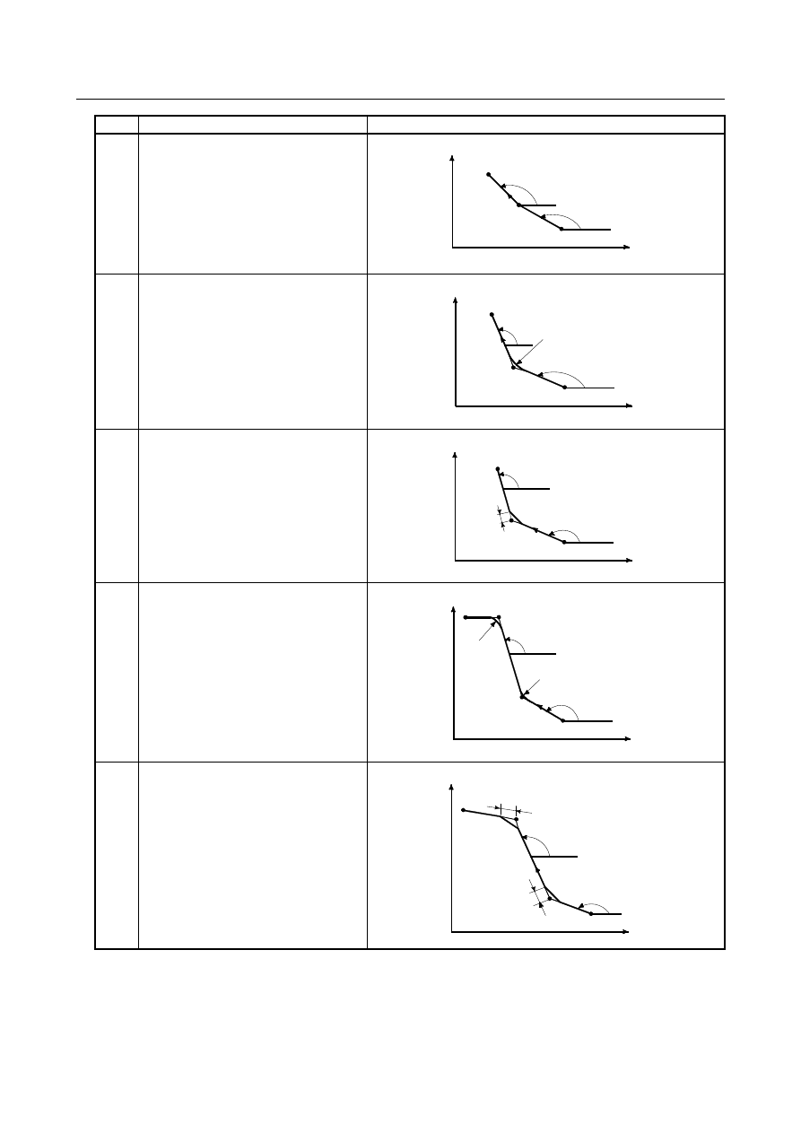
Commands 

Movement of tool 

,A1_ ; 
X3_ Z3_, A2_ ; 

(X1 , Z1)

(X3 , Z3)

(X2 , Z2)

X

Z

A1

A2


X2_ Z2_, R1_ ; 
X3_ Z3_ ; 
    or 
,A1_, R1_ ; 
X3_ Z3_, A2_ ; 

(X1 , Z1)

(X3 , Z3)

(X2 , Z2)

X

Z

A1

A2

R1


X2_ Z2_, C1_ ; 
X3_ Z3_ ; 
    or 
,A1_, C1_ ; 
X3_ Z3_, A2_ ; 

(X1 , Z1)

(X3 , Z3)

(X2 , Z2)

X

Z

A1

A2

C1


X2_ Z2_ , R1_ ; 
X3_ Z3_ , R2_ ; 
X4_ Z4_ ; 
    or 
,A1_, R1_ ; 
X3_ Z3_, A2_, R2_ ; 
X4_ Z4_ ; 

(X1 , Z1)

X

Z

A1

R1

A2

(X3 , Z3)

(X4 , Z4)

R2

(X2 , Z2)


X2_ Z2_ , C1_ ; 
X3_ Z3_ , C2_ ; 
X4_ Z4_ ; 
    or 
,A1_, R1_ ; 
X3_ Z3_, A2_, C2_ ; 
X4_ Z4_ ; 

(X1 , Z1)

(X3 , Z3)

(X2 , Z2)

X

Z

A1

A2

C1

(X4 , Z4)

C2


 PROGRAMMING 

 B-64604EN-1/01


- 138 - 

4. FUNCTIONS TO SIMPLIFY 

PROGRAMMING 


Commands 

Movement of tool 

X2_ Z2_ , R1_ ; 
X3_ Z3_ , C2_ ; 
X4_ Z4_ ; 
    or 
,A1_, R1_ ; 
X3_ Z3_, A2_, C2_ ; 
X4_ Z4_ ; 

(X1 , Z1)

(X3 , Z3)

(X2 , Z2)

X

Z

A2

(X4 , Z4)

C2

A1

R1


X2_ Z2_ , C1_ ; 
X3_ Z3_ , R2_ ; 
X4_ Z4_ ; 
    or 
,A1_, C1_ ; 
X3_ Z3_, A2_, R2_ ; 
X4_ Z4_ ; 

(X1 , Z1)

(X3 , Z3)

(X2 , Z2)

X

Z

A1

A2

C1

(X4 , Z4)

R2


Explanation 

A program for machining along the curve shown in Fig. 4.8 (a) is as follows : 


a

1

a

2

,A (a

1

) ,  C (c

1

) ; 

X (x

3

) Z (z

3

) , A (a

2

) , R  (r

2

) ; 

X (x

4

) Z (z

4

) ; 

(x

3

, z

3

(x

4

, z

4

a

3

c

1

(x

2

, z

2

(x

1

, z

1

Start point

X (x

2

) Z (z

2

) , C  (c

1

) ; 

X (x

3

) Z (z

3

) , R  (r

2

) ; 

X (x

4

) Z (z

4

) ; 

or 

r

2


+Z 

+X


Fig. 4.8 (a) Machining Drawing (example) 

 
For command a straight line, specify one or two out of X, Z, and A. 
If only one is specified, the straight line must be primarily defined by a command in the next block. 
To command the degree of a straight line or the value of chamfering or corner R, command with a comma 
(,) as follows : 

 ,A_ 
 ,C_ 
 ,R_ 

By specifying 1 to bit 4 (CCR) of parameter No.3405 on the system which does not use A or C as an axis 
name, the degree of a straight line or the value of chamfering or corner R can be commanded without a 
comma (,) as follows : 

 A_ 
 C_ 
 R_ 


 B-64604EN-1/01

 PROGRAMMING 


- 139 - 

4.FUNCTIONS TO SIMPLIFY 

PROGRAMMING

  - 

Command using a supplement 

When bit 5 (DDP) of parameter No. 3405 is set to 1, an angle can be specified using a supplement. 
There is the following relationship, assuming that the supplement is A' and the actual specified angle is A: 
 

A = 180 – A'


+Z

+X

A’

A


Fig. 4.8 (b) Supplement 


Limitation 

NOTE 

1  Direct drawing dimension programming commands are valid only during memory 

operation. 

2  The following G codes are not applicable to the same block as commanded by 

direct input of drawing dimensions or between blocks of direct input of drawing 
dimensions which define sequential figures. 

(a)  G codes other than G04 in group 00 
(b)  G codes other than G00, G01, and G33 in group 01 
(c)  G codes in group 10 (canned cycle for drilling) 
(d)  G codes in group 16 (plane selection) 
(e)  G22 and G23 

3  Corner R cannot be inserted into a threading block. 
4  When the chamfering and corner R function is enabled (bit 2 (CCR) of parameter 

No. 8134 is set to 1), both functions cannot be used simultaneously. When bit 0 
(CRD) of parameter No. 3453 is set to 1, direct drawing dimension programming 
is enabled. (At this time, chamfering and corner R are disabled.) 

5  When the end point of the previous block is determined in the next block 

according to sequential commands of direct drawing dimension programming 
during single block operation, the machine does not stop in the single block stop 
mode, but stop in the feed hold stop mode at the end point of the previous block. 

6  The angle allowance in calculating the point of intersection in the program below 

is 

±

1

°


(Because the travel distance to be obtained in this calculation is too large.) 

(a)  X_ ,A_ ; (If a value within 0

°±

1

°

 or 180

°±

1

°

 is specified for the angle 

instruction A, the alarm PS0057, “NO SOLUTION OF BLOCK END” occurs.) 

(b)  Z_ ,A_ ; (If a value within 90

°±

1

°

 or 270

°±

1

°

 is specified for the angle 

instruction A, the alarm PS0057 occurs.) 

7  An alarm PS0058, “END POINT NOT FOUND” occurs if the angle made by the 2 

lines is within 

±

1

°

 when calculating the point of intersection. 

8  Chamfering or corner R is ignored if the angle made by the 2 lines is within 

±

1

°

 PROGRAMMING 

 B-64604EN-1/01


- 140 - 

4. FUNCTIONS TO SIMPLIFY 

PROGRAMMING 

NOTE 

9  Both a dimensional command (absolute programming) and angle instruction 

must be specified in the block following a block in which only the angle 
instruction is specified. 

 (Example) 


N1 X_ ,A_ ,R_ ; 


N2 ,A_ ; 


N3 X_ Z_ ,A_ ; 


In addition to the dimensional command, angle command must be specified in 
block N3. If the angle command is not specified, alarm PS0056, “NO END 
POINT & ANGLE IN CHF/CNR” is issued. If the coordinates are not specified 
with an absolute programming, alarm PS0312, “ILLEGAL COMMAND IN 
DIRECT DRAWING DIMENSIONS PROGRAMMING” is issued. 

10  In the tool nose radius compensation mode, a block in which only the angle 

command is specified in direct drawing dimension programming is assumed to 
be a block with no move command. For details of compensation when sequential 
blocks with no move command are specified, see the explanation of tool nose 
radius compensation. 

11  If two or more blocks with no move command are specified between sequential 

commands of direct drawing dimension programming, alarm PS0312 is issued. 

12  When bit 4 (CCR) of parameter No. 3405 is set to 1, address A in the G76 

(multiple threading cycle) block specifies the tool nose angle. 


When A or C is used as an axis name, it cannot be used in the angle or 
chamfering command in direct drawing dimension programming. Use ,A_ or ,C_ 
(when bit 4 (CCR) of parameter No. 3405 is set to 0). 

13  In a multiple repetitive canned cycle, in blocks with sequence numbers between 

those specified at P and Q, a program using direct drawing dimension 
programming can be used. The block with the last sequence number specified at 
Q must not be an intermediate block of these specified blocks. 

14  If a minus value is commanded as a chamfering value / corner R value, alarm 

PS0055, “MISSING MOVE VALUE IN CHF/CNR” is issued. When bit 7 (CRC) of 
parameter No. 3458 is set to 1, alarm is not issued even if a minus value is 
commanded as a chamfering value / corner R value and a minus value is 
converted to a plus value. 


 B-64604EN-1/01

 PROGRAMMING 


- 141 - 

4.FUNCTIONS TO SIMPLIFY 

PROGRAMMING

Example 

22

°

180

30

×

45

°

10

°

R20

R6

X

φ

100

φ

300

Z

φ

60

(Diameter specification, metric input)

N001    G50 X0.0 Z0.0 ;
N002    G01 X60.0 ,A90.0 ,C1.0 F80 ;
N003    Z-30.0 ,A180.0 ,R6.0 ;
N004    X100.0 ,A90.0 ;
N005    ,A170.0 ,R20.0 ;
N006    X300.0 Z-180.0 ,A112.0 ,R15.0 ;
N007  Z-230.0 ,A180.0 ;

:
:

R15


5.COMPENSATION FUNCTION

 PROGRAMMING 

 B-64604EN-1/01


- 142 - 

COMPENSATION FUNCTION 

Chapter 5, "COMPENSATION FUNCTION", consists of the following sections: 
 
5.1 TOOL 

OFFSET.................................................................................................................................142 

5.2  OVERVIEW OF TOOL NOSE RADIUS COMPENSATION (G40-G42)......................................153 
5.3  OVERVIEW OF CUTTER COMPENSATION (G40-G42)............................................................165 
5.4  DETAILS OF CUTTER OR TOOL NOSE RADIUS COMPENSATION ......................................171 
5.5  VECTOR RETENTION (G38).........................................................................................................222 
5.6 CORNER 

CIRCULAR 

INTERPOLATION (G39) ..........................................................................223 

5.7  EXTENDED TOOL SELECTION ...................................................................................................225 
5.8  AUTOMATIC TOOL OFFSET (G36, G37) ....................................................................................228 
 

5.1 

TOOL OFFSET 

Tool offset is used to compensate for the difference when the tool actually used differs from the imagined 
tool used in programming (usually, standard tool). Tool nose moves on the programmed path by this 
compensation. 

Offset amount

on X axis

Standard tool

Actual tool

Offset amount

on Z axis


Fig. 5.1 (a) Tool offset 


5.1.1 

Tool Geometry Offset and Tool Wear Offset 

Tool geometry offset and tool wear offset are possible to divide the tool offset to the tool geometry offset 
for compensating the tool shape or tool mounting position and the tool wear offset for compensating the 
tool nose wear. The tool geometry offset value and tool wear offset value can be set individually. When 
these values are not distinguished from each other, the total of the values is set as the tool offset value. 
 

NOTE 


Tool geometry offset and tool wear offset are valid, when the bit 6 (NGW) of 
parameter No. 8136 is 0. 


 B-64604EN-1/01

 PROGRAMMING 

5.COMPENSATION FUNCTION


- 143 - 


Fig. 5.1.1 (a) If tool geometry offset and tool wear offset are distinguished   

from each other (left) and if they are not (right) 

 
Set the distance from tool nose to the point on the program ( tool nose of standard tool, or tool mounting 
position ) to a tool geometry offset value. 
 
Generally, a sign of tool wear offset value is the opposite to a sign of tool geometry offset value. In the 
example of the above figure, the geometry offset value is a positive and the wear offset value is a 
negative. 
 

5.1.2 

T Code for Tool Offset 

Format 

Select a tool with a numeric value after a T code. A part of the numeric value is used as a tool offset 
number for specifying data such as a tool offset value. The following selections can be made according to 
the specification method and parameter setting: 
 

Meaning of T code (*1) 

Bit 1 (LGN) of parameter No. 

5002=0 

Bit 1 (LGN) of parameter No. 

5002=1 

Parameter setting for specifying of 

offset No. (*2)


A tool wear offset number is specified 

using the lower one digit of a T code. 

T x x x x x x x    y 
xxxxxxx : Tool selection 

:  Tool wear and tool 

geometry offset 

T x x x x x x x    y 
xxxxxxx : Tool selection and tool 

geometry offset 

:  Tool wear offset 

When parameter No. 5028 is set to 1 

A tool wear offset number is specified 

using the lower two digits of a T code.

T x x x x x x    y y 
xxxxxx : Tool 

selection 

yy 

:  Tool wear and tool 

geometry offset 

T x x x x x x    y y 
xxxxxx : Tool 

selection and tool 

geometry offset 

yy 

:  Tool wear offset 

When parameter No. 5028 is set to 2 

A tool wear offset number is specified 

using the lower three digits of a T code.

T x x x x x  y y y 
xxxxx : 

Tool 

selection 

yyy : 

Tool 

wear 

and tool 

geometry offset 

T x x x x x  y y y 
xxxxx : 

Tool 

selection and tool 

geometry offset 

yyy 

:  Tool wear offset 

When parameter No. 5028 is set to 3 

 
*1  The maximum number of digits of a T code can be specified using parameter No. 3032. (1 to 8 

digits) 

*2  When parameter No. 5028 is set to 0, the number of digits of a T code used for offset number 

specification depends on the number of tool offsets. 
Example) 
When the number of tool offsets is 1 to 9: Lower one digit 
When the number of tool offsets is 10 to 99: Lower two digits 

Point on the program 

X axis geometry 
offset value 

X axis wear offset value 

Z axis geometry offset value 

Z axis wear offset value 

Offset amount 
on X axis 

Offset amount on Z axis 

Point on the program 

Imaginary tool 

Actual tool 

5.COMPENSATION FUNCTION

 PROGRAMMING 

 B-64604EN-1/01


- 144 - 

When the number of tool offsets is 100 to 999: Lower three digits 


5.1.3 

Tool Selection 

Tool selection is made by specifying the T code corresponding to the tool number. Refer to the machine 
tool builder's manual for the relationship between the tool selection number and the tool. 
 

5.1.4 

Offset Number 

Tool offset number has two meanings. It is specifies the offset distance corresponding to the number that 
is selected to begin the offset function. A tool offset number of 0 indicates that the offset amount is 0 and 
the offset is cancelled. 
 

5.1.5 

Offset 

Explanation 

 -  Offset methods 

Two methods are available to geometry offset and wear compensation, offset with tool movement and 
compensation with coordinate shift. Which offset method to select can be specified with bit 2 (LWT) and 
bit 4 (LGT) of parameter No. 5002. When tool geometry and wear compensation is disabled (bit 6 
(NGW) of parameter No. 8136 is set to 1), offset with tool movement is assumed unconditionally. 
 

Parameter 

Bit 6(NGW) of 
No.8136 

Compensation element 

LWT=0 
LGT=0 

LWT=1 
LGT=0 

LWT=0 
LGT=1 

LWT=1 
LGT=1 

Wear and geometry not 
distinguished 

Tool movement 

Wear compensation 

Tool movement Coordinate shift Tool movement  Coordinate shift

Geometry compensation 

Coordinate shift Coordinate shift Tool movement  Tool movement


  -  Offset with tool movement 

The tool path is offset by the X, Y, and Z tool offset values for the programmed path. The tool offset 
distance corresponding to the number specified by the T code is added to or subtracted from the end 
position of each programmed block. 
The vector with tool offset X, Y, and Z is called the offset vector. Offset is the same as the offset vector. 

This move command block
contains the offset command

with T code

Tool path after offset

Programmed path

Offset by tool offset X, Z (offset vector)


Offset operation with tool movement 


NOTE 

1  When G50 X_Z_T_ ; is specified, the tool is not moved. 
 

The coordinate system in which the coordinate value of the tool position (X,Z) is 
set. The tool position is obtained by subtracting the offset value corresponding to 
the tool offset number specified in the T code. 

 B-64604EN-1/01

 PROGRAMMING 

5.COMPENSATION FUNCTION


- 145 - 

NOTE 

2  The G codes in the 00 group other than G50 must not be specified in the same 

block as that containing a T code. If one of G28, G29, G30, and G53 is specified 
in the same block as that containing a T code, alarm PS0245, “T-CODE NOT 
ALLOWED IN THIS BLOCK”, is issued. 


  -  Offset with coordinate shift 

The workpiece coordinate system is shifted by the X, Y, and Z tool offset amounts. Namely, the offset 
amount corresponding to the number designated with the T code is added to or subtracted from the 
absolute coordinates. 


Programmed path after 
workpiece coordinate system  shift

The movement to this point is 
by an absolute  command. 

Tool path after offset

Programmed path before 
workpiece coordinate system  shift 

Offset amount by offset in 
X, Z axis (offset vector) 


Offset operation with coordinate shift 


  -  Starting and canceling offset by specifying a T code 

Specifying a tool offset number with a T code means to select the tool offset value corresponding to it and 
to start offset. Specifying 0 as a tool offset number means to cancel offset. 
For offset with tool movement, whether to start or cancel the offset can be specified with bit 6 (LWN) of 
parameter No. 5002. For compensation with coordinate shift, the offset is started and canceled when a T 
code is specified. For the cancellation of geometry compensation, its operation can be selected with bit 5 
(LGC) of parameter No. 5002. 
 

Offset method 

Bit 6 (LWM) of parameter No. 5002=0 

Bit 6 (LWM) of parameter No. 5002=1 

Tool movement 

When a T code is specified 

When an axial movement is specified 

Coordinate shift 

When a T code is specified 

(Note that geometry offset can be canceled only if bit 5 (LGC) of parameter No. 5002 = 1.)


  -  Canceling offset with reset 

Tool offset is canceled under one of the following conditions: 
 
<1>  The power to the CNC is turned off and turned back on 
<2>  The reset button on the MDI unit is pressed 
<3>  A reset signal is input from the machine to the CNC 
 
In cases <2> and <3> above, it is possible to select a cancel operation using bit 3 (LVC) of parameter No. 
5006 and bit 7 (TGC) of parameter No. 5003. 
 

Parameter 

Offset method 

LVC=0 

TGC=0 

LVC=1 

TGC=0 

LVC=0 

TGC=1 

LVC=1 

TGC=1 

Wear offset 

Tool 

movement  Geometry offset 

Not canceled.

Canceled. 

(When axial movement is 

specified) 

Not canceled. 

Canceled. 

(When axial movement 

is specified) 

Wear offset 

Not canceled.

Canceled. Not 

canceled. Canceled. 

Coordinate 

shift 

Geometry offset 

Not canceled.

Not canceled. 

Canceled. 

Canceled. 


5.COMPENSATION FUNCTION

 PROGRAMMING 

 B-64604EN-1/01


- 146 - 

Example 

N1 X60.0 Z50.0 T0202 ; 

Creates the offset vector corresponding to tool offset number 02. 

N2 Z100.0 ; 
N3 X200.0 Z150.0 T0200 ; 

Cancels the offset vector with offset number 0. 


N1

N2

Tool path after offset

Programmed tool path

N3


Limitation 

  -  Helical interpolation (G02, G03) 

Tool offset cannot be specified in a block in which helical interpolation is used. 
 

  -  Thread cutting (G32,G34,G35,G36) 

Tool offset cannot be specified in a block in which thread cutting is specified. If tool offset is specified, 
alarm PS0509, “TOOL OFFSET COMMAND IS NOT AVAILABLE”, is issued. 
 

  -  Coordinate system rotation (G68.1) 

Coordinate system rotation is executed on the command program first, followed by tool offset. 
 

  -  3-dimensional coordinate conversion (G68.1) 

If tool offset is used, tool offset with coordinate shift cannot be used. Offset with tool movement must be 
specified inside a nest of 3-dimensional coordinate conversion. At the beginning block of the 
3-dimensional coordinate conversion, tool does not move for a converted tool offset value. 
 
Example) G68.1 ... ; 
  T0101; 


    : 

  T0100; 


G69.1 ... ; 


  -  Workpiece coordinate system preset (G50.3) 

When the bit 7(WTC) of parameter No.1205 is 0, performing workpiece coordinate system preset causes 
tool offset with tool movement to be canceled; this does not cause tool offset with coordinate shift to be 
canceled. 
When the bit 7(WTC) of parameter No.1205 is 1, performing workpiece coordinate system preset does 
not cause neither tool position offset with tool movement nor tool position offset with coordinate shift to 
be canceled. 
 

 B-64604EN-1/01

 PROGRAMMING 

5.COMPENSATION FUNCTION


- 147 - 

  -  Machine coordinate system setting (G53), reference position return (G28), 

second, third, and fourth reference position return (G30), and manual 
reference position return 

Basically, before performing these commands or operations, cancel tool offset. These operations do not 
cause tool offset to be canceled. The following actions take place: 


When the command or operation is 

specified 

When the next axial movement command 

is specified 

Tool movement 

The tool offset value is temporarily 
canceled. 

The tool offset value is reflected. 

Coordinate shift 

Coordinates with the tool offset value 
reflected are assumed. 

Coordinates with the tool offset value 
reflected are assumed. 


  -  Offset command in the coordinate system rotation or programmable mirror 

image mode 

If tool offset is specified when offset with coordinate system shift is enabled (when bit 2 (LWT) of 
parameter No. 5002 is set to 1 or bit 4 (LGT) of parameter No. 5002 is set to 0) in the coordinate system 
rotation or programmable mirror image mode, alarm PS0509 is issued. The same alarm is issued when bit 
6 (EVO) of parameter No. 5001 is set to 1 and the offset amount is changed. 
 

Auxiliary function output in moving axis (G50.9)   

The alarm PS5330, “G50.9 FORMAT ERROR” is issued when a T-code and auxiliary function output in 
moving axis (G50.9) are specified in the same block. 
 

Programmable parameter input (G10)   

The alarm PS1144, “G10 FORMAT ERROR” is issued when a T-code is specified during programmable 
parameter input. 
 

5.1.6 

Y-Axis Offset 

Overview 

When the Y axis, one of the basic three axes, is used with a lathe system, this function performs Y axis 
offset. 
If the tool geometry and wear offset options are valid (the bit 6 (NGW) of parameter No. 8136 is 0), the 
both tool geometry offset and tool wear offset are effective to Y-axis offset. 
 

NOTE 


When bit 1 (YOF) of parameter No.8132 is 1, this function can be used. 


Explanation 

Y axis offset results in the same operation as tool offset. For an explanation of the operation, related 
parameters, and the like, refer to the item “Tool Offset.” 
 

5.1.6.1 

Support of arbitrary axes for Y axis offset 

Overview 

In a lath system, Y axis offset has been usable with the basic three axes only. This function enables Y axis 
offset to be used with arbitrary axes other than the Y axis, which is one of the basic three axes. 
 

5.COMPENSATION FUNCTION

 PROGRAMMING 

 B-64604EN-1/01


- 148 - 

5.1.7 

2nd Geometry Tool Offset 

Overview 

To compensate for a difference in tool attachment position or selection position, this function adds second 
geometry tool offset to the X axis, Y axis, and Z axis with all paths. 
In contrast to this offset, the ordinary tool geometry offset is called the first geometry tool offset. 
It is possible to apply a tool offset value (tool wear offset + tool geometry offset) in the reverse direction, 
using an appropriate signal. 
This function may be used if the offset value differs even with a single tool for a mechanical reason 
depending on the mounting position (inside/outside) or the selected position (right/left). 
 

NOTE 

1  This function is an optional function. 

To use this function, this option and "Tool geometry offset and Tool wear offset" 
are required. "Tool geometry offset and Tool wear offset" can be used, when bit 
6 (NGW) of parameter No.8136 is 0. 

2  When the "Y-axis offset" is enabled (bit 1 (YOF) of parameter No.8132 is 1), the 

"2nd Geometry tool offset" for Y axis can be used. 


Format 

 If bit 1 (LGN) of parameter No. 5002 = 1 


T

First geometry tool offset number or

first + second geometry tool offset numbers

;

Tool wear offset number

(M code that enables second geometry tool offset) ;

M


 If bit 1 (LGN) of parameter No. 5002 = 0 


Tool wear offset number + first geometry tool offset 
number or wear + first + second geometry tool offset 
numbers 

(M code that enables second geometry tool offset) ;


Explanation 

 -  Specification method 

Offset using the second geometry tool offset is performed with a program command. 
Specify the second geometry tool offset with a T code command, and using the second geometry tool 
offset signal G2SLC, specify whether to set the offset value of the specified tool geometry offset number 
to the first geometry tool offset only or to the first geometry tool offset plus the second geometry tool 
offset. If using the first geometry tool offset plus the second geometry tool offset, specify the axis to 
which the second geometry tool offset is to be applied, using the appropriate one of the second geometry 
tool offset axis select signal G2X, G2Z, and G2Y. 
 
Generally, before a T code command, specify the M code to enable the second geometry tool offset. For 
details, refer to the manual supplied by the machine tool builder. The same number as the first geometry 
tool offset number is always selected as the second geometry tool offset number. 
During execution, the tool offset value for each axis is either of the following: 


First geometry tool offset value + tool wear offset value 


First geometry tool offset value + second geometry tool offset value + tool wear offset value 


 B-64604EN-1/01

 PROGRAMMING 

5.COMPENSATION FUNCTION


- 149 - 

Example) 


The code is a 4-digit code. (The number of digits of a T code is specified with parameter No. 3032.) 


The offset type is tool movement (bit 4 (LGT) of parameter No. 5002 = 1). 


The lower two digits of the T code is the tool geometry offset number (parameter No. 5028 = 2). 


Offset is performed when the T code block is executed (bit 6 (LWM) of parameter No. 5002 = 0). 


The X axis data for first geometry tool offset number 1 is 1.000. 


The X axis data for second geometry tool offset number 1 is 10.000. 


The tool geometry offset number is specified with the tool selection number (bit 1 (LGN) of 
parameter No. 5002 = 1). 


Signals G2SLC = '1', G2X = '1', and G2Z = G2Y = '0' 


If T0102 is specified under the above conditions, the upper two digits 01 of the T code cause the first 
and second geometry tool offset numbers 1 to be selected, so that the absolute and machine 
coordinates will be 11.000 on the X axis only. 


 -  Offset data 

The data for the second geometry tool offset can be set for each path. The number of items of the data can 
be set with parameter No. 5024. The data remains stored even after the power is turned off. 
If the data is to be made common to paths, use the common memory between each path. 
 

Example 

O (workpiece origin)

Z

X

T01/Z (first) : 5

T11 to T16/X

  (second) : 120

T16/Z (second) : - 190

T13/Z (second) : - 70

T12/Z (second) : - 30

T01

T12

T13

T16

T11

-

-

-

-

T11/Z (second) : 10

O

X

Z

T01/X (first) : 20

First path (standard turret)

Second path

(linear turret)


Fig. 5.1.7 (a) Example of the application of the second geometry tool offset 


5.COMPENSATION FUNCTION

 PROGRAMMING 

 B-64604EN-1/01


- 150 - 

In the machine configuration shown in the Fig. 5.1.7 (a), for the offset data for the tool mounted to the 
first path (standard turret), set the offset data of the tool itself as the first geometry tool offset data. (The 
second geometry tool offset data is 0.) For the offset data for the tool mounted to the second path (linear 
turret), set the offset data of the tool itself as the first geometry tool offset data and the offset data from 
the workpiece origin at the mounting position as the second geometry tool offset data. Usually, the offset 
data of the tool itself is measured separately from the offset data at the mounting position, these data can 
be set separately by using the second geometry tool offset. 

First geometry tool offset 

Second geometry tool offset 

No. 

X axis 

Z axis 

No. 

X axis 

Z axis 

01 20.000 5.000 01 0.000  0.000 

: :  : : :  : 

10 25.000 8.000 10 0.000  0.000 
11 -20.000  5.000  11 120.000 10.000 
12 -10.000  3.000  12 120.000 -30.000 
13 -15.000  0.000  13 120.000 -70.000 

: :  : : :  : 

16 -18.000  7.000  16 120.000 -190.000 


5.1.8 

4th/5th Axis Offset 

Overview 

This function enables tool offset for the 4th axis and 5th axis following the basic three axes (X, Y, and Z 
axes). As with tool offsets based on the basic three axes (X, Y, and Z axes), 128 sets of 4th/5th axis tool 
offsets are available. By setting bit 6(NGW) of parameter No.8136 to 0, tool geometry offset and tool 
wear offset are enabled. Moreover, the number of sets can be increased from 128 to 200 by specifying an 
option. 
A tool offset value can be applied to arbitrary axes by setting an axis number (1 to the maximum number 
of controlled axes) to be used for 4th axis offset in parameter No. 5044 and setting an axis number (1 to 
the maximum number of controlled axes) to be used for 5th axis offset in parameter No. 5045. By setting 
bit 1 (NO5) of parameter No. 11400 to 1, 5th axis offset is enabled. 
If the same axis as used with the Y axis offset function is specified, however, a Y axis offset value is 
applied to the specified axis, and a 4th axis offset value or 5th axis offset value is invalidated. 
Tool offset values can be input through an I/O device. 
 

NOTE 


This function is an optional function. 


Explanation 

The operation of 4th/5th axis offset is the same as the operation of tool offset. For the operation, see 
Section 5.1, "TOOL OFFSET". 


  Setting of tool offset values with the G10 command 

By programming, 4th/5th axis offset values can be input. 
 

 B-64604EN-1/01

 PROGRAMMING 

5.COMPENSATION FUNCTION


- 151 - 

Format 

G10 P_ X_ Y_ Z_ R_ Q_ E_ F_ ; 
or 
G10 P_ U_ V_ W_ C_ Q_ E_ F_; 

P : Offset number 


: Specifies a workpiece coordinate system shift value. 

1 to 200   

: Specifies a tool wear offset value. 

10000+(1 to 200)   : Specifies a tool geometry offset value, with a number (1 to 200)   


  representing an offset number. 

X  : X axis offset value (absolute) 
Y  : Y axis offset value (absolute) 
Z  : Z axis offset value (absolute) 
U  : X axis offset value (incremental) 
V  : Y axis offset value (incremental) 
W : Z axis offset value (incremental) 
R  : Tool nose radius compensation value (absolute) 
C  : Tool nose radius compensation value (incremental) 
Q  : Virtual tool nose number 
E  : 4th axis offset value (absolute) 
F  : 5th axis offset value (absolute) 


 -  Explanation 

As in the G10 format above, address E for inputting a 4th axis offset value and address F for inputting a 
5th axis offset value allow absolute values only to be input. 
 

NOTE 

1  When compared with the conventional G10 format for changing tool offset 

values, address E for specifying a 4th axis offset value and address F for 
specifying a 5th axis offset value are newly added in the format above. 

2  When a program based on the G10 format above is executed, only those offset 

values that correspond to programmed axis addresses and offset numbers are 
rewritten. 


  -  Address name changing of format 

When bit 2 (OFS) of parameter No.11403 is set to 1, the specification address in "Y-axis offset and 
4th/5th axis offset" can use address name 'A' or 'B' instead of default specification addresses 'Y', 'E' and 
'F'. 
 
Example) When parameters are set to follow, the command address 'A' and 'B' are used for setting of a 

tool offset. 

Parameter No.5044 is set to 4 (4th axis offset is the 4th axis) 

Parameter No.5045 is set to 5 (5th


axis offset is the 5th axis) 

Parameter No.1020 (4th


axis ,5th


axis) = 65, 66 (Address name of 4th /5th


axis offset is 'A' and 

'B') 

Bit 2 (OFN) of No.11403 is set to 1 (Address depend on parameter No.1020) 


5.COMPENSATION FUNCTION

 PROGRAMMING 

 B-64604EN-1/01


- 152 - 


G10 P01 X_ Z_ A_ B_ 
G10 P02 X_ Z_ A_ B_ 
... 
G10 P__ X_ Z_ A_ B_ 

A_ : 

Tool compensation data (4th axis offset value in the example).   

B_ : 

Tool compensation data (5th axis offset value in the example).   

The other addresses are the same as for the tool compensation amount. 


NOTE 

1  The axis name that can be used as a specification address is only 'A', and 'B'. 
 

If specification address 'A' or 'B' is used, the address 'V' (incremental command 
of Y-axis offset) cannot be used. 

2  If the either of following is set, the default specification addresses 'Y', 'E', and 'F' 

are used. 
-  Parameter No.1020 is set to axis name other than 'A(65)' or 'B(66)'. 
-  An extended axis name is used. 

3  When bit 2 (OFN) of parameter No.11403 is set to 1, conventional offset data 

cannot be read. If conventional offset data is read, set 0 to bit 2 (OFN) of 
parameter No.11403. 


Limitation 

1.  This function is a software option. 
2.  This function supports the common memory between each path. 
3.  This function does not support direct input/counter input of tool offset values. 
4.  This function does not support offset value writing using a custom macro variable. 
5.  This function does not support the PMC window function. 
 

However, this function supports writing/reading of 4th/5th axis offset values to and from the C 
Language Executor. 

6.  This function does not support external data input. So, no 4th/5th axis offset value can be modified 

with a PMC ladder. 

7.  This function does not support the second geometry tool offset function. 
8.  This function does not support the tool management function. 
9.  This function does not support the wrong operation prevention function. 


Content      ..     8      9      10      11     ..