FANUC Series 0i-MODEL F. For Lathe System OPERATOR'S MANUAL (B-64604EN-1/01) - page 8
 

  Index      Manuals     FANUC Series 0i-MODEL F. For Lathe System OPERATOR'S MANUAL (B-64604EN-1/01)


Search            copyright infringement  


Content      ..     6      7      8      9     ..


FANUC Series 0i-MODEL F. For Lathe System OPERATOR'S MANUAL (B-64604EN-1/01) - page 8


 B-64604EN-1/01

 PROGRAMMING 


- 105 - 

4.FUNCTIONS TO SIMPLIFY 

PROGRAMMING


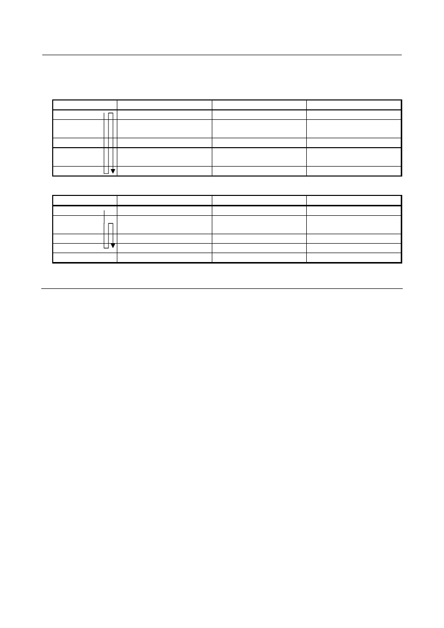
Manual Handle Retrace 

This function is available in the check mode of manual handle retrace. 

In case of canceling of canned cycle for drilling 

 Forward Backward 

Re-forward 

G00 X_ Z_ ; 


G83 Z_ C_ F_ ; 

Parameter No.3740 is 
available. 

Not waiting time. 

Parameter No.3740 is 
available. 

C_ ; 

Not waiting time. 

Not waiting time. 

Not waiting time. 

C_ ; 

Not waiting time. 

Parameter No.3740 is 
available. 

Not waiting time. 

G80 ; 


In case of not canceling of canned cycle for drilling 


Forward Backward 

Re-forward 

G00 X_ Z_ ; 


G83 Z_ C_ F_ ; 

Parameter No.3740 is 
available. 

Not waiting time. 

Not waiting time. 

C_ ; 

Not waiting time. 

Not waiting time. 

Not waiting time. 

C_ ; 

Not waiting time. 

Not waiting time. 

Not waiting time. 

G80 


4.3.7 

Precautions to be Taken by Operator 

  - 

Reset and emergency stop 

Even when the controller is stopped by resetting or emergency stop in the course of drilling cycle, the 
drilling mode and drilling data are saved; with this mind, therefore, restart operation. 
 

 -  Single block 

When drilling cycle is performed with a single block, the operation stops at the end points of operations 1, 
2, 6 in Fig. 4.3 (a). 
Consequently, it follows that operation is started up 3 times to drill one hole. The operation stops at the 
end points of operations 1, 2 with the feed hold lamp ON. If there is a remaining repetitive count at the 
end of operation 6, the operation is stopped by feed hold. If there is no remaining repetitive count, the 
operation is stopped in the single block stop state. 
 

 -  Feed hold 

When "Feed Hold" is applied between operations 3 and 5 by G84/G88, the feed hold lamp lights up 
immediately if the feed hold is applied again to operation 6. 
 

 -  Override 

During operation with G84 and G88, the feedrate override is 100%. 
 

 PROGRAMMING 

 B-64604EN-1/01


- 106 - 

4. FUNCTIONS TO SIMPLIFY 

PROGRAMMING 

4.4 

RIGID TAPPING 

Front face tapping cycles (G84) and side face tapping cycles (G88) can be performed either in 
conventional mode or rigid mode. 
In conventional mode, the spindle is rotated or stopped, in synchronization with the motion along the 
tapping axis according to miscellaneous functions M03 (spindle CW rotation), M04 (spindle CCW 
rotation), and M05 (spindle stop). 
In rigid mode, the spindle motor is controlled in the same way as a control motor, by the application of 
compensation to both motion along the tapping axis and that of the spindle. 
For rigid tapping, each turn of the spindle corresponds to a certain amount of feed (screw lead) along the 
spindle axis. This also applies to acceleration/deceleration. This means that rigid tapping does not demand 
the use of float tappers as in the case of conventional tapping, thus enabling high-speed, high-precision 
tapping. 
When the multi-spindle control function is valid (the bit 3 (MSP) of parameter No. 8133 is 1), the second 
or third spindles can be used for rigid tapping. 
 

NOTE 


When bit 3 (NRG) of parameter No.8135 is 0, this function can be used. 


 B-64604EN-1/01

 PROGRAMMING 


- 107 - 

4.FUNCTIONS TO SIMPLIFY 

PROGRAMMING

4.4.1 

Front Face Rigid Tapping Cycle (G84) / Side Face Rigid 
Tapping Cycle (G88) 

Controlling the spindle motor in the same way as a servo motor in rigid mode enables high-speed tapping. 
 

Format 


G84 X (U)_ C (H)_ Z (W)_ R_ P_ F_ K_ M_ ;

or 

G88 Z (W)_ C (H)_ X (U)_ R_ P_ F_ K_ M_ ;

X_ C_ or Z_ C_    :  Hole position data 

Z_ or X_   

:  The distance from point R to the bottom of the hole 

R_  :  The distance from the initial level to point R level 

P_  :  Dwell time at the bottom of a hole 

F_ : Cutting 

feedrate 

K_  :  Number of repeats (When it is needed.) 

Number of repeats is specified by address L_, in case of bit 1 (FCV) 

of parameter No.0001 = 1. 

M_  :  M code for C-axis clamp (when it is needed.) 

G84 or G88 (G98 mode)

G84 or G88 (G99 mode) 

Initial level

Point R 

Spindle stop

Spindle CW

Point Z

Point R  level

Operation 2 

Operation 1 

Operation 6

Operation 3 

Operation 4

Operation 5

Spindle stop 

Spindle CCW

Point R

Point Z 

P

Point R  level 

Spindle stop

Spindle CCW 

Spindle stop 

Spindle stop 

Spindle stop

P2

P2 

Spindle CW


P2 performs dwelling of C-axis unclamp. (The dwell time is set in parameter No. 5111.) 
 
In front face rigid tapping (G84), the plane first axis is used as the drilling axis and the other axes are used 
as positioning axes. 

Bit 0 (RTX) of parameter No. 5209 

Plane selection 

Drilling axis 

G17: Xp-Yp plane 

Xp 

G18: Zp-Xp plane 

Zp 

G19: Yp-Zp plane 

Yp 

1  

Zp 

 
Xp: X axis or its parallel axis 
Yp: Y axis or its parallel axis 
Zp: Z axis or its parallel axis 
 

 PROGRAMMING 

 B-64604EN-1/01


- 108 - 

4. FUNCTIONS TO SIMPLIFY 

PROGRAMMING 

In side face rigid tapping (G88), the plane first axis is used as the drilling axis and the other axes are used 
as positioning axes. 

Bit 0 (RTX) of parameter No. 5209 

Plane selection 

Drilling axis 

G17: Xp-Yp plane 

Yp 

G18: Zp-Xp plane 

Xp 

G19: Yp-Zp plane 

Zp 

1  

Xp 

 
Xp: X axis or its parallel axis 
Yp: Y axis or its parallel axis 
Zp: Z axis or its parallel axis 


(Series 10/11 format)


G84.2 X (U)_ C (H)_ Z (W)_ R_ P_ F_ L_ S_ ;


X_ C_ or Z_ C_    :  Hole position data 

Z_ or X_   

:  The distance from point R to the bottom of the hole 

R_  :  The distance from the initial level to point R level 

P_  :  Dwell time at the bottom of a hole 

F_ : Cutting 

feedrate 

L_  :  Number of repeats (When it is needed.) 

S_  :  Spindle speed 

C-axis clamp cannot be performed during specification of the Series 10/11

format. 

G84.2 (G98 mode)

G84.2 (G99 mode) 

Initial level 

Point R 

Spindle stop

Spindle CW 

Point Z

Point R level

Operation 2

Operation 1 

Operation 6

Operation 3 

Operation 4

Operation 5

Spindle stop 

Spindle 

Point R

Spindle CW

Point Z 

P

Point R level 

Spindle stop

Spindle CCW 

Spindle stop 

Spindle stop

Spindle stop 


A G code cannot discriminate between front face tapping cycle and side face tapping cycle using Series 
10/11 format commands(G84.2). The drilling axis is determined by plane selection (G17/G18/G19). 
Specify the plane selection that becomes equivalent to front face tapping cycle or side face tapping cycle 
as appropriate. (When FXY (bit 0 of parameter No. 5101) is 0, the Z-axis is used as the drilling axis. 
When FXY is 1, plane selection is as Table 4.4.1 (a).) 
 

Table 4.4.1 (a) 

Plane selection 

Drilling axis 

G17: Xp-Yp plane 

Zp 

G18: Zp-Xp plane 

Yp 

G19: Yp-Zp plane 

Xp 

Xp: X axis or its parallel axis 
Yp: Y axis or its parallel axis 

 B-64604EN-1/01

 PROGRAMMING 


- 109 - 

4.FUNCTIONS TO SIMPLIFY 

PROGRAMMING

Zp: Z axis or its parallel axis 
 
Thus, the rigid tapping mode can be specified in two formats: G84/G88(FS0i-F format) and 
G84.2(FS10/11 format). A usable format can be selected by parameter setting. 

Parameter 

Bit 1 (FCV) of 

parameter No. 0001 

Bit 3 (F16) of 

parameter No. 5102 

Executable command format 

0 - 

FS0i-F format only (The number of repeats is specified using address 
K.) 

1 0 

FS10/11 format or   
FS0i-F format (The number of repeats is specified using address L.) 

FS0i-F format only (The number of repeats is specified using address L.)


Explanation 

Once positioning for the X-axis (G84) or Z-axis (G88) has been completed, the spindle is moved, by 
rapid traverse, to point R. Tapping is performed from point R to point Z, after which the spindle stops and 
observes a dwell time. Then, the spindle starts reverse rotation, retracts to point R, stops rotating, then 
moves to the initial level by rapid traverse. 
During tapping, the feedrate override and spindle override are assumed to be 100%. For retraction 
(operation 5), however, a fixed override of up to 2000% can be applied by setting bit 4 (DOV) of 
parameter No. 5200, bit 3 (OVU) of parameter No. 5201, and parameter No. 5211. 
 

 -  Rigid mode 

Rigid mode can be specified by applying any of the following methods: 
(1)  Specifying M29S***** before a tapping block   
(2)  Specifying M29S***** within a tapping block 
(3)  Handling G84 or G88 as a G code for rigid tapping (Set bit 0 (G84) of parameter No. 5200 to 1.) 
 

 -  Thread lead 

In feed per minute mode, the feedrate divided by the spindle speed is equal to the thread lead. In feed per 
rotation mode, the feedrate is equal to the thread lead. 
 

  - 

Series 10/11 format command 

Rigid tapping can be performed using Series 10/11 format commands. 
 

 -  Acceleration/deceleration after interpolation 

Linear or bell-shaped acceleration/deceleration can be applied. 
Details are given later. 
 

 -  Look-ahead acceleration/deceleration before interpolation 

Look-ahead acceleration/deceleration before interpolation is invalid. 
 

 -  Override 

Various types of override functions are invalid. The following override functions can be enabled by 
setting corresponding parameters: 
(1) Extraction 

override 

(2) Override 

signal 


 -  Dry run 

Dry run can be executed also in G84 (G88). When dry run is executed at the feedrate for the drilling axis 
in G84 (G88), tapping is performed according to the feedrate. Note that the spindle speed becomes faster 
at a higher dry run feedrate. 
 

 PROGRAMMING 

 B-64604EN-1/01


- 110 - 

4. FUNCTIONS TO SIMPLIFY 

PROGRAMMING 

 -  Machine lock 

Machine lock can be executed also in G84 (G88). 
When G84 (G88) is executed in the machine lock state, the tool does not move along the drilling axis. 
Therefore, the spindle does not also rotate. 
 

 -  Reset 

When a reset is performed during rigid tapping, the rigid tapping mode is canceled and the spindle motor 
enters the normal mode. Note that the G84 (G88) mode is not canceled in this case when bit 6 (CLR) of 
parameter No. 3402 is set. 
 

 -  Interlock 

Interlock can also be applied in G84 (G88). 
 

  - 

Feed hold and single block 

When bit 6 (FHD) of parameter No. 5200 is set to 0, feed hold and single block are invalid in the G84 
(G88) mode. When this bit is set to 1, they are valid. 
 

 -  Manual feed 

For rigid tapping by manual handle feed, see the section "Rigid Tapping by Manual Handle." 
With other manual operations, rigid tapping cannot be performed. 
 

 -  Backlash compensation 

In the rigid tapping mode, backlash compensation is applied to compensate the lost motion when the 
spindle rotates clockwise or counterclockwise. Set the amount of backlash in parameters Nos. 5321 to 
5324. 
Along the drilling axis, backlash compensation has been applied. 
 

  - 

C-axis clamp, C-axis unclamp 

It is possible to specify an M code for mechanically fixing or releasing the C-axis during rigid tapping. 
Adding an M code for clamp to the G84 (G88) block outputs both M codes. Descriptions of timing are 
provided later. 
An M code for clamp is set in parameter No. 5110. An M code for unclamp is assumed as Table 4.4.1 (b) 
depending on the setting of parameter No. 5110. 
 

Table 4.4.1 (b) 

Parameter No.5110 

0 Non-0 

No M codes are output. 

The setting of parameter No.5110 + 1 is assumed. 


Limitation 

 -  Axis switching 

Before the drilling axis can be changed, the canned cycle must be canceled. If the drilling axis is changed 
in rigid mode, alarm PS0206, “CAN NOT CHANGE PLANE (RIGID TAP)” is issued. 
 

 -  S commands 

When a value exceeding the maximum rotation speed for the gear being used is specified, alarm PS0200, 
“ILLEGAL S CODE COMMAND” is issued. If such a command that the number of pulses of 8 msec is 
32768 or more on the detection unit level or the number of pulses of 8 msec is 32768 or more for a serial 
spindle is specified, alarm PS0202, “POSITION LSI OVERFLOW” is issued. 


<Example> 
For a built-in motor equipped with a detector having a resolution of 4095 pulses per rotation, the 
maximum spindle speed during rigid tapping is as follows: 

 B-64604EN-1/01

 PROGRAMMING 


- 111 - 

4.FUNCTIONS TO SIMPLIFY 

PROGRAMMING

(4095

×

1000

÷

8

×

60)

÷

4095=7500 (min

-1

For a serial spindle 
 (32767

×

1000

÷

8

×

60)

÷

4095=60012(min

-1

) [Note: Ideal value] 


 -  F commands 

Specifying a value larger than the upper limit for cutting feed will cause alarm PS0201, “FEEDRATE 

NOT FOUND IN RIGID TAP” to be issued. 


  - 

Unit of F command 


Metric input 

Inch input 

Remarks 

G98 

1mm/min 

0.01inch/min 

Decimal point programming allowed 

G99 

0.01mm/rev 

0.0001inch/rev 

Decimal point programming allowed 


 -  M29 

If an S command and axis movement are specified between M29 and G84, alarm PS0203, “PROGRAM 
MISS AT RIGID TAPPING” is issued. If M29 is specified in a tapping cycle, alarm PS0204, “ILLEGAL 
AXIS OPERATION” is issued. 
 

 -  P 

Specify P in a block that performs drilling. If P is specified in a non-drilling block, it is not stored as 
modal data. 
 

 -  Cancel 

Do not specify a G code of the 01 group (G00 to G03) and G84 in a single block. Otherwise, G84 will be 
canceled. 
 

 -  Tool offset 

In the canned cycle mode, tool offsets are ignored. 
 

 -  Program restart 

A program cannot be restarted during rigid tapping. 
 

 -  R 

The value of R must be specified in a block which performs drilling. If the value is specified in a block 
which does not perform drilling, it is not stored as modal data. 
 

 -  Subprogram call 

In the canned cycle mode, specify the subprogram call command M98P_ in an independent block. 
 

Constant surface speed control 

If rigid tapping is commanded during constant surface speed control, alarm (PS0200), ”ILLEGAL S 
CODE COMMAND” is issued. Command rigid tapping after canceling constant surface speed control. 
 

Example 

Tapping axis feedrate: 1000 mm/min 
Spindle speed: 1000 min

-1


Screw lead: 1.0 mm 
<Programming for feed per minute> 
 

G98 ; 

...................................... Command for feed per minute 


G00 X100.0 ;................................. Positioning 


M29 S1000;................................... Command for specifying rigid mode   


G84 Z-100.0 R-20.0 F1000 ;......... Rigid tapping   

<Programming for feed per rotation> 

 PROGRAMMING 

 B-64604EN-1/01


- 112 - 

4. FUNCTIONS TO SIMPLIFY 

PROGRAMMING 


G99 ; 

...................................... Command for feed per rotation 


G00 X100.0 ;................................. Positioning 


M29 S1000 ;.................................. Command for specifying rigid mode   


G84 Z-100.0 R-20.0 F1.0 ;............ Rigid tapping 


4.4.2 

Peck Rigid Tapping Cycle (G84 or G88) 

Tapping a deep hole in rigid tapping mode may be difficult due to chips sticking to the tool or increased 
cutting resistance. In such cases, the peck rigid tapping cycle is useful. 
In this cycle, cutting is performed several times until the bottom of the hole is reached. Two peck tapping 
cycles are available: High-speed peck tapping cycle and standard peck tapping cycle. These cycles are 
selected using the bit 5 (PCP) of parameter No. 5200. 
 

Format 

When rigid tapping is specified with G84 (G88) if bit 5 (PCP) of parameter No. 5200 = 0, high-speed 
peck rigid tapping is assumed. 

Point R 

level 

Point Z 

Point R

q

q

q

M

α

(1)

(2) 

Spindle CCW

Spindle stop

M(

α

+1) 

P2 

Spindle stop 
Spindle CCW 

Spindle stop 
Spindle CW 

Spindle CW

P1 

Spindle stop 

(3) 

Spindle stop 

G84 or G88(G98 mode) 

G84 or G88(G99 mode) 

G84 X(U)_ C(H)_Z(W)_ R_ P_ Q_ F_ K_ M_ ;
or 
G88 Z(W)_ C(H)_X(U)_ R_ P_ Q_ F_ K_ M_ ; 

X_ C_ or Z_ C_ : Hole position data 

Z_ or X_ : The distance from point R to the bottom of the hole 

R_      : The distance from the initial level to point R level 

P_      : Dwell time at the bottom of the hole 

Q_      : Depth of cut for each cutting feed 

F_   : The cutting feedrate 

K_      : Number of repeats (when it is needed.) 

M_      : M code for C-axis clamp (when it is needed.) 

- High-speed peck rigid tapping cycle 

In the first cutting from point R, perform 
cutting by depth "q" specified by address Q 
while rotating the spindle in the forward 
direction (operation <1>). 
Then, perform returning by the amount 
specified by parameter No. 5213 while 
rotating the spindle in the reverse direction 
(operation <2>). 
Then, perform tapping by (d+q) while 
rotating the spindle in the forward direction 
(operation <3>). 
 
Repeat operations <2> and <3> until the 
bottom of the hole is reached. 
 
The cutting speed and rigid tapping time 
constant are used for operations <1> and 
<3>. 
For operation <2> and travel from the 
bottom of the hole (point Z) to point R, rigid 
tapping extract override is enabled and the 
rigid tapping extract time constant is used. 

d = Amount of
return 

Spindle stop

(3)

Point R 

level

P1

Spindle stop

Spindle CW

Point R

Point Z

q

q

q

M

α

(1)

d

(2)

d

Initial level

Spindle CCW

Spindle stop

M(

α

+1) 

P2 

Spindle stop 
Spindle CCW

Spindle stop
Spindle CW


When rigid tapping is specified with G84 (G88) if bit 5 (PCP) of parameter No. 5200 = 1, peck rigid 
tapping is assumed. 

 B-64604EN-1/01

 PROGRAMMING 


- 113 - 

4.FUNCTIONS TO SIMPLIFY 

PROGRAMMING

G84 or G88(G98 mode) 

G84 or G88(G99 mode) 

G84 X(U)_ C(H)_Z(W)_ R_ P_ Q_ F_ K_ M_ ;
or 
G88 Z(W)_ C(H)_X(U)_ R_ P_ Q_ F_ K_ M_ ; 

X_ C_ or Z_ C_ : Hole position data 
Z_ or X_ : The distance from point R to the bottom of the hole 

R_      : The distance from the initial level to point R level 

P_      : Dwell time at the bottom of the hole 
Q_      : Depth of cut for each cutting feed 

F_   : The cutting feedrate 

K_      : Number of repeats (when it is needed.) 

d = Cutting start distance 

M_      : M code for C-axis clamp (when it is needed.) 

- Peck rigid tapping cycle 

In the first cutting from point R, perform 
cutting by depth "q" specified by address Q 
while rotating the spindle in the forward 
direction (operation <1>). 
Then, return to point R by rotating the 
spindle in the reverse direction (operation 
<2>). 
Then, rotate the spindle in the forward 
direction and perform cutting to the position 
indicated by [(Position to which cutting was 
performed previously) - (Cutting start 
distance set in parameter No. 5213)] as 
movement to the cutting start point 
(operation <3>). 
Continue cutting by (d+q) (operation <4>). 
 
Repeat operations <2> to <4> until the 
bottom of the hole is reached. 
 
The cutting speed and rigid tapping time 
constant are used for operations <1> and 
<4>. 
For operations <2>, <3>, and travel from 
the bottom of the hole (point Z) to point R, 
rigid tapping extract override is enabled 
and the rigid tapping extract time constant 
is used.

Spindle stop

Point Z

q

q

M

α

(1)

d

(2)

Initial level

Spindle stop

M(

α

+1) 

P2 

Point R 

level

Point R


(3)

(4)

d

d

q

P1

Spindle stop

Spindle CW 

Spindle CCW

Spindle stop 
Spindle CCW

Spindle stop 
Spindle CW

Point Z 

q

q

M

α

(1)

d

(2) 

Spindle stop

M(

α

+1) 

P2 

Point R 

level

Point R


(3) 

(4) 

d

d

q

Spindle stop 

P1 

Spindle stop 

Spindle CW

Spindle CCW

Spindle stop 
Spindle CW 

Spindle stop 
Spindle CCW 

The symbols in the figure above indicate the following operations. 


:  Positioning (Rapid traverse G00) 


:  Cutting feed (Linear interpolation G01)


P1


:  Dwell programmed by the address P command


M

α


:  Output of the M code for C-axis clamp (The 

α

 value is set in parameter No. 5110.)

M(

α

+1)

  :  Output of the M code for C-axis unclamp


P2


:  Dwell set by parameter No.5111 


Note


P1

M

α

M(

α

+1), and P2 are not executed or output without being specified or set.


Explanation 

  - 

Cutting start distance


Cutting start distance d is set by parameter No. 5213. 
 

  - 

Amount of return


Amount of return for each time d is set by parameter No. 5213. 
 

 -  Return speed


For the speed of return operation, a maximum of 2000% of override can be enabled by setting bit 4 
(DOV) of parameter No. 5200, bit 3 (OVU) of parameter No. 5201, and parameter No. 5211 as with 
travel from the bottom of the hole (point Z) to point R. 
 

 PROGRAMMING 

 B-64604EN-1/01


- 114 - 

4. FUNCTIONS TO SIMPLIFY 

PROGRAMMING 

  - 

Speed during cutting into the cutting start point 

For the speed during cutting into the cutting start point, a maximum of 2000% of override can be enabled 
by setting bit 4 (DOV) of parameter No. 5200, bit 3 (OVU) of parameter No. 5201, and parameter No. 
5211 as with travel from the bottom of the hole (point Z) to point R. 
 

 -  Acceleration/deceleration after interpolation 

Linear or bell-shaped acceleration/deceleration can be applied. 
 

 -  Look-ahead acceleration/deceleration before interpolation 

Look-ahead acceleration/deceleration before interpolation is invalid. 
 

 -  Override 

Various types of override functions are invalid. The following override functions can be enabled by 
setting corresponding parameters: 
- Extraction 

override 

- Override 

signal 

Details are given later. 
 

 -  Dry run 

Dry run can be executed also in G84 (G88). When dry run is executed at the feedrate for the drilling axis 
in G84 (G88), tapping is performed according to the feedrate. Note that the spindle speed becomes faster 
at a higher dry run feedrate. 
 

 -  Machine lock 

Machine lock can be executed also in G84 (G88). 
When G84 (G88) is executed in the machine lock state, the tool does not move along the drilling axis. 
Therefore, the spindle does not also rotate. 
 

 -  Reset 

When a reset is performed during rigid tapping, the rigid tapping mode is canceled and the spindle motor 
enters the normal mode. Note that the G84 (G88) mode is not canceled in this case when bit 6 (CLR) of 
parameter No. 3402 is set. 
 

 -  Interlock 

Interlock can also be applied in G84 (G88). 
 

  - 

Feed hold and single block 

When bit 6 (FHD) of parameter No. 5200 is set to 0, feed hold and single block are invalid in the G84 
(G88) mode. When this bit is set to 1, they are valid. 
 

 -  Manual feed 

For rigid tapping by manual handle feed, see the section "Rigid Tapping by Manual Handle." 
With other manual operations, rigid tapping cannot be performed. 
 

 -  Backlash compensation 

In the rigid tapping mode, backlash compensation is applied to compensate the lost motion when the 
spindle rotates clockwise or counterclockwise. Set the amount of backlash in parameters Nos. 5321 to 
5324. 
Along the drilling axis, backlash compensation has been applied. 
 

  - 

Series 10/11 format 

When bit 1 (FCV) of parameter No. 0001 is set to 1, execution is enabled with G84.2. The same operation 
as with G84 is performed. However, the command format for the repetitive count is L. 

 B-64604EN-1/01

 PROGRAMMING 


- 115 - 

4.FUNCTIONS TO SIMPLIFY 

PROGRAMMING


Limitation 

 -  Axis switching 

Before the drilling axis can be changed, the canned cycle must be canceled. If the drilling axis is changed 
in rigid mode, alarm PS0206, “CAN NOT CHANGE PLANE (RIGID TAP)” is issued. 
 

 -  S commands 

If a speed higher than the maximum speed for the gear being used is specified, alarm PS0200, 
“ILLEGAL S CODE COMMAND” is   

 issued. 

When the rigid tapping canned cycle is cancelled, the S command used for rigid tapping is cleared to 
S0. 


  - 

Distribution amount for the spindle 

The maximum distribution amount is as follows (displayed on diagnostic data No. 451): 

For a serial spindle: 32,767 pulses per 4 msec 


This amount is changed according to the gear ratio setting for the position coder or rigid tapping 
command. If a setting is made to exceed the upper limit, alarm PS0202, “POSITION LSI 
OVERFLOW” is issued. 


 -  F command 

Specifying a value larger than the upper limit for cutting feed will cause alarm PS0011, “FEED ZERO 
( COMMAND )” to be issued. 
 

  - 

Unit of F command 


Metric input 

Inch input 

Remarks 

G98 

1mm/min 

0.01inch/min 

Decimal point programming allowed 

G99 

0.01mm/rev 

0.0001inch/rev 

Decimal point programming allowed 


 -  M29 

If an S command and axis movement are specified between M29 and G84, alarm PS0203 is issued. If 
M29 is specified in a tapping cycle, alarm PS0204 is issued. 
 

 -  P/Q 

Specify P and Q in a block that performs drilling. If they are specified in a block that does not perform 
drilling, they are not stored as modal data. 
When Q0 is specified, the peck rigid tapping cycle is not performed. 
 

 -  Cancel 

Do not specify a G code of the 01 group (G00 to G03) and G84 in a single block. Otherwise, G84 will be 
canceled. 
 

 -  Tool offset 

In the canned cycle mode, tool offsets are ignored. 
 

 -  Subprogram call 

In the canned cycle mode, specify the subprogram call command M98P_ in an independent block. 
 

  - 

Amount of return and cutting start distance 

Set the amount of return and cutting start distance (parameter No. 5213) so that the tool does not 
overshoot point R. 
 

 PROGRAMMING 

 B-64604EN-1/01


- 116 - 

4. FUNCTIONS TO SIMPLIFY 

PROGRAMMING 

Constant surface speed control 

If rigid tapping is commanded during constant surface speed control, alarm (PS0200), ”ILLEGAL S 
CODE COMMAND” is issued. Command rigid tapping after canceling constant surface speed control. 
 

4.4.3 

Canned Cycle Cancel (G80) 

The rigid tapping canned cycle is canceled. For how to cancel this cycle, see II-4.3.4. 
 

NOTE 


When the rigid tapping canned cycle is cancelled, the S value used for rigid 
tapping is also cleared (as if S0 is specified). 


Accordingly, the S command specified for rigid tapping cannot be used in a 
subsequent part of the program after the cancellation of the rigid tapping canned 
cycle. 


After canceling the rigid tapping canned cycle, specify a new S command as 
required. 


4.4.4 

Override during Rigid Tapping 

Various types of override functions are invalid. The following override functions can be enabled by 
setting corresponding parameters: 
- Extraction 

override 

- Override 

signal 


4.4.4.1 

Extraction override 

For extraction override, the fixed override set in the parameter or override specified in a program can be 
enabled at extraction (including retraction during peck drilling/high-speed peck drilling). 
 

Explanation 

  - 

Specifying the override in the parameter 

Set bit 4 (DOV) of parameter No. 5200 to 1 and set the override in parameter No. 5211. 
An override from 0% to 200% in 1% steps can be set. Bit 3 (OVU) of parameter No. 5201 can be set to 1 
to set an override from 0% to 2000% in 10% steps. 
 

  - 

Specifying the override in a program 

Set bit 4 (DOV) of parameter No. 5200 and bit 4 (OV3) of parameter No. 5201 to 1. The spindle speed at 
extraction can be specified in the program. 
Specify the spindle speed at extraction using address "J" in the block in which rigid tapping is specified. 
Example) 
 

To specify 1000 min

-1

 for S at cutting and 2000 min

-1

 for S at extraction 


          . 


M29 S1000 ; 


G84 Z-100.0 F1000.0 J2000 ; 


          . 

 
The difference in the spindle speed is converted to the actual override by the following calculation. 
Therefore, the spindle speed at extraction may not be the same as that specified at address "J". If the 
override does not fall in the range between 100% and 200%, it is assumed to be 100%. 

100

S

J

×

=

)


at


(specified


speed


Spindle

)


at


(specified


extraction


at


speed


Spindle


%)

(


Override


 B-64604EN-1/01

 PROGRAMMING 


- 117 - 

4.FUNCTIONS TO SIMPLIFY 

PROGRAMMING

The override to be applied is determined according to the setting of parameters and that in the command 
as shown in the Table 4.4.4.1 (a). 
 

Table 4.4.4.1 (a) 

DOV = 1 

Parameter setting

Command 

OV3 = 1 

OV3 = 0 

DOV = 0

Within the range between 100% 
to 200% 

Command in the 
program 

Spindle speed at extraction 
specified at address "J" 

Outside the range between 
100% to 200% 

100% 

No spindle speed at extraction specified at address "J" 

Parameter No. 5211

Parameter No. 

5211 

100% 


NOTE 

1  Do not use a decimal point in the value specified at address "J". 
 

If a decimal point is used, the value is assumed as follows: 
Example) 
 

When the increment system for the reference axis is IS-B 

-  When pocket calculator type decimal point programming is not used 
  The specified value is converted to the value for which the least input 

increment is considered. 

  "J200." is assumed to be 200000 min

-1

-  When pocket calculator type decimal point programming is used 
  The specified value is converted to the value obtained by rounding down 

to an integer. 

  "J200." is assumed to be 200 min

-1

2  Do not use a minus sign in the value specified at address "J". 
 

If a minus sign is used, a value outside the range between 100% to 200% is 
assumed. 

3  The maximum override is obtained using the following equation so that the 

spindle speed to which override at extraction is applied do not exceed the 
maximum used gear speed (specified in parameters Nos. 5241 to 5244). For this 
reason, the obtained value is not the same as the maximum spindle speed 
depending on the override. 


100

S

×

=

)


at


(specified


speed


Spindle

)

parameters


in


(specified


speed


spindle


Maximum

(%)


override


Maximum


4  When a value is specified at address "J" for specifying the spindle speed at 

extraction in the rigid tapping mode, it is valid until the canned cycle is canceled. 


4.4.4.2 

Override signal 

By setting bit 4 (OVS) of parameter No. 5203 to 1, override can be applied to cutting/extraction operation 
during rigid tapping as follows: 
(1)  Applying override using the feedrate override signal 
 

(When the second feedrate override signal is enabled, the second feedrate override is applied to the 
feedrate to which feedrate override is applied.) 

(2)  Canceling override using the override cancel signal 
 
There are the following relationships between this function and override to each operation: 
(1) At 

cutting 


When the override cancel signal is set to 0: 

Value specified by the override signal 


When the override cancel signal is set to 1: 

100% 

 PROGRAMMING 

 B-64604EN-1/01


- 118 - 

4. FUNCTIONS TO SIMPLIFY 

PROGRAMMING 

(2) At 

extraction 

When the override cancel signal is set to 0:  Value specified by the override signal 

When the override cancel signal is set to 1 and extraction override is disabled: 


   100% 

When the override cancel signal is set to 1 and extraction override is enabled: 


Value specified for extraction override 


NOTE 

1  The maximum override is obtained using the following equation so that the 

spindle speed to which override is applied do not exceed the maximum used 
gear speed (specified in parameters Nos. 5241 to 5244). For this reason, the 
obtained value is not the same as the maximum spindle speed depending on the 
override. 


100

S

×

=

)


at


(specified


speed


Spindle

)

parameters


in


(specified


speed


spindle


Maximum

(%)


override


Maximum


2  Since override operation differs depending on the machine in use, refer to the 

manual provided by the machine tool builder. 


 B-64604EN-1/01

 PROGRAMMING 


- 119 - 

4.FUNCTIONS TO SIMPLIFY 

PROGRAMMING

4.5 

CANNED GRINDING CYCLE (FOR GRINDING MACHINE) 

With the canned grinding cycle, repetitive machining operations that are specific to grinding and are 
usually specified using several blocks can be specified using one block including a G function. So, a 
program can be created simply. At the same time, the size of a program can be reduced, and the memory 
can be used more efficiently. Four types of canned grinding cycles are available: 


Traverse grinding cycle (G71) 

(G72 when G code system C is used) 

Traverse direct constant-size grinding cycle (G72) 

(G73 when G code system C is used) 

Oscillation grinding cycle (G73) 

(G74 when G code system C is used) 

Oscillation direct constant-size grinding cycle (G74) 

(G75 when G code system C is used) 

 
In the descriptions below, an axis used for cutting with a grinding wheel and an axis used for grinding 
with a grinding wheel are referred to as follows: 


Axis used for cutting with a grinding wheel: 

Cutting axis 


Axis used for grinding with a grinding wheel: 

Grinding axis 

 
During execution of a canned grinding cycle, the following functions cannot be used: 
 

Programmable mirror image 

Coordinate system rotation 

- 3-dimensional 

coordinate conversion 

 
For a depth of cut on a cutting axis and a distance of grinding on a grinding axis, the incremental system 
(parameter No. 1013) for the reference axis (parameter No. 1031) is used. If 0 is set in parameter No. 
1031 (reference axis), the incremental system for the first axis is used. 
 

 WARNING 


The G codes for canned grinding cycles G71, G72, G73, and G74 (G72, G73, 
G74, and G75 when G code system C is used) are G codes of group 01. A G 
code for cancellation such as G80 used for a canned cycle for drilling is 
unavailable. By specifying a G code of group 00 other than G04, modal 
information such as a depth of cut is cleared but no canned grinding cycle can 
be canceled. To cancel a canned grinding cycle, a G code of group 01 other 
than G71, G72, G73, and G74 needs to be specified. So, when switching to 
another axis move command from G71, G72, G73 or G74, for example, be sure 
to specify a G code of group 01 such as G00 or G01 to cancel the canned 
grinding cycle. If another axis move command is specified without canceling the 
canned grinding cycle, an unpredictable operation can result because of 
continued cycle operation. 


NOTE 

1  To use this function, the option "Grinding function A" or "Grinding function B" is 

required. 

2  A canned grinding cycle and multiple repetitive canned cycle cannot be used 

simultaneously. 
When the canned grinding cycle is enabled, the multiple repetitive canned cycle 
is disabled. 

 PROGRAMMING 

 B-64604EN-1/01


- 120 - 

4. FUNCTIONS TO SIMPLIFY 

PROGRAMMING 

NOTE 

3  If the G code for a canned grinding cycle (G71, G72, G73, or G74) is specified, 

the canned grinding cycle is executed according to the values of A, B, W, U, I, 
and K preserved as modal data while the cycle is valid, even if a block specified 
later specifies none of G71, G72, G73, and G74. 

 Example: 
 

G71 A_ B_ W_ U_ I_ K_ H_ ; 

    ; 

 The canned grinding cycle is executed even if an empty block is specified.

    % 
4  When switching from a canned cycle for drilling to a canned grinding cycle, 

specify G80 to cancel the canned cycle for drilling. 

5  When switching from a canned grinding cycle to another axis move command, 

cancel the canned cycle according to the warning above. 


Content      ..     6      7      8      9     ..