FANUC Series 0i-MODEL F. For Lathe System OPERATOR'S MANUAL (B-64604EN-1/01) - page 12
 

  Index      Manuals     FANUC Series 0i-MODEL F. For Lathe System OPERATOR'S MANUAL (B-64604EN-1/01)


Search            copyright infringement  


Content      ..     10      11      12      13     ..


FANUC Series 0i-MODEL F. For Lathe System OPERATOR'S MANUAL (B-64604EN-1/01) - page 12


 B-64604EN-1/01

 PROGRAMMING 

5.COMPENSATION FUNCTION


- 169 - 

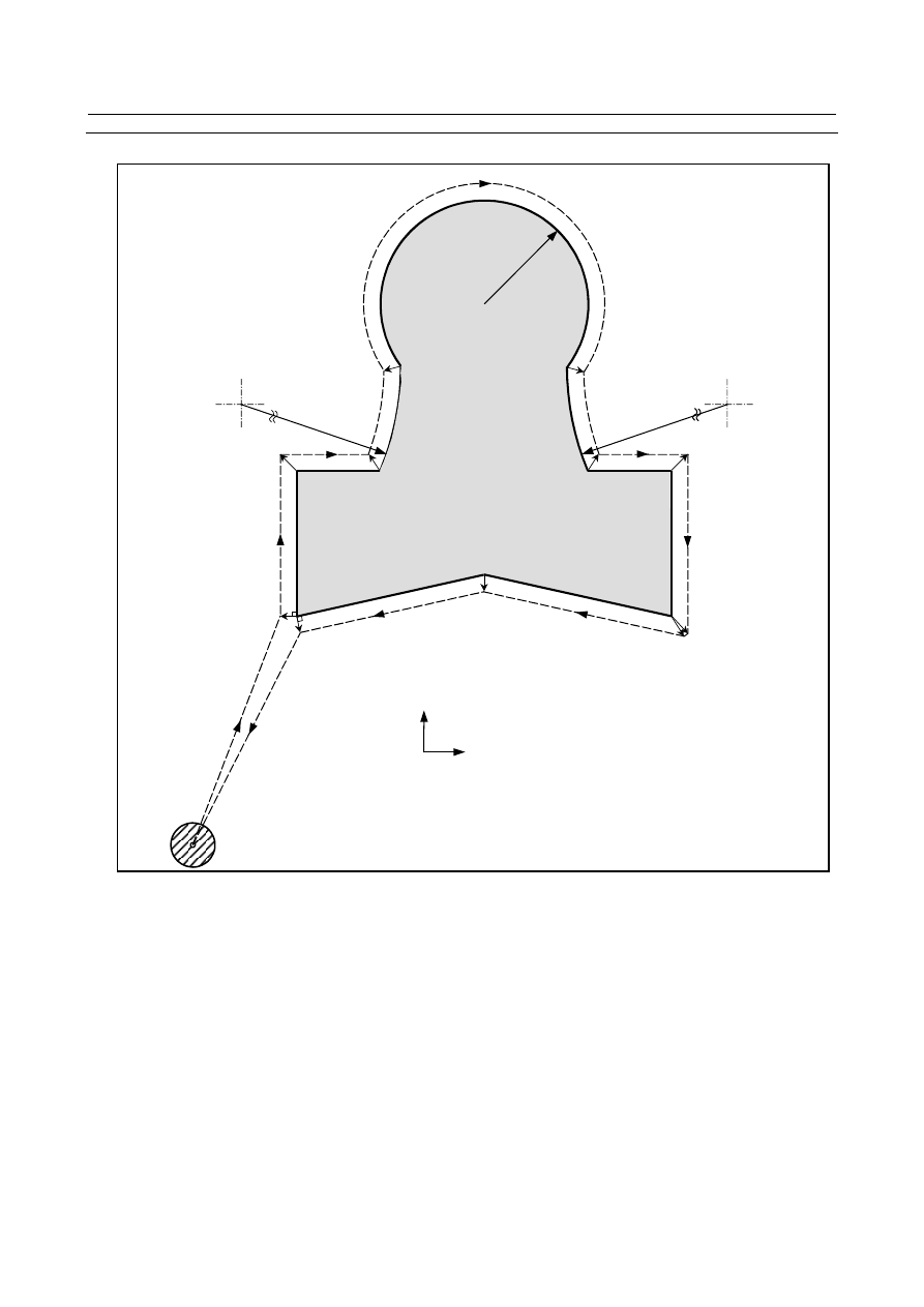
Example 

Y axis

X axis

Unit : mm

Start point

N1

650R

C2 (1550,1150)

650R

C3

(-150,1150)

250R

C1(700,1300)

P4(500,1150)

P5(900,1150)

P6(950,900)

P9(700,650)

P8

(1150,550)

P7

(1150,900)

P1
(250,550)

P3(450,900)

P2

(250,900)

N2

N3

N4

N5

N6

N7

N8

N9

N10

N11


G50 X0 Y0 Z0 ;

............................................Specifies absolute coordinates. 


The tool is positioned at the start point (X0, Y0, Z0). 

N1  G17 G00 G41 T0707 X250.0 Y550.0 ;

....Starts cutter compensation (start-up). 


The tool is shifted to the left of the programmed path by 
the distance specified in T07. 


In other words the tool path is shifted by the radius of the 
tool (offset mode) because T07 is set to 15 beforehand (the 
radius of the tool is 15 mm).   

N2  G01 Y900.0 F150 ;

.....................................Specifies machining from P1 to P2. 

N3 X450.0 ;

........................................................Specifies machining from P2 to P3. 

N4  G03 X500.0 Y1150.0 R650.0 ;

..................Specifies machining from P3 to P4. 

N5  G02 X900.0 R-250.0 ;

................................Specifies machining from P4 to P5. 

N6  G03 X950.0 Y900.0 R650.0 ;

....................Specifies machining from P5 to P6. 

N7  G01 X1150.0 ;

.............................................Specifies machining from P6 to P7. 

N8 Y550.0 ;

........................................................Specifies machining from P7 to P8. 

N9  X700.0 Y650.0 ;

..........................................Specifies machining from P8 to P9. 

5.COMPENSATION FUNCTION

 PROGRAMMING 

 B-64604EN-1/01


- 170 - 

N10 X250.0 Y550.0 ;

..........................................Specifies machining from P9 to P1. 

N11 G00 G40 X0 Y0 ;

.........................................Cancels the offset mode. 


The tool is returned to the start point (X0, Y0, Z0). 

 B-64604EN-1/01

 PROGRAMMING 

5.COMPENSATION FUNCTION


- 171 - 

5.4 

DETAILS OF CUTTER OR TOOL NOSE RADIUS 
COMPENSATION 

5.4.1 

Overview 

The following explanation focuses on tool nose radius compensation, but applies to cutter compensation 
as well. Examples in which XY planes are used, however, apply to cutter compensation only. 
 

  - 

Tool nose radius center offset vector 

The tool nose radius center offset vector is a two dimensional vector equal to the offset value specified in 
a T code, and the vector is calculated in the CNC. Its dimension changes block by block according to tool 
movement. 
This offset vector (simply called vector herein after) is internally created by the control unit as required 
for proper offsetting and to calculate a tool path with exact offset (by tool nose radius) from the 
programmed path. 
This vector is deleted by resetting. 
The vector always accompanies the tool as the tool advances. 
Proper understanding of vector is essential to accurate programming. 
Read the description below on how vectors are created carefully. 
 

  - 

G40, G41, G42 

G40, G41 or G42 is used to delete or generate vectors. 
These codes are used together with G00, G01, G02, or G32 to specify a mode for tool motion 
(Offsetting). 
 

G code 

Workpiece position 

Function 

G40 

Neither 

Tool nose radius compensation cancel 

G41 

Right 

Left offset along tool path 

G42 

Left 

Right offset along tool path 

 
G41 and G42 specify an offset mode, while G40 specifies cancellation of the offset. 
 

  - 

Inner side and outer side 

When an angle of intersection of the tool paths specified with move commands for two blocks on the 
workpiece side is over 180

°

, it is referred to as "inner side." When the angle is between 0

°

 and 180

°

, it is 

referred to as "outer side." 

α

Workpiece

α

Programmed path

Inner side

180

°≤

a

0

°≤α

<180

°

Outer side

Workpiece

Programmed path


  - 

Outer corner connection method 

If the tool moves around an outer corner in tool nose radius compensation mode, it is possible to specify 
whether to connect compensation vectors with linear interpolation or with circular interpolation, using bit 
2 (CCC) of parameter No. 19607. 

5.COMPENSATION FUNCTION

 PROGRAMMING 

 B-64604EN-1/01


- 172 - 

Vectors are connected with linear
interpolation.

Vectors are connected with circular
interpolation.


Fig. 5.4.1 (a) Linear connection type    Fig.5.4.1 (b) Circular connection type 

[Bit 2 (CCC) of parameter No. 19607 = 0]


  [Bit 2 (CCC) of parameter No. 19607 = 1] 


 -  Cancel mode 

The tool nose radius compensation enters the cancel mode under the following conditions. (The system 
may not enter the cancel mode depending on the machine tool.) 
(1)  Immediately after the power is turned on 

(2) After 

the 

  key on the MDI unit is pushed 

(3)  After a program is forced to end by executing M02 or M30 
(4)  After the tool nose radius compensation cancel command (G40) is exercised 
In the cancel mode, the magnitude of a compensation vector is 0 at all times and the path of the virtual 
tool nose matches the programmed path. A program must end in cancel mode. If it ends in the tool nose 
radius compensation mode, the tool cannot be positioned at the end point, and the tool stops at a location 
the compensation vector length away from the end point. 
 

NOTE 


The operation performed when a reset operation is performed during tool nose 
radius compensation varies according to the setting of bit 6 (CLR) of parameter 
No. 3402. 

 When 

CLR=0 

The reset state is set. The modal information of G41/G42 in group 07 is 
preserved. To perform tool nose radius compensation, however, an offset 
number (T code) needs to be specified again. 

 When 

CLR=1 

The cleared state is set. The modal information of G40 in group 07 is 
preserved. To perform tool nose radius compensation, G41/G42 and an 
offset number (T code) need to be specified. 


 -  Start-up 

When a block which satisfies all the following conditions is executed in cancel mode, the CNC enters the 
offset mode. Control during this operation is called start-up. 
 
(1)  G41 or G42 is contained in the block, or has been specified to place the CNC in the offset mode. 
(2)  0 < compensation number of tool nose radius compensation 

 maximum compensation number 

(3)  Positioning (G00) or linear interpolation (G01) mode 
(4)  A compensation plane axis command with a travel distance of 0 (except start-up type C) is specified. 
If start-up is specified in circular interpolation (G02, G03) mode, alarm PS0034, “NO CIRC ALLOWED 
IN STUP/EXT BLK” will occur. 
Workpiece coordinate system switching (G54 to G59) cannot be specified in the start-up block. 

 B-64604EN-1/01

 PROGRAMMING 

5.COMPENSATION FUNCTION


- 173 - 

As a start-up operation, one of the three types A, B, and C can be selected by setting bits 0 (SUP) and 1 
(SUV) of parameter No. 5003 appropriately. The operation to be performed if the tool moves around an 
inner side is of single type only. 
 

Table 5.4.1 (a) Start-up/cancel operation 

SUV SUP 

Type 

Operation 

Type A 

A compensation vector is output, which is vertical to the block 
subsequent to the start-up block and the block preceding the cancel 
block. 

G41

N1

N2

Tool nose radius center path

Programmed path


Type B 

A compensation vector is output, which is vertical to the start-up 
block and the cancel block. An intersection vector is also output. 

G41

N1

N2

Intersection

Tool nose radius center path

Programmed path


1 0 

Type C 

When the start-up block and the cancel block are blocks without tool 
movement, the tool moves by the cutter or tool nose radius 
compensation value in the direction vertical to the block subsequent 
to the start-up block and the block preceding the cancel block. 

G41

N1

N2

Intersection

Tool nose radius center path

Programmed path

N3

Programmed
path


For a block with tool movement, the tool follows the SUP setting: If it 
is 0, type A is assumed and if 1, type B is assumed. 


  - 

Reading input commands in tool nose radius compensation mode 

In tool nose radius compensation mode, input commands are read from usually three blocks and up to 
eight blocks depending on the setting of parameter No. 19625 to perform intersection calculation or an 
interference check, described later, regardless of whether the blocks are with or without tool movement, 
until a cancel command is received. 
To perform intersection calculation, it is necessary to read at least two blocks with tool movement. To 
perform an interference check, it is necessary to read at least three blocks with tool movement. 
 
As the setting of parameter No. 19625, that is, the number of blocks to read, increases, it is possible to 
predict overcutting (interference) for up to more subsequent commands. Increases in blocks to read and 
analyze, however, cause reading and analysis to take more time. 
 

5.COMPENSATION FUNCTION

 PROGRAMMING 

 B-64604EN-1/01


- 174 - 

  - 

Bit 0 (SBK) of parameter No. 5000 

When bit 0 (SBK) of parameter No. 5000 is set to 1, a single block stop can be performed in a block 
created internally for tool nose radius compensation. 
Use this parameter to check a program including tool nose radius compensation. 

Single block stop point


S

Stop point in a block created internally

Programmed path 

Tool nose radius center path

N1 

N2

N1 

N1

N2


NOTE 


When an auxiliary function (M code), spindle speed function (S code), tool 
function (T code), or second auxiliary function (B code) is specified in the N1 
block in the figure above, FIN is not accepted if the tool stops at the stop point in 
a block created internally (excluding the single block stop point). 


  - 

Meaning of symbols 

The following symbols are used in subsequent figures: 


S indicates a position at which a single block is executed once. 


SS indicates a position at which a single block is executed twice. 


SSS indicates a position at which a single block is executed three times. 


L indicates that the tool moves along a straight line. 


C indicates that the tool moves along an arc. 


r indicates the cutter or tool nose radius compensation value. 


An intersection is a position at which the programmed paths of two blocks intersect with each other 
after they are shifted by r.   


  indicates the center of the tool nose radius. 


 B-64604EN-1/01

 PROGRAMMING 

5.COMPENSATION FUNCTION


- 175 - 

5.4.2 

Tool Movement in Start-up 

When the offset cancel mode is changed to offset mode, the tool moves as illustrated below (start-up): 
 

Explanation 

  - 

Tool movement around an inner side of a corner (180

°≤


α

α

L

S

G42

r

L

α

S

r

L

C

G42

Tool nose radius
center path

Start point

Programmed path

Work-
piece

Linear

Circular

Start point

Workpiece

Tool nose radius center path

Linear

Linear

Programmed path


5.COMPENSATION FUNCTION

 PROGRAMMING 

 B-64604EN-1/01


- 176 - 

  - 

Cases in which the start-up block is a block with tool movement and the tool 
moves around the outside at an obtuse angle (90

°≤


α

<180

°

Tool path in start-up has two types A and B, and they are selected by bit 0 (SUP) of parameter No. 5003. 

Linear

Linear

α

Programmed path

Tool nose radius
center path

L

S

G42

r

L

Linear

Circular

r

Type

A

Type

B

α

L

S

G42

L

Workpiece

Start point

r

L

Linear

Linear

(Linear connection type)

Linear

Circular

(Linear connection type)

Workpiece

Start point

Start point

Work-
piece

Programmed path

Tool nose radius
center path

Tool nose radius center path

Intersection

Intersection

Work
piece

Programmed path

Start point

C

G42

L

r

S

α

Tool nose radius center path

L

L

α

S

C

G42

r

L

r

Programmed path

Work-
piece


 B-64604EN-1/01

 PROGRAMMING 

5.COMPENSATION FUNCTION


- 177 - 

Type

B

Linear

Linear

(Circular
connection type)

Linear

Circular

(Circular
connection type)

Programmed path

Tool nose radius center path

Start point

L

α

S

C

G42

Workpiece

r

r

r

α

Programmed path

Tool nose radius
center path

L

S

G42

L

Workpiece

Start point

r

C

C


5.COMPENSATION FUNCTION

 PROGRAMMING 

 B-64604EN-1/01


- 178 - 

  - 

Cases in which the start-up block is a block with tool movement and the tool 
moves around the outside at an acute angle (

α

<90

°

Tool path in start-up has two types A and B, and they are selected by bit 0 (SUP) of parameter No. 5003. 

α

L

S

G42

r

L

S C

Type

A

Type

B

r

G42

L

G42

L

L

L

L

S

r

r

G42

L

L

L

S

r

r

C

L

L

Linear

Linear

Linear

Circular

Linear

Linear

(Linear connection type)

Linear

Circular

(Linear connection type)

Workpiece

Work-
piece

Workpiece

Work-
piece

Start point

Start point

Start point

Start point

Programmed path

Programmed path

Programmed path

Programmed path

Tool nose radius center path

Tool nose radius center path

Tool nose radius center path

α

α

α

Tool nose radius center path


 B-64604EN-1/01

 PROGRAMMING 

5.COMPENSATION FUNCTION


- 179 - 

Type

B

Programmed path

α

G42

Start point

L

L

C

S

r

r

Tool nose radius center path

α

G42

Start point

L

C

S

r

r

Programmed path

Tool nose radius center path

C

Workpiece

Work-
piece

Linear

Linear

(Circular
connection type)

Linear

Circular

(Circular
connection type)


  - 

Tool movement around the outside linear 

 linear at an acute angle less than 

1 degree (

α

<1

°

r

G41

(G41)

L

L

S

Start point

Tool nose radius center path

Programmed path

Less than 1 deg


  - 

A block without tool movement specified at start-up 

For type A and B 
 

If the command is specified at start-up, the offset vector is not created. The tool does not operate in a 
start-up block. 


Programmed path 

Tool nose radius 
center path 

S

N9 

N6 

N7 

N8 

SS 

G40 … ; 
 
N6 U100.0 W100.0 ; 
N7 G41 U0 ; 
N8 U-100.0 ; 
N9 U-100.0 W100.0 ; 


5.COMPENSATION FUNCTION

 PROGRAMMING 

 B-64604EN-1/01


- 180 - 

For type C 
 

The tool shifts by the compensation value in the direction vertical to the block with tool movement 
subsequent to the start-up block. 

Programmed path

Tool nose radius center path

S

Intersection

α

L

L

Without tool
movement

S


 B-64604EN-1/01

 PROGRAMMING 

5.COMPENSATION FUNCTION


- 181 - 

5.4.3 

Tool Movement in Offset Mode 

In offset mode, compensation is performed even for positioning commands, not to speak of linear and 
circular interpolations. To perform intersection calculation, it is necessary to read at least two blocks with 
tool movement. If, therefore, two or more blocks with tool movement cannot be read in offset mode 
because blocks without tool movement, such as auxiliary function independent commands and dwell, are 
specified in succession, excessive or insufficient cutting may occur because intersection calculation fails. 
Assuming the number of blocks to read in offset mode, which is determined by parameter No. 19625, to 
be N and the number of commands in those N blocks without tool movement that have been read to be M, 
the condition under which intersection calculation is possible is (N - 2) 

 M. For example, if the 

maximum number of blocks to read in offset mode is 5, intersection calculation is possible even if up to 
three blocks without tool movement are specified. 
 

NOTE 


The condition necessary for an interference check, described later, differs from 
this condition. For details, see the explanation of the interference check. 

 
If a G or M code in which buffering is suppressed is specified, no subsequent commands can be read 
before that block is executed, regardless of the setting of parameter No. 19625. Excessive or insufficient 
cutting may, therefore, occur because of an intersection calculation failure. 
 

5.COMPENSATION FUNCTION

 PROGRAMMING 

 B-64604EN-1/01


- 182 - 

  - 

Tool movement around the inside of a corner (180

°≤


α

α

C

L

S

S

α

L

L

Linear

Linear

Programmed path

Intersection

Tool nose radius
center path

Workpiece

S

Linear

Circular

Intersection

Programmed path

Tool nose radius
center path

Work-
piece

Circular

Linear

α

Intersection

L

C

Programmed path

Tool nose radius
center path

S

C

C

Circular

Circular

Programmed path

Intersection

α

Workpiece

Tool nose radius
center path

Work-
piece


 B-64604EN-1/01

 PROGRAMMING 

5.COMPENSATION FUNCTION


- 183 - 

  - 

Tool movement around the inside (

α

<1

°

) with an abnormally long vector, 

linear 

 linear 


Intersection 

Intersection 

Programmed path

Tool nose radius center path 

S


Also in case of arc to straight line, straight line to arc and arc to arc, the reader should infer in the same 
procedure. 
 

5.COMPENSATION FUNCTION

 PROGRAMMING 

 B-64604EN-1/01


- 184 - 

Tool movement around the outside corner at an obtuse angle (90

°≤α

<180

°

Linear

Linear

(Linear
connection type)

Tool nose radius
center path

Tool nose radius
center path

Programmed path

α

Programmed path

L

Workpiece

S

Intersection

L

r

α

C

Work-
piece

L

S

L

α

C

L

S

Workpiece

r

L

α

Tool nose
radius center
path

L

L

S

Intersection

r

r


C

C

Linear

Circular

(Linear
connection type)

Circular

Linear

(Linear
connection type)

Circular

Circular

(Linear
connection type)

Intersection

Tool nose radius
center path

Programmed path

Intersection

Programmed path

Work-
piece


Content      ..     10      11      12      13     ..