FANUC Series 0i-MODEL F. For Lathe System OPERATOR'S MANUAL (B-64604EN-1/01) - page 5
 

  Index      Manuals     FANUC Series 0i-MODEL F. For Lathe System OPERATOR'S MANUAL (B-64604EN-1/01)


Search            copyright infringement  


Content      ..     3      4      5      6     ..


FANUC Series 0i-MODEL F. For Lathe System OPERATOR'S MANUAL (B-64604EN-1/01) - page 5


 B-64604EN-1/01

 PROGRAMMING 


- 57 - 

4.FUNCTIONS TO SIMPLIFY 

PROGRAMMING

(1)  In the block with sequence number ns, the two axes forming the plane (X-axis (U-axis) and Z-axis 

(W-axis) for the ZX plane) must be specified. When you want to use type II without moving the tool 
along the Z-axis on the ZX plane in the first block, specify W0. 


Example 

 ZX 

plane 


G71 U10.0 R5.0; 


G71 P100 Q200.......; 


N100 X(U)_ Z(W)_ ;

  (Specifies the two axes forming the plane.) 


                    :    ; 


                    :    ; 

 N200…………; 

 
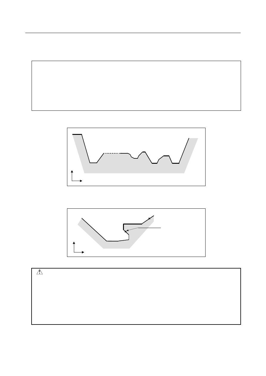
(2)  The figure need not show monotone increase or decrease in the direction of the second axis on the 

plane (X-axis for the ZX plane) and it may have concaves (pockets). 

1

2

3

10

. . .

+X

+Z


Fig. 4.2.1 (f) Figure having pockets (type II) 


The figure must show monotone change in the direction of the first axis on the plane (Z-axis for the 
ZX plane), however. The Fig. 4.2.1 (g) cannot be machined. 

Monotone change is not
observed along the Z-
axis.

+X

+Z


Fig. 4.2.1 (g) Figure which cannot be machined (type II) 


 CAUTION 


For a figure along which the tool moves backward along the first axis on the 
plane during cutting operation (including a vertex in an arc command), the 
cutting tool may contact the workpiece. For this reason, for a figure which does 
not show monotone change, alarm PS0064 “THE FINISHING SHAPE IS NOT A 
MONOTONOUS CHANGE(FIRST AXES)” is issued. If the movement does not 
show monotone change, but is very small, and it can be determined that the 
movement is not dangerous, however, the permissible amount can be specified 
in parameter No. 5145 to specify that the alarm is not issued in this case. 


The first cut portion need not be vertical. Any figure is permitted if monotone change is shown in 
the direction of the first axis on the plane (Z-axis for the ZX plane). 

 PROGRAMMING 

 B-64604EN-1/01


- 58 - 

4. FUNCTIONS TO SIMPLIFY 

PROGRAMMING 

+ X

+ Z


Fig. 4.2.1 (h) Figure which can be machined (type II) 

 
(3)  After turning, the tool cuts the workpiece along its figure and escapes in cutting feed. 
 

Escaping amount e (specified in the command or
parameter No. 5133)

Depth of cut 

Δ

d (specified in the

command or parameter No. 5132)

Escaping after cutting


Fig. 4.2.1 (i) Cutting along the workpiece figure (type II) 


The escaping amount after cutting (e) can be specified at address R or set in parameter No. 5133. 


When moving from the bottom, however, the tool escapes to the direction of 45 degrees. 

e (specified in the command or

parameter No. 5133)

45

°

Bottom


Fig. 4.2.1 (j) Escaping from the bottom to the direction of 45 degrees 

 
(4)  When a position parallel to the first axis on the plane (Z-axis for the ZX plane) is specified in a 

block in the program for the target figure, it is assumed to be at the bottom of a pocket. 

 
(5)  After all rough cutting terminates along the first axis on the plane (Z-axis for the ZX plane), the tool 

temporarily returns to the cycle start point. At this time, when there is a position whose height equals 
to that at the start point, the tool passes through the point in the position obtained by adding depth of 
cut 

Δ

d to the position of the figure and returns to the start point. 


Then, rough cutting is performed as finishing along the target figure. At this time, the tool passes 
through the point in the obtained position (to which depth of cut 

Δ

d is added) when returning to the 

start point. 


Bit 2 (RF2) of parameter No. 5105 can be set to 1 so that rough cutting as finishing is not performed. 

 B-64604EN-1/01

 PROGRAMMING 


- 59 - 

4.FUNCTIONS TO SIMPLIFY 

PROGRAMMING

Depth of cut 

Δ

d

{

Start point

{

Escaping operation after
rough cutting

Escaping operation after rough cutting
as finishing


Fig. 4.2.1 (k) Escaping operation when the tool returns to the start point (type II) 

 
(6)  Order and path for rough cutting of pockets 
 

Rough cutting is performed in the following order. 
(a)  When the figure shows monotone decrease along the first axis on the plane (Z-axis for the ZX 

plane) 

<1>

<2>

<3>

Rough cutting is performed in the order <1>, <2>, and <3>
from the rightmost pocket.

+X

+Z


Fig. 4.2.1 (l) Rough cutting order in the case of monotone decrease (type II) 


(b)  When the figure shows monotone increase along the first axis on the plane (Z-axis for the ZX 

plane) 

<3>

<2>

<1>

Rough cutting is performed in the order <1>, <2>, and <3> from
the leftmost pocket.

+X

+Z


Fig. 4.2.1 (m) Rough cutting order in the case of monotone increase (type II) 


The path in rough cutting is as shown Fig. 4.2.1 (n). 

 PROGRAMMING 

 B-64604EN-1/01


- 60 - 

4. FUNCTIONS TO SIMPLIFY 

PROGRAMMING 


18

23

28


30


27


26

24


25

22

9

10

2

14

20

7

13

19

5

1


6

11

12

16

17

8

4

21

15

29


3


31


32


33


34


35


Fig. 4.2.1 (n) Cutting path for multiple pockets (type II) 

 
The following figure shows how the tool moves after rough cutting for a pocket in detail. 

19

20

22

21

g

Rapid traverse

Escaping from
the bottom

Cutting feed

D


Fig. 4.2.1 (o) Details of motion after cutting for a pocket (type II) 

 
Cuts the workpiece at the cutting feedrate and escapes to the direction of 45 degrees. (Operation 19) 
Then, moves to the height of point D in rapid traverse. (Operation 20) 
Then, moves to the position the amount of g before point D. (Operation 21) 
Finally, moves to point D in cutting feed. 
The clearance g to the cutting feed start position is set in parameter No. 5134. 
For the last pocket, after cutting the bottom, the tool escapes to the direction of 45 degrees and returns to 
the start point in rapid traverse. (Operations 34 and 35) 
 

 CAUTION 

1  This CNC differs from the FANUC Series 0

i

-C in cutting of a pocket. 


The tool first cuts the nearest pocket to the start point. After cutting of the pocket 
terminates, the tool moves to the nearest but one pocket and starts cutting. 

2  When the figure has a pocket, generally specify a value of 0 for 

Δ

w (finishing 

allowance). Otherwise, the tool may dig into the wall on one side. 

 
This CNC differs from the FANUC Series 0

i

-C in the path of cutting after turning depending on the 

figure of the workpiece. When the tool becomes moving only along the first axis on the plane (Z-axis for 
the ZX plane) according to the figure of the workpiece during cutting, it starts retraction along the second 
axis on the plane (X-axis for the ZX plane). 
When bit 0 (R16) of parameter No. 5108 is set to 1, the cutting can be continued along the first axis on 
the plane. 
The cutting path that the target figure program of Fig. 4.2.1 (n) is executed by the setting of bit 0 (R16) of 
parameter No. 5108, is shown in Fig. 4.2.1 (p). 
 

 B-64604EN-1/01

 PROGRAMMING 


- 61 - 

4.FUNCTIONS TO SIMPLIFY 

PROGRAMMING


Fig. 4.2.1 (p)    Cutting path (No.5108#0 is set to 1) 


  - 

Tool nose radius compensation 

When using tool nose radius compensation, specify a tool nose radius compensation command (G41, 
G42) before a multiple repetitive canned cycle command (G70, G71, G72, G73) and specify the cancel 
command (G40) outside the programs (from the block specified with P to the block specified with Q) 
specifying a target finishing figure.   
If tool nose radius compensation is specified in the program specifying a target finishing figure, alarm 
PS0325, “UNAVAILABLE COMMAND IS IN SHAPE PROGRAM”, is issued. 
 
Program example 
G42;..............................Specify this command before a multiple repetitive canned cycle command. 
G71U1.0R0.5; 
G71P10Q20; 
N10G00X0; 
 : 
N20X50.0; 
G40;..............................Specify this command after the program specifying a target finishing figure. 
 
When this cycle is specified in the tool nose radius compensation mode, offset is temporarily canceled 
during movement to the start point. Start-up is performed in the first block. Offset is temporarily canceled 
again at the return to the cycle start point after termination of cycle operation. Start-up is performed again 
according to the next move command. This operation is shown in the Fig. 4.2.1 (q). 

Cycle start point

Start-up

z

Offset cancel

Start-up

Offset cancel


Fig. 4.2.1 (q)


 PROGRAMMING 

 B-64604EN-1/01


- 62 - 

4. FUNCTIONS TO SIMPLIFY 

PROGRAMMING 

This cycle operation is performed according to the figure determined by the tool nose radius 
compensation path when the offset vector is 0 at start point A and start-up is performed in a block 
between path A-A'. 

Target figure program for
which tool nose radius
compensation is not applied

+X

+Z

B

A

A’

Tool nose center path when tool nose radius
compensation is applied with G42

Position between A-
A' in which start-up is
performed


Fig. 4.2.1 (r) Path when tool nose radius compensation is applied


Target figure program for
which tool nose radius
compensation is not applied

+X

+Z

Tool nose center path when tool
nose radius compensation is
applied with G42

B

A

A’

Position between
A-A' in which start-
up is performed


Fig. 4.2.1 (s)     


NOTE 


To perform pocketing in the tool nose radius compensation mode, specify the 
linear block A-A' outside the workpiece and specify the figure of an actual 
pocket. This prevents a pocket from being dug. 

 
When the bit 2 (NT1) of parameter No. 5106 is set to 1, the tool nose radius compensation G40/G41/G42 
commanded in the target figure program of the multiple repetitive cycle G71/G72/G73 is ignored and no 
alarm is occurred. 
 
When the bit 3 (NT2) of parameter No. 5106 is set to 1, the tool nose radius compensation commanded in 
the target figure program of the multiple repetitive cycle G70 is valid. However there is following 
limitations. 
(1)  The tool nose radius compensation cancel G40 is selected as the modal when the finishing cycle G70 

is commanded. 


If the tool nose radius compensation is commanded in the target figure program when G41/G42 is 
selected as the modal at the finishing cycle G70 command, the alarm PS0325 “UNAVAILABLE 
COMMAND IS IN SHAPE PROGRAM” is occurred. 

 B-64604EN-1/01

 PROGRAMMING 


- 63 - 

4.FUNCTIONS TO SIMPLIFY 

PROGRAMMING

(2)  Do not command G41/G42 excluding the end block in the target figure program. 
 

If G41 or G42 is specified at the last block of the target figure program, the PS0325 alarm 
(UNAVAILABLE COMMAND IS IN SHAPE PROGRAM) is issued. 

(3)  Command G40 at the last block of the target figure program (commanded by Q address) 
 

If G40 is not commanded at the last block of the target figure program when G41 or G42 is 
commanded at the first block, the PS0538 alarm “OFFSET IS NOT CANCELED” is occurred. 

 
Program example of the tool nose radius compensation in the target figure of G70) 
 G40 


G70 P10 Q20 ... ; 


N10 G41 ... ; 


N20 G40 ... ; 


  - 

Reducing the cycle time 

In the multiple repetitive cycle G71/G72 of type

, if bit 1 (DTP) of parameter No. 5108 is set to 1, the 

tool return to the cycle start point directly from the end point of the finishing program after rough cutting 
of the finishing shape program is finished. 
 

Cycle start point


Path of DTP = 1

Path of DTP = 0


End point of finishing 
shape


Cycle start point 


Distance of the finishing 
allowance


Fig. 4.2.1 (t)    Return to cycle start point 

 
In the multiple repetitive cycle G71/G72 of type II, when bit 3 (NSP) of parameter No. 5108 is set to 1, 
the cutting is executed not to repeat the same cutting path. (When bit 3 (NSP) of parameter No. 5108 is 
set to 1, the operation of bit 0 (R16) of parameter No. 5108 = 1 is always selected.)


Case of target figure without pocket. 


In the conventional method, the path AB is cut twice as Fig. 4.2.1 (w). 


When bit 3 (NSP) of parameter No. 5108 is set to 1, the overlap is avoided as Fig. 4.2.1(x). 


Fig. 4.2.1 (u)    Target figure without pocket (No.5108#3=0) 


 PROGRAMMING 

 B-64604EN-1/01


- 64 - 

4. FUNCTIONS TO SIMPLIFY 

PROGRAMMING 


Fig. 4.2.1 (v)    Target figure without pocket (No.5108#3=1) 


Case of target figure with pocket. 


In the conventional method, the path AB and CD are cut twice as Fig. 4.2.1 (y). 


The cutting path when bit 3 (NSP) of parameter No. 5108 is set to 1 is shown in Fig. 4.2.1(z). The 
path AB is overlapped as same as Fig. 4.2.1 (y), however the path AB is executed by rapid traverse 
at second times. The overlap path CD is avoided. 

(1)

(2)

(3)

(4)


Fig. 4.2.1 (w)    Target figure with pocket (No.5108#3=0) 


(1)

(2)

(3)

(4)


Fig. 4.2.1 (x)    Target figure with pocket (No.5108#3=1) 


Case of consecutive pockets 


In the conventional method, the tool moves to point I after finish the cutting of a pocket and 
positioning to the start point of a next pocket as Fig. 4.2.1 (aa). In this way, the path is overlapped at 
BI, DI, FI and HI. 


The cutting path when bit 3 (NSP) of parameter No. 5108 is set to 1 is shown in Fig. 4.2.1(bb). The 
movement to point I is executed just first time and then the pocket cutting is executed one after 
another. 

A

D

G


Fig. 4.2.1 (y)    Consecutive pockets (No.5108#3=0) 


 B-64604EN-1/01

 PROGRAMMING 


- 65 - 

4.FUNCTIONS TO SIMPLIFY 

PROGRAMMING

A

D

G


Fig. 4.2.1 (z)    Consecutive pockets (No.5108#3=1) 


 PROGRAMMING 

 B-64604EN-1/01


- 66 - 

4. FUNCTIONS TO SIMPLIFY 

PROGRAMMING 

4.2.2 

Stock Removal in Facing (G72) 

This cycle is the same as G71 except that cutting is performed by an operation parallel to the second axis 
on the plane (X-axis for the ZX plane). 
 

Format 

ZpXp plane 

G72 W(

Δ

d) R(e) ; 

G72 P(ns) Q(nf) U(

Δ

u) W(

Δ

w) F(f ) S(s ) T(t ) ; 

N (ns) ; 

  ... 

N (nf) ; 

The move commands for the target figure from A 
to A’ to B are specified in the blocks with 
sequence numbers ns to nf. 


YpZp plane 

G72 V(

Δ

d) R(e) ; 

G72 P(ns) Q(nf) V(

Δ

w) W(

Δ

u) F(f ) S(s ) T(t ) ; 

N (ns) ; 

  ... 

N (nf) ; 

XpYp plane 

G72 U(

Δ

d) R(e) ; 

G72 P(ns) Q(nf) U(

Δ

w) V (

Δ

u) F(f ) S(s ) T(t ) ; 

N (ns) ; 

  ... 

N (nf) ; 

Δ

d  :  Depth of cut 


  The cutting direction depends on the direction AA'. This designation is modal and is not 

changed until the other value is designated. Also this value can be specified by the 
parameter No. 5132, and the parameter is changed by the program command. 

e : 

Escaping 

amount 


  This designation is modal and is not changed until the other value is designated. Also 

this value can be specified by the parameter No. 5133, and the parameter is changed 
by the program command. 

ns  :  Sequence number of the first block for the program of finishing shape. 
nf  :  Sequence number of the last block for the program of finishing shape. 

Δ

u  :  Distance of the finishing allowance in the direction of the second axis on the plane 

(X-axis for the ZX plane) 

Δ

w  :  Distance of the finishing allowance in the direction of the first axis on the plane (Z-axis 

for the ZX plane) 

f,s,t :  Any F , S, or T function contained in blocks ns to nf in the cycle is ignored, and the F, S, 

or T function in this G72 block is effective.


 Unit  Diameter/radius 

programming 

Sign 

Decimal point 

input 

Δ

Depends on the increment 
system for the reference axis. 

Radius programming 

Not 

required 

Allowed 

Depends on the increment 
system for the reference axis. 

Radius programming 

Not 

required 

Allowed 

 B-64604EN-1/01

 PROGRAMMING 


- 67 - 

4.FUNCTIONS TO SIMPLIFY 

PROGRAMMING

 Unit  Diameter/radius 

programming 

Sign 

Decimal point 

input 

Δ

Depends on the increment 
system for the reference axis. 

Depends on diameter/radius programming 
for the second axis on the plane. 

Required Allowed 

Δ

Depends on the increment 
system for the reference axis. 

Depends on diameter/radius programming 
for the first axis on the plane. 

Required Allowed 


A'

Δ

u/2


Δ

d

B

Tool path

(F)

(R)

e

 45

°

(R)

(F)

A

C


Δ

w

Target figure

(F):  Cutting feed
(R):  Rapid traverse

+X

+Z


Fig. 4.2.2 (a) Cutting path in stock removal in facing (type I) 


Explanation 

 -  Operations 

When a target figure passing through A, A', and B in this order is given by a program, the specified area 
is removed by 

Δ

d (depth of cut), with the finishing allowance specified by 

Δ

u/2 and 

Δ

w left. 


NOTE 

1 While 

both 

Δ

d and 

Δ

u are specified by the same address, the meanings of them 

are determined by the presence of addresses P and Q. 

2  The cycle machining is performed by G72 command with P and Q specification. 
3  F, S, and T functions which are specified in the move command between points 

A and B are ineffective and those specified in G72 block or the previous block 
are effective. M and second auxiliary functions are treated in the same way as F, 
S, and T functions. 

4  When the constant surface speed control function is enabled (bit 0 (SSC) of 

parameter No. 8133 is set to 1), G96 or G97 command specified in the move 
command between points A and B are ineffective, and that specified in G72 
block or the previous block is effective. 


 -  Target figure  
 Patterns 

The following four cutting patterns are considered. All of these cutting cycles cut the workpiece with 
moving the tool in parallel to the second axis on the plane (X-axis for the ZX plane). At this time, the 
signs of the finishing allowances of 

Δ

u and 

Δ

w are as follows: 

 PROGRAMMING 

 B-64604EN-1/01


- 68 - 

4. FUNCTIONS TO SIMPLIFY 

PROGRAMMING 

Both linear and circular

interpolation are possible

+X

+Z

B

A

U(-)...W(+)...

A'

B

A

U(-)...W(-)...

A'

B

A

U(+)...W(+)...

A'

B

A

U(+)...W(-)...

A'


Fig. 4.2.2 (b) Signs of the values specified at U and W in stock removal in facing 


 Limitation 

(1)  For W(+), a figure for which a position higher than the cycle start point is specified cannot be 

machined. 


For W(-), a figure for which a position lower than the cycle start point is specified cannot be 
machined. 

(2)  For type I, the figure must show monotone increase or decrease along the first and second axes on 

the plane. 

(3)  For type II, the figure must show monotone increase or decrease along the second axis on the plane. 
 

 -  Start block 

In the start block in the program for a target figure (block with sequence number ns in which the path 
between A and A' is specified), G00 or G01 must be specified. If it is not specified, alarm PS0065, 
“G00/G01 IS NOT IN THE FIRST BLOCK OF SHAPE PROGRAM” is issued. 
When G00 is specified, positioning is performed along A-A’. When G01 is specified, linear interpolation 
is performed with cutting feed along A-A’. 
In this start block, also select type I or II. 
If Z-axis does not move at start block, alarm PS0325 “UNAVAILABLE COMMAND IS IN SHAPE 
PROGRAM” is issued. 
 

 -  Check functions 

During cycle operation, whether the target figure shows monotone increase or decrease is always 
checked. 
 

NOTE 


When tool nose radius compensation is applied, the target figure to which 
compensation is applied is checked. 

 
The following checks can also be made. 
 

Check Related 

parameter 

Checks that a block with the sequence number specified at address 
Q is contained in the program before cycle operation. 

Enabled when bit 2 (QSR) of parameter 
No. 5102 is set to 1. 

Checks the target figure before cycle operation. 
(Also checks that a block with the sequence number specified at 
address Q is contained.) 

Enabled when bit 2 (FCK) of parameter 
No. 5104 is set to 1. 


 B-64604EN-1/01

 PROGRAMMING 


- 69 - 

4.FUNCTIONS TO SIMPLIFY 

PROGRAMMING

  - 

Types I and II 


Selection of type I or II 

For G72, there are types I and II. 
When the target figure has pockets, be sure to use type II. 
Escaping operation after rough cutting in the direction of the second axis on the plane (X-axis for the ZX 
plane) differs between types I and II. With type I, the tool escapes to the direction of 45 degrees. With 
type II, the tool cuts the workpiece along the target figure. When the target figure has no pockets, 
determine the desired escaping operation and select type I or II. 


Selecting type I or II 

In the start block for the target figure (sequence number ns), select type I or II. 
(1)  When type I is selected 
 

Specify the first axis on the plane (Z-axis for the ZX plane). Do not specify the second axis on the 
plane (X-axis for the ZX plane). 

(2)  When type II is selected 
 

Specify the second axis on the plane (X-axis for the ZX plane) and first axis on the plane (Z-axis for 
the ZX plane). 


When you want to use type II without moving the tool along the second axis on the plane (X-axis for 
the ZX plane), specify the incremental programming with travel distance 0 (U0 for the ZX plane). 
 

 -  Type I 

G72 differs from G71 in the following points: 
(1)  G72 cuts the workpiece with moving the tool in parallel with the second axis on the plane (X-axis on 

the ZX plane). 

(2)  In the start block in the program for a target figure (block with sequence number ns), only the first 

axis on the plane (Z-axis (W-axis) for the ZX plane) must be specified. 
 

 -  Type II 

G72 differs from G71 in the following points: 
(1)  G72 cuts the workpiece with moving the tool in parallel with the second axis on the plane (X-axis on 

the ZX plane). 

(2)  The figure need not show monotone increase or decrease in the direction of the first axis on the 

plane (Z-axis for the ZX plane) and it may have concaves (pockets). The figure must show 
monotone change in the direction of the second axis on the plane (X-axis for the ZX plane), 
however. 

(3)  When a position parallel to the second axis on the plane (X-axis for the ZX plane) is specified in a 

block in the program for the target figure, it is assumed to be at the bottom of a pocket. 

(4)  After all rough cutting terminates along the second axis on the plane (X-axis for the ZX plane), the 

tool temporarily returns to the start point. Then, rough cutting as finishing is performed. 
 

  - 

Tool nose radius compensation 

See the pages on which G71 is explained. 
 

  - 

Reducing the cycle time 

See the pages on which G71 is explained. 
 

 PROGRAMMING 

 B-64604EN-1/01


- 70 - 

4. FUNCTIONS TO SIMPLIFY 

PROGRAMMING 

4.2.3 

Pattern Repeating (G73) 

This function permits cutting a fixed pattern repeatedly, with a pattern being displaced bit by bit. By this 
cutting cycle, it is possible to efficiently cut work whose rough shape has already been made by a rough 
machining, forging or casting method, etc. 
 

Format 

ZpXp plane 

G73 W(

Δ

k) U(

Δ

i) R(d) ; 

G73 P(ns) Q(nf) U(

Δ

u) W(

Δ

w) F(f ) S(s ) T(t ) ; 


N (ns) ; 

 ... 

N (nf) ; 

The move commands for the target figure from A 
to A’ to B are specified in the blocks with 
sequence numbers ns to nf. 


YpZp plane 

G73 V(

Δ

k) W(

Δ

i) R(d) ; 

G73 P(ns) Q(nf) V(

Δ

w) W(

Δ

u) F(f ) S(s ) T(t ) ; 

N (ns) ; 
  ... 
N (nf) ; 

XpYp plane 

G73 U(

Δ

k) V(

Δ

i) R(d) ; 

G73 P(ns) Q(nf) U(

Δ

w) V(

Δ

u) F(f ) S(s ) T(t ) ; 

N (ns) ; 
  ... 
N (nf) ; 

Δ

:  Distance of escape in the direction of the second axis on the plane (X-axis for the ZX 

plane) 


  This designation is modal and is not changed until the other value is designated. Also 

this value can be specified by the parameter No. 5135, and the parameter is changed 
by the program command. 

Δ

:  Distance of escape in the direction of the first axis on the plane (Z-axis for the ZX 

plane) 


  This designation is modal and is not changed until the other value is designated. Also 

this value can be specified by the parameter No. 5136, and the parameter is changed 
by the program command. 

:  The number of division 


  This value is the same as the repetitive count for rough cutting. This designation is 

modal and is not changed until the other value is designated. Also, this value can be 
specified by the parameter No. 5137, and the parameter is changed by the program 
command. 

ns 

:  Sequence number of the first block for the program of finishing shape. 

nf 

:  Sequence number of the last block for the program of finishing shape. 

Δ

:  Distance of the finishing allowance in the direction of the second axis on the plane 

(X-axis for the ZX plane) 

Δ

:  Distance of the finishing allowance in the direction of the first axis on the plane (Z-axis 

for the ZX plane) 

f, s, t  :  Any F, S, and T function contained in the blocks between sequence number "ns" and 

"nf" are ignored, and the F, S, and T functions in this G73 block are effective. 


 B-64604EN-1/01

 PROGRAMMING 


- 71 - 

4.FUNCTIONS TO SIMPLIFY 

PROGRAMMING

 Unit 

Diameter/radius 

programming 

Sign 

Decimal point 

input 

Δ

Depends on the increment 
system for the reference axis. 

Radius programming 

Required 

Allowed 

Δ

Depends on the increment 
system for the reference axis. 

Radius programming 

Required 

Allowed 

Δ

Depends on the increment 
system for the reference axis. 

Depends on diameter/radius programming for 
the second axis on the plane. 

Required Allowed 

Δ

Depends on the increment 
system for the reference axis. 

Depends on diameter/radius programming for 
the first axis on the plane.


Required


Allowed 


NOTE 


Decimal point input is allowed with d. However, a value rounded off to an integer 
is used as the number of division, regardless of the setting of bit 0 (DPI) of 
parameter No. 3401. When an integer is input, the input integer is used as the 
number of division. 


Δ

w


A'


Δ

u/2


Δ

i+

Δ

u/2


B


D

Δ

k+

Δ

w

C


Δ

w


Δ

u/2

Target figure 

(F):  Cutting feed 
(R):  Rapid traverse 

(R)

+X


+Z


(R)

A

(F)


Fig. 4.2.3 (a) Cutting path in pattern repeating 


Explanation 

 -  Operations 

When a target figure passing through A, A', and B in this order is given by a program, rough cutting is 
performed the specified number of times, with the finishing allowance specified by 

Δ

u/2 and 

Δ

w left. 


NOTE 

1  While the values 

Δ

i and 

Δ

k, or 

Δ

u and 

Δ

w are specified by the same address 

respectively, the meanings of them are determined by the presence of 
addresses P and Q.   

2  The cycle machining is performed by G73 command with P and Q specification. 
3  After cycle operation terminates, the tool returns to point A. 
4  F, S, and T functions which are specified in the move command between points 

A and B are ineffective and those specified in G73 block or the previous block 
are effective. M and second auxiliary functions are treated in the same way as F, 
S, and T functions. 


 PROGRAMMING 

 B-64604EN-1/01


- 72 - 

4. FUNCTIONS TO SIMPLIFY 

PROGRAMMING 

 -  Target figure  
 Patterns 

As in the case of G71, there are four target figure patterns. Be careful about signs of 

Δ

u, 

Δ

w, 

Δ

i, and 

Δ

when programming this cycle. 
 

 -  Start block 

In the start block in the program for the target figure (block with sequence number ns in which the path 
between A and A' is specified), G00 or G01 must be specified. If it is not specified, alarm PS0065, 
“G00/G01 IS NOT IN THE FIRST BLOCK OF SHAPE PROGRAM” is issued. 
When G00 is specified, positioning is performed along A-A’. When G01 is specified, linear interpolation 
is performed with cutting feed along A-A’. 
 

 -  Check function 

The following check can be made. 
 

Check Related 

parameter 

Checks that a block with the sequence number specified at address 
Q is contained in the program before cycle operation. 

Enabled when bit 2 (QSR) of parameter 
No. 5102 is set to 1. 


  - 

Tool nose radius compensation 

Like G71, this cycle operation is performed according to the figure determined by the tool nose radius 
compensation path when the offset vector is 0 at start point A and start-up is performed in a block 
between path A-A'. 
 

  - 

Single block operation 

The single block stop position can be selected by setting of bit 2 (PRS) of parameter No. 5125. 
When bit 2 (PRS) of parameter No. 5125 is set to 0, the stop position of single block operation are the end 
point of each cycles and the end point of each blocks in the finishing shape. 
When bit 2 (PRS) of parameter No. 5125 is set to 1, the stop position of single block operation are the end 
point of each cycles and the end point of escape from the cycle start point. (FS16i compatible 
specification) 
 
It explains that the movement when the O0001 shown in Fig. 4.2.3 (b) is executed by the single block 
operation. 
The finishing shape specified by N10-N30 of the O0001 is shown in Fig. 4.2.3 (c). 
 

O0001; 
G00X100.0Z0.0; 
G73U6.0W6.0R3.0; 
G73P10Q30U6.0W3.0F1.0S500; 
N10G00X60.0W0.0; 
N15G01Z-10.0; 
N20G02X80.0Z-20.0R10.0; 
N30G01X100.0; 
M30; 


N10

N15 

N20

N30


Fig. 4.2.3 (b)    Sample program 


Fig. 4.2.3 (c)    Finishing shape of O0001 

 
When bit 2 (PRS) of parameter No. 5125 is set to 0, in case the O0001 is executed by the single block 
operation, the stop position of single block operation are the end point of each cycles and the end point of 
each blocks in the finishing shape as shown in Fig. 4.2.3 (d). The single block stop does not executed at 
the end point of escape from the cycle start point. 


Content      ..     3      4      5      6     ..