FANUC Series 0i-MODEL F. For Lathe System OPERATOR'S MANUAL (B-64604EN-1/01) - page 4
B-64604EN-1/01
PROGRAMMING
- 41 -
4.FUNCTIONS TO SIMPLIFY
PROGRAMMING
Detailed chamfered thread
1(R)
Z axis
3(R)
4(R)
2(F)
U/2
X/2
R
W
Z
X axis
L
Approx. 45
°
r
(The chamfered angle in the left figure
is 45 degrees or less because of the
delay in the servo system.)
(R) ....Rapid traverse
(F) ....Cutting feed
A
A’
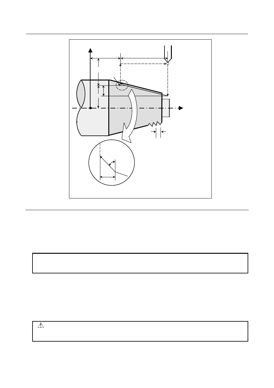
Fig. 4.1.2.2 (a) Taper threading cycle
Explanation
The ranges of thread leads and restrictions related to the spindle speed are the same as for threading with
G32.
The figure of a taper is determined by the coordinates of the cutting end point (A') in the direction of the
length and the sign of the taper amount (address R). For the cycle in the Fig. 4.1.2.2 (a), a minus sign is
added to the taper amount.
NOTE
The increment system of address R for specifying a taper depends on the
increment system for the reference axis. Specify a radius value at R.
- Operations
A taper threading cycle performs the same four operations as a straight threading cycle.
However, operation 1 moves the tool from the start point (A) to the position obtained by adding the taper
amount to the specified coordinate of the second axis on the plane (specified X-coordinate for the ZX
plane) in rapid traverse.
Operations 2, 3, and 4 after operation 1 are the same as for a straight threading cycle.
CAUTION
Notes on this threading are the same as in threading in G32. However, a stop by
feed hold is as follows; Stop after completion of path 3 of threading cycle.