FANUC Series 16i / 18i / 160i / 180i - Model A. Maintenance Manual (B-63005EN/01) - page 11
6. AC SPINDLE (SERIAL INTERFACE)
B-63005EN/01
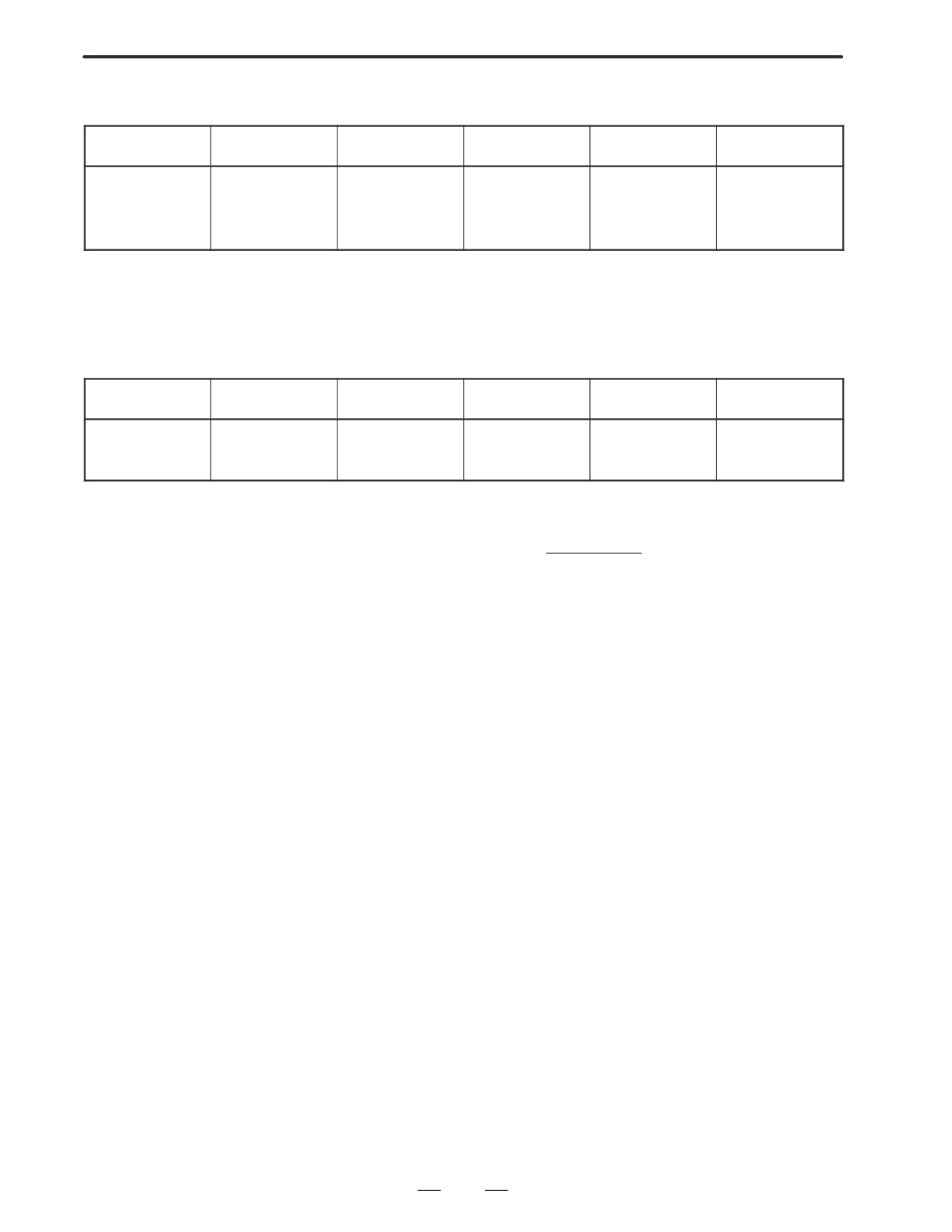
D Displayed parameters
The displayed parameters vary depending on the operation mode.
Spindle position-
Normal
Orientation
Synchronization
Rigid tapping
Cs contour
ing control
operation
control
control
Proportional gain
Proportional gain
Proportional gain
Proportional gain
Proportional gain
Proportional gain
Integral gain
Integral gain
Integral gain
Integral gain
Integral gain
Integral gain
Loop gain
Motor voltage
Loop gain
Loop gain
Loop gain
Loop gain
Motor voltage
Regenerative power
Motor voltage
Motor voltage
Motor voltage
Motor voltage
ZRN gain (%)
ORAR gain (%)
Acceleration/deceleration
ZRN gain
ZRN gain (%)
Shift reference position
Shift spindle stop position
constant (%)
Shift reference position
Shift reference position
Shift reference position
Shift reference position
Note) For the parameter numbers corresponding to the displayed
parameter items, see Section 6.4.5.
D Displayed monitoring
The displayed monitoring items vary depending on the operation mode.
items
Spindle position-
Normal
Orientation
Synchronization
Rigid tapping
Cs contour
ing control
operation
control
control
Motor speed
Motor speed
Motor speed
Motor speed
Motor speed
Motor speed
Feedrate
Spindle speed
Spindle speed
Spindle speed
Spindle speed
Spindle speed
Position deviation S1
Position deviation S1
Position deviation S1
Position deviation S1
Position deviation S1
Position deviation S2
Position deviation Z
Synchronous deviation
Synchronous deviation
Note 1)
|Spindle data|
Motor speed [rpm] +
Max. Motor speed.(* 1)
16383
(*1) Parameter 4020: Main spindleParameter 4196: Subspindle
Note 2) The spindle speed in Cs contour control mode is in degrees/min.
290

6. AC SPINDLE (SERIAL INTERFACE)
B-63005EN/01
6.1.2.4
Spindle monitor screen
SPINDLE MONITOR SCREEN
ALARM
: AL-27(POSITION CODER DIS.)
OPERATION
: Cs AXIS OONTROL
SPINDLE SPEED : 100 DEG/MIN
MOTOR SPEED
: 150 RPM
0
50
100
150
200
LOAD METER (%)
JJJJJ
CONTROL INPUT : ORCM MRDY *ESP
CONTROL OUTPUT : SST SDT ORAR
D Spindle alarm
1: Motor overheated
2: Speed deviation excessive
3: Fuse blow of DC link
4: Fuse blow of AC inputline
5: Fuse blow of DC voltage
7: Excessive speed
9: Heat sink overheat
10: Low voltage of AC input
11: Excess voltage in DC link
12: Excess current in DC link
13: CPU internal data memory error
18: ROM SUM check error
19: U phase current offset excessive
20: V phase current offset excessive
24: Serial data transmission abnormal
25: Serial data transmission stop
26: Cs axis speed detecting signal failure
27: Position coder signal disconnection
28: Cs pos.detect signal disconnection
29: Short time overload
30: Input circuit excess current
31: Speed detecting signal disconnection
32: SLC LSI internal RAM abnormal
33: DC link charging insufficient
34: Parameter abnormal setting
35: Gear ratio data excessive
36: Error counter overflow
37: Speed detecting unit error setting
38: Magnetic sensor signal abnormal
39: Alarm of one revolution signal for Cs axis control is detected
40: Alarm of one revolution signal for Cs axis control is not detected
41: Erroneous detection of the position coder one revolution signal
42: Undetection of the position coder one revolution signal
46: Erroneous detection of the position coder one revolution signal on
threading
47: Abnormal position coder signal
48: Erroneous detection of position coder one revolution signal
291

6. AC SPINDLE (SERIAL INTERFACE)
B-63005EN/01
D Operation
Following 6 modes are available:
a. Normal operation
b. Orientation
c. Synchronous operation
d. Rigid tapping
e. Cs contour cotrol
f. Spindle positioning control
D Load meter
The load meter displays spindle load in a unit of 10%.
1) Load meter[%] +Loadmeterdata
Max.output value
3276
of load meter (*)
(*) PRM 4127: Main
PRM 4274: Sub.
D Control input signal
Max.10 signals those are ON are displayed from the following signals:
TLML
: Torque limit command (low)
SPSL
: Spindle selection signal
TLMH
: Torque limit command (high)
MCFN
: Power line switching
CTH1
: Gear signal 1
SOCN
: Soft start/stop cancel
CTH2
: Gear signal 2
RSL
: Output switching request
SRV
: Spindle reverse rotation
RCH
: Power line state confirm
SFR
: Spindle forward rotation
INDX
: Orientation stop pos.
ORCM
: Spindle orientation
change
MEDY
: Machine ready
ROTA
: Rotation direction of
ARST
: Alarm reset signal
ORCM
*ESP
: Emergency stop
NRRO
: Shor-cut of ORCM
INTG
: Speed integral control
signal
DEFM
: Referencial mode
command
D Control output signals
Max. 10 signals those are ON are displayed from the following signals:
ALM
: Alarm signal
TML5
: Torque limitation
SST
: Speed zero signal
ORAR : Orientation end signal
SDT
: Speed detecting signal
CHP
: Power line switched signal
SAR
: Speed arrival signal
CFIN
: Spindle switch complete
LDT1
: Load detecting signal 1
RCHP
: Output switch signal
LDT2
: Load detecting signal 2
RCFN
: Output switch complete
signal
292
6. AC SPINDLE (SERIAL INTERFACE)
B-63005EN/01
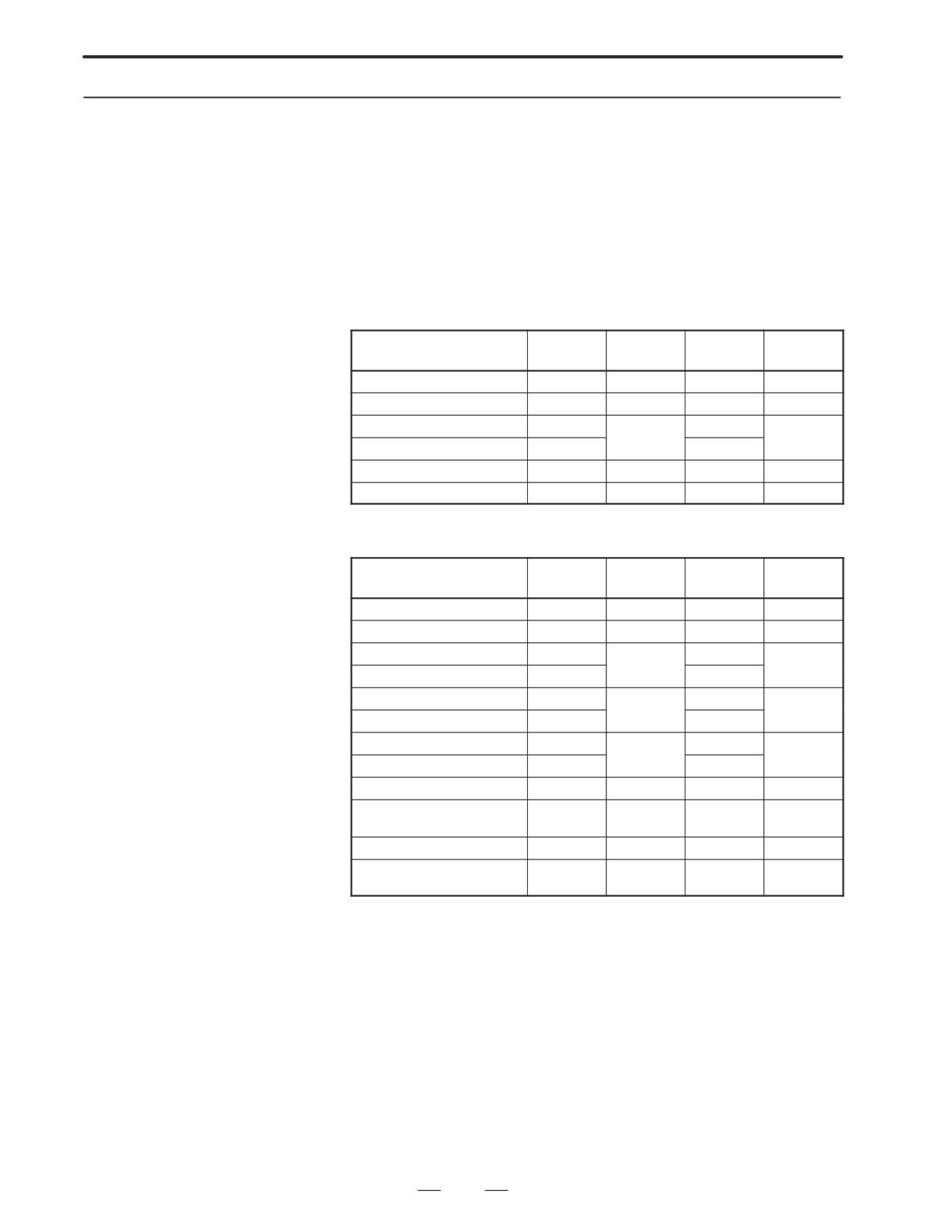
6.1.2.5
Correspondence
between operation mode
and parameters on
spindle tuning screen
D Normal operation mode
S11:
S12:
S21:
S22:
1st Main
1st Sub
2nd Main
2nd Sub
Proportional gain(HIGH)
4040
4206
4040
4206
Proportional gain (LOW)
4041
4207
4041
4207
Integral gain(HIGH)
4048
4048
4212
4212
Integral gain(LOW)
4049
4049
Motor voltage
4083
4236
4083
4236
Regenerative power
4080
4231
4080
4231
D Orientation mode
S11:
S12:
S21:
S22:
1st Main
1st Sub
2nd Main
2nd Sub
Proportional gain(HIGH)
4042
4208
4042
4208
Proportional gain (LOW)
4043
4209
4043
4209
Integral gain(HIGH)
4050
4050
4213
4213
Integral gain(LOW)
4051
4051
Loop gain (HIGH)
4060
4060
4218
4218
Loop gain (MID, HIGH)
4061
4061
Loop gain (MID, LOW)
4062
4062
4219
4219
Loop gain (LOW)
4063
4063
Motor voltage
4084
4237
4084
4237
Gain change upon completion
4064
4220
4064
4220
of orientation
Stop position shift
4077
4228
4077
4228
PC-type orientation stop posi-
4031
4204
4031
4204
tion
293
6. AC SPINDLE (SERIAL INTERFACE)
B-63005EN/01
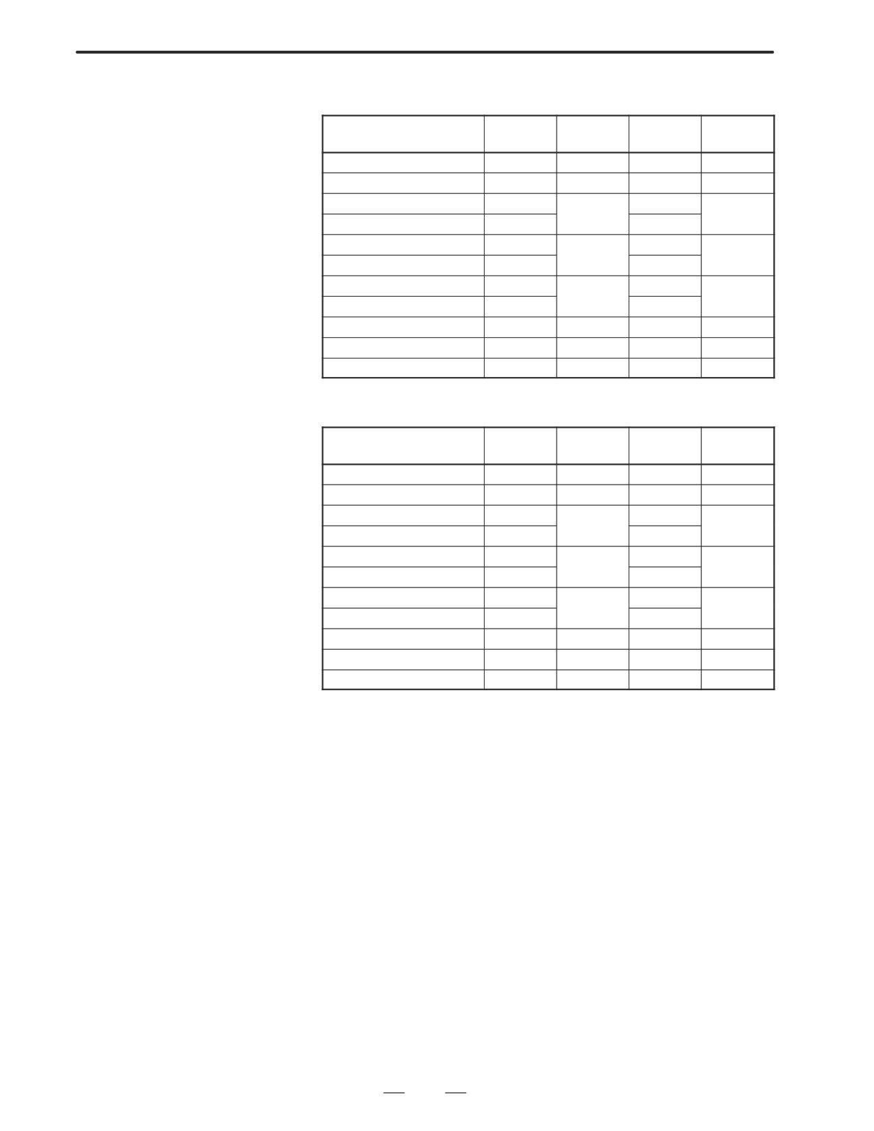
D Synchronization control
Numerals are parameter numbers :
mode
S11:
S12:
S21:
S22:
1st Main
1st Sub
2nd Main
2nd Sub
Proportional gain(HIGH)
4044
4210
4044
4210
Proportional gain(LOW)
4045
4211
4045
4211
Integral gain(HIGH)
4052
4052
4214
4214
Integral gain(LOW)
4053
4053
Position loop gain(HIGH)
4065
4221
4065
4221
Position loop gain(MID,HIGH)
4066
4066
Position loop gain(MID,LOW)
4067
4222
4067
4222
Position loop gain(LOW)
4068
4068
Motor voltage
4085
4238
4085
4238
Acc./Dec. time constant
4032
4032
Shift amount
4034
4034
D Rigid tapping mode
Numerals are parameter numbers :
S11:
S12:
S21:
S22:
1st Main
1st Sub
2nd Main
2nd Sub
Proportional gain(HIGH)
4044
4210
4044
4210
Proportional gain(LOW)
4045
4211
4045
4211
Integral gain(HIGH)
4052
4052
4214
4214
Integral gain(LOW)
4053
4053
Position loop gain(HIGH)
4065
4221
4065
4221
Position loop gain(MID,HIGH)
4066
4066
Position loop gain(MID,LOW)
4067
4222
4067
4222
Position loop gain(LOW)
4068
4068
Motor voltage
4085
4238
4085
4238
ZRN gain %
4091
4239
4091
4239
Grid shift amount
4073
4223
4073
4223
294
6. AC SPINDLE (SERIAL INTERFACE)
B-63005EN/01
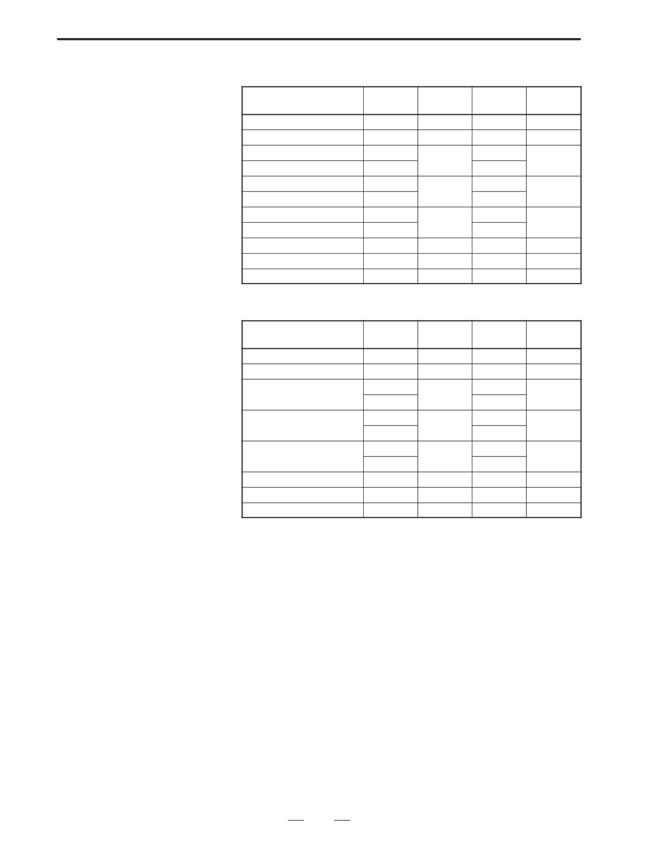
D Spindle contouring
Numerals are parameter numbers :
control mode
(Cs axis control)
S11:
S12:
S21:
S22:
1st Main
1st Sub
2nd Main
2nd Sub
Proportional gain(HIGH)
4046
4046
Proportional gain (LOW)
4047
4047
Integral gain(HIGH)
4054
4054
Integral gain(LOW)
4055
4055
Position loop gain(HIGH)
4069
4069
Position loop gain(MID,HIGH)
4070
4070
Position loop gain(MID,LOW)
4071
4071
Position loop gain(LOW)
4072
4072
Motor voltage
4086
4086
ZRN gain %
4092
4092
Reference position shift
4135
4135
D Spindle positioning
control mode
S11:
S12:
S21:
S22:
1st Main
1st Sub
2nd Main
2nd Sub
Proportional gain(HIGH)
4044
4210
4044
4210
Proportional gain (LOW)
4045
4211
4045
4211
Integral gain(HIGH)
4052
4052
4214
4214
Integral gain(LOW)
4053
4053
Position loop gain(HIGH)
4065
4065
4221
4221
Position loop gain(MID,HIGH)
4066
4066
Position loop gain(MID,LOW)
4067
4067
4222
4222
Position loop gain(LOW)
4068
4068
Motor voltage
4085
4238
4085
4238
ZRN gain %
4091
4239
4091
4239
Reference position shift
4073
4223
4073
4223
295
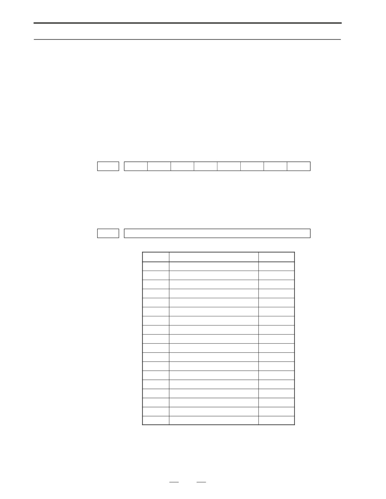
6. AC SPINDLE (SERIAL INTERFACE)
B-63005EN/01
6.1.3
The standard parameters related to each motor model can be set
automatically.
Automatic Setting of
D The specifications for controlling a motor depend on the specifications
Standard Parameters
defined by the machine tool builder. The parameters defined by the
machine tool builder are set as the standard values (initial values) by
this automatic setting function.
Therefore, when performing automatic operation, always set
parameters properly according to the parameter list (parameters
4000 and later).
1. Turn on the power in the emergency stop state.
2. Set bit 7 of parameter 4019 to 1.
#7
#6
#5
#4
#3
#2
#1
#0
4019
LDSP
Bit 7 (LDSP) The parameters for the serial interface spindle are:
0 : Not set automatically.
l 1 : Set automatically.
3. Set a motor model code.
4133
Motor model code
Code
Motor mode
Amplifier
100
a 0.5 (3000/8000min-1)
SPM-2.2
101
a 1 (3000/8000min-1)
SPM-2.2
102
a 1.5 (1500/8000min-1)
SPM-5.5
103
a 2 (1500/8000min-1)
SPM-5.5
104
a 2/1500 (3000/1500min-1)
SPM-5.5
105
a 3 (1500/8000min-1)
SPM-5.5
106
a 6 (1500/8000min-1)
SPM-11
107
a 8 (1500/6000min-1)
SPM-11
108
a 12 (1500/6000min-1)
SPM-15
109
a 15 (1500/6000min-1)
SPM-22
110
a 18 (1500/6000min-1)
SPM-22
111
a 22 (1500/6000min-1)
SPM-26
112
a P8 (750/6000min-1)
SPM-11
113
a P12 (750/6000min-1)
SPM-11
114
a P15 (750/6000min-1)
SPM-15
115
a P18 (750/6000min-1)
SPM-15
116
a P22 (750/6000min-1)
SPM-22
117
a P30 (575/4500min-1)
SPM-22
4. Turn off the power then back on. Then, the parameters are read.
296
6. AC SPINDLE (SERIAL INTERFACE)
B-63005EN/01
6.2
AC SPINDLE
(ANALOG
INTERFACE)
6.2.1
Outline of Spindle
Control
297
6. AC SPINDLE (SERIAL INTERFACE)
B-63005EN/01
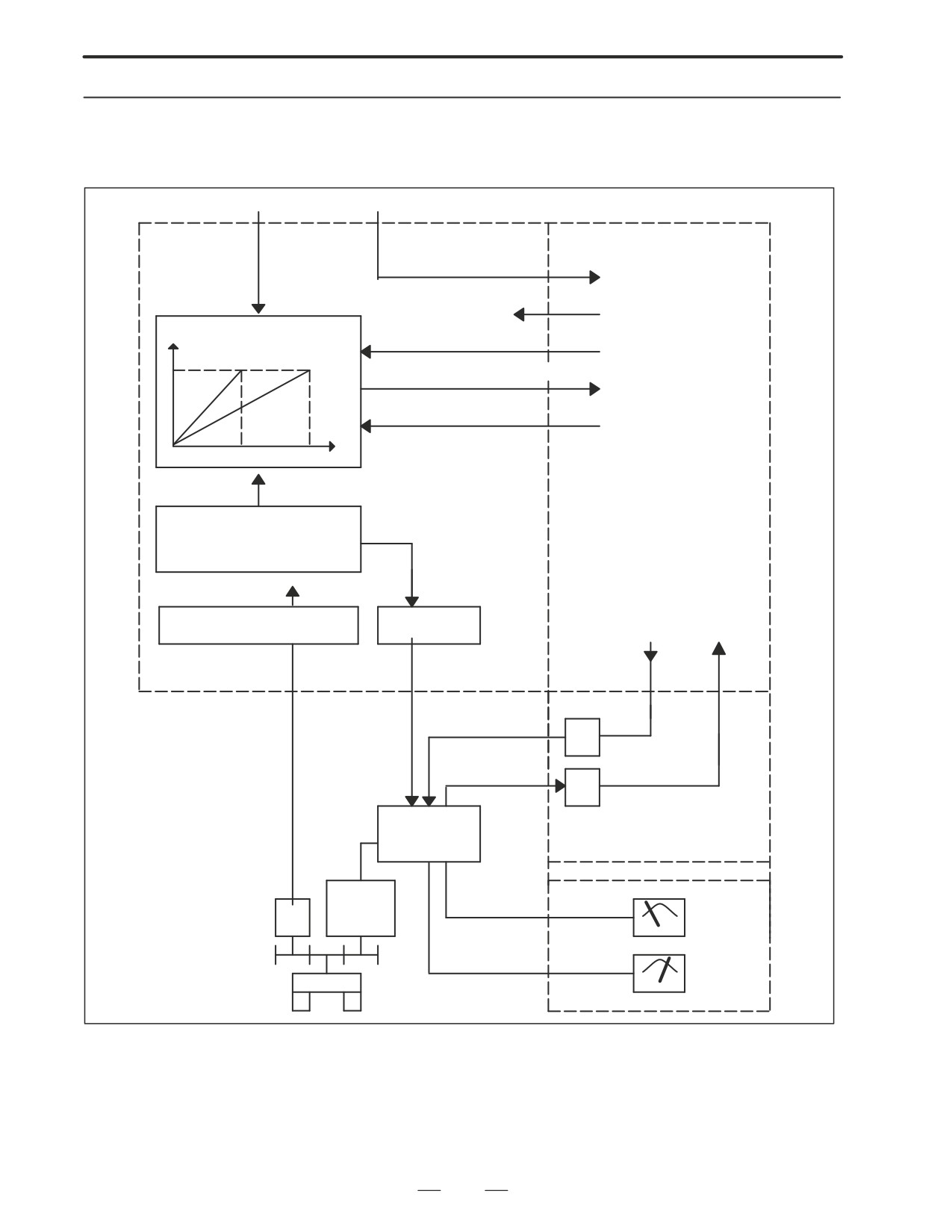
6.2.1.1
Block diagram
S command
M command
PMC
NC
M03 A M05, M06, M19
CW/CCW command,
Spindle speed
orientation, etc.
conversion
FIN
Miscellaneous function end
Motor speed
*SSTP
Spindle stop
Gear 1
Gear 2
GR1O, GR2O, GR3O
Gear selection (16M/18M)
GR1, GR2
Gear information (16T/18T)
S
Maximum spindle speed and other
parameters
PRM 3714 to 3743, 3735, 3736,
3751 and 3752 (M series)
PRM 3741 to 3744 (T series)
*ESP, MRDY
SAR, LDT
SFR, SRV
SST, ORAR
ORCM, TLM
SDT, ALM
Position coder interface
D/A converter
PRM 3730 (gain)
PRM 3731 (offset)
DV
SVC
RV
I/O card or I/O unit
Spindle amplifier
Operator’s panel
Spindle
PC
motor
Load meter
LM
Speed meter
Spindle
SM
298
6. AC SPINDLE (SERIAL INTERFACE)
B-63005EN/01
6.2.1.2
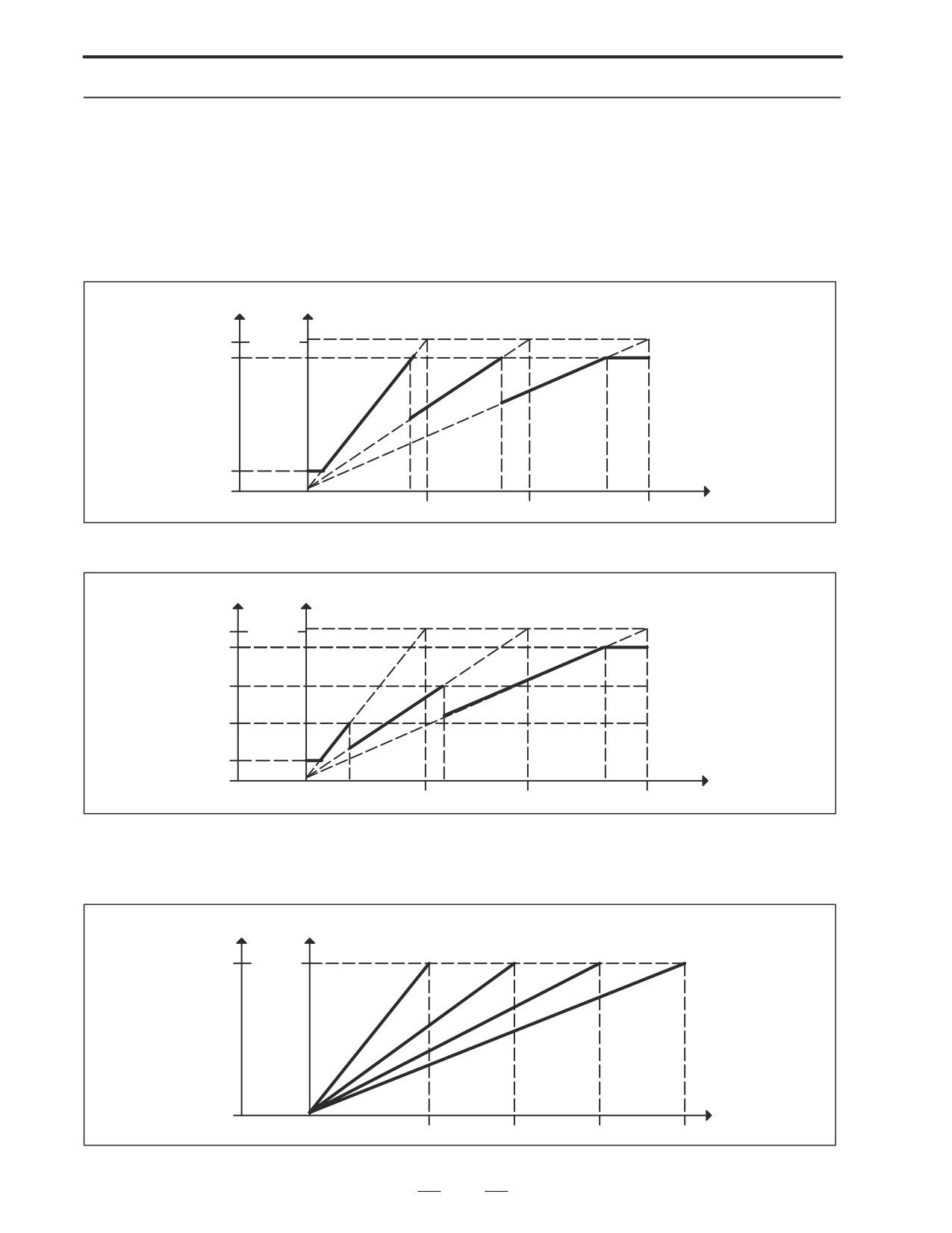
Calculation of S analog
voltage and related
parameters
[M series]
1
Gear change method A (bit 2 of parameter 3705 = 0)
SVC
Motor speed
Gear 1
Gear 2
Gear 3
(4095) 10V
Max
PRM 3736
PRM
3742
PRM
3743
(RPM)
PRM 3735
0V
S code
0
PRM 3741
PRM 3742
PRM 3743
(RPM)
2
Gear change method B (bit 2 of parameter 3705 = 1)
SVC Motor speed
Gear 1
Gear 2
Gear 3
Max
(4095) 10V
PRM 3736
PRM 3752
PRM 3751
PRM 3735
0V
S code
0
PRM 3741
PRM 3742
PRM 3743
(RPM)
[T series]
Constant surface speed control
SVC Motor speed
Gear 1
Gear 2
Gear 3
Gear 4
(4095) 10V
Max
0V
S code
0
PRM 3741
PRM 3742
PRM 3743
PRM 3744
(RPM)
299
6. AC SPINDLE (SERIAL INTERFACE)
B-63005EN/01
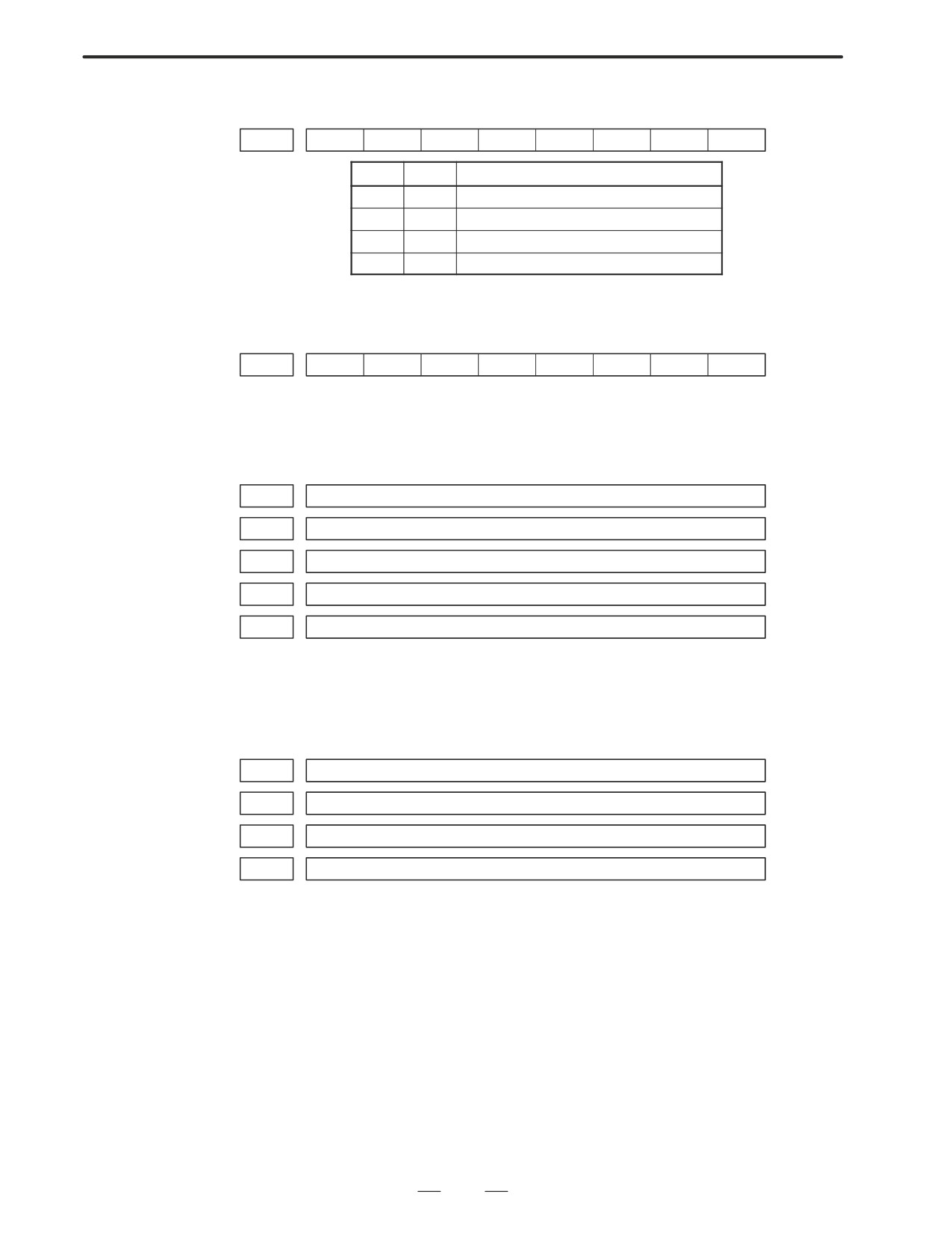
#7
#6
#5
#4
#3
#2
#1
#0
3706
TCW
CWM
TCW
CWM
Sign of output voltage
0
0
Analog voltage (+) with both M03 and M04
0
1
Analog voltage (-) with both M03 and M04
1
0
(+) with M03, (-) with M04
1
1
(-) with M03, (+) with M04
[M series]
#7
#6
#5
#4
#3
#2
#1
#0
3705
SGB
SGB
Spindle speed set when gear change is performed is:
0 : Maximum speed for each gear.
1 : Set by respective parameters. (Parameters 542, 543, 585, 586)
3741
Max. spindle speed of gear 1 (1 to 9999) [rpm]
3742
Max. spindle speed of gear 2 (1 to 9999) [rpm]
3743
Max. spindle speed of gear 3 (1 to 9999) [rpm]
3736
Upper limit of the output to the spindle motor
3735
Lower limit of the output to the spindle motor
Setting +Spindlespeed(upperlimitńlowerlimit)
4095
Max. spindle speed
[T series]
3741
Max. spindle speed of gear 1 (1 to 9999) [rpm]
3742
Max. spindle speed of gear 2 (1 to 9999) [rpm]
3743
Max. spindle speed of gear 3 (1 to 9999) [rpm]
3744
Max. spindle speed of gear 4 (1 to 9999) [rpm]
300
6. AC SPINDLE (SERIAL INTERFACE)
B-63005EN/01
6.2.1.3
Tuning S analog voltage
(D/A converter)
(1) For M series, change the upper and lower limits as follows:
⋅ When gear change method A is used: Parameter 3736 = 4095,
parameter 3735 = 0
⋅ When gear change method B is used: Parameter 3751 = 4095,
parameter 3735 = 0
. For T series, these changes are not required.
(2) Tuning the D/A converter offset
Specify zero as the spindle speed. Then, by using a digital multimeter,
adjust the following parameter so that the voltage at the test pin DA2
on the spindle amplifier printed circuit board is 0 mV.
1
For M series
S0; (Specify the command by MDI operation, then press the cycle start button.)
2
For T series (in case of G-code system A)
G97 S0;
(Specify the command by MDI in the same manner as for M series.)
3731
Spindle speed (D/A converter) offset compensation value
(3) Tuning the D/A converter gain
Specify the maximum spindle speed of gear 1. Then, by using a digital
multimeter, adjust the following parameter so that the voltage at the
test pin DA2 on the spindle amplifier printed circuit board is 10.0 V.
1
For M series
Sxxxx ;
(xxxx is the value set in parameter 3741.)
(Specify the command by MDI operation, then press the cycle start button.)
3741
Max. spindle speed of gear 1 (1 to 9999) [rpm]
2
For T series (in case of G-code system A)
G97 Sxxxx ;
(xxxx is the value set in parameter 3741.)
(Specify the command by MDI operation, then press the cycle start button.)
3741
Max. spindle speed of gear 1 (1 to 9999) [rpm]
. Usually a voltage is output from the D/A converter by only
executing an S command. However, the clockwise rotation
command (M03) may be required on some machines.
301
6. AC SPINDLE (SERIAL INTERFACE)
B-63005EN/01
(4) If the output voltage is not correct, perform the following calculation,
and change the value of parameter 3730 to adjust the gain of the D/A
converter:
10V
Setting +
(Current value of PRM 3730)
Measured voltage
(5) Execute an S command again and confirm that the output voltage is
correct.
.Restore the original parameter values.
302
B-63005EN/01
7.TROUBLESHOOTING
TROUBLESHOOTING
7
This chapter describes troubleshooting procedure.
7.1
CORRECTIVE ACTION FOR FAILURES
304
7.2
NO MANUAL OPERATION NOR AUTOMATIC . . 306
OPERATION CAN BE EXECUTED
7.3
JOG OPERATION CANNOT BE DONE
310
7.4
HANDLE OPERATION (MPG)
CANNOT BE DONE
314
7.5
AUTOMATIC OPERATION CANNOT BE DONE . . 317
7.6
CYCLE START LED SIGNAL HAS
TURNED OFF
325
7.7
NO DISPLAY APPEARS AT POWER-UP
327
7.8
ALARM 85 TO 87
(READER/PUNCHER INTERFACE ALARM)
329
7.9
ALARM 90(REFERENCE POSITION
RETURN IS ABNORMAL)
336
7.10
ALARM 300 (REQUEST FOR REFERENCE
POSITION RETURN)
338
7.11
ALARM 417
(DIGITAL SERVO SYSTEM IS ABNORMAL)
339
7.12
ALARM 704 (SPINDLE SPEED FLUCTUATION
DETECTION ALARM)
340
7.13
ALARM 749 (SERIAL SPINDLE
COMMUNICATION ERROR)
341
7.14
ALARM 750 (SPINDLE SERIAL LINK
CANNOT BE STARTED)
342
7.15
ALARM 700 (OVERHEAT AT CONTROL SIDE) . . 344
7.16
ALARM 900 (ROM PARITY ERROR)
345
7.17
ALARM 910, 911 (SRAM PARITY ERROR)
347
7.18
ALARM 912 TO 919 (DRAM PARITY ERROR) . . . 349
7.19
ALARM 920, 921
(WATCHDOG OR RAM PARITY)
350
7.20
ALARM 924 (SERVO MODULE
MOUNTING ERROR)
352
7.21
ALARM 930 (CPU ERROR)
353
7.22
ALARM 950 (PMC SYSTEM ALARM)
354
7.23
ALARM 951 (PMC-RC WATCHDOG ALARM) . . . 357
7.24
ALARM 972 (NMI ALARM)
358
7.25
ALARM 973 (NMI ALARM BY
UNKNOWN CAUSE)
359
303

7. TROUBLESHOOTING
B-63005EN/01
When a failure occurs, it is important to correctly grasp what kind of
7.1
failure occured and take appropriate action, to promptly recover the
CORRECTIVE
machine.
ACTION FOR
Check for the failure according to the following procedure :
FAILURES
With what
When?
What failure?
operation?
Grasp the kind of failure
↓
Appropriate action
↓
Recovery
7.1.1
Investigating the
(1) When and how many times (frequency of occurrences)
Conditions under
(2) With what operation
(3) What failure occurred
which Failure Occurred
1
When did the failure occur?
Date and time?
Occurred during operation? (how long was the operation?)
Occurred when the power was turned on?
Was there any lightening surge, power failure, or other disturbances to
the power supply?
How many times has it occurred
Only once?
Occurred many times ? (How many times per hour, per day, or per
month?)
2
With what operation did it occur ?
What was the NC mode when the failure occurred?
Jog mode/memory operation mode /MDI mode /reference position
return mode
If during program operation,
1) Where in the program ?
2) Which program No. and sequence No. ?
3) What program ?
4) Occurred during axial movement ?
5) Occurred during the execution of an M/S/T code ?
6) Failure specific to the program ?
Does the same operation cause the same failure ?
(Check the repeatability of the failure.)
Occurred during data input/output ?
<Feed axes and spindles>
For a failure related to feed axis servo
1) Occurred at both low feedrate and high feedrate ?
2) Ocurred only for a certain axis ?
304
B-63005EN/01
7.TROUBLESHOOTING
For a failure related to spindles
When did the failure occur ? (during power-on, acceleration,
deceleration, or constant rotation)
3
What failure occurred ?
Which alarm was displayed on the alarm display screen on the CRT?
(Check the axis along which an alarm has occurred for alarms 300 to
599.)
For alarm 350 : Examine diagnostic 202
For alarm 351 : Examine diagnostic 203
For alarm 414 : What does diagnostic display 200,201,204
indicate ?
For alarm 751 or 761
: Which spindle alarm is indicated ?
(indicated by AL-XX (XX is a number))
Is the screen correct ?
If machining dimensions are incorrect
1) How large is the error ?
2) Is the position display on the CRT correct ?
3) Are the offsets correct ?
4
Other information
⋅
Is there noise origin around machine?
If the failure has not occurred frequently, the cause may be external
noise to the power supply or inductive noise on machinery cables.
Operate other machines connected to the same power line and see
if noise come from the relays or compressors.
⋅
Is it taken any countermeasure for noise in machine side?
⋅
Check the following for the input power supply voltage :
1) Is there variation in the voltage ?
2) Are the voltages different depending on the phase ?
3) Is the standard voltage supplied ?
⋅
How high is the ambient temperature of the control unit?
(0_C to 45_C during operation)
Refer to manual about noise.
⋅
Has excessive vibration been applied to the control unit?
(0.5 G or less during operation)
5
When you contact our service center, specify the following items :
1) Name of the NC unit
2) Name of the machine tool builder and type of machine
3) Software series/version of the NC
4) Specifications of the servo amplifier and motor
(for a failure related to the servo)
5) Specifications of the spindle amplifier and spindle motor
(for a failure related to a spindle)
See the drawing issued by the machine tool builder for the locations
of the NC unit and servo/spindle amplifiers.
We use the following specification codes :
Servo /spindle amplifier : A06B-VVVV-HVVV
Servo/spindle amplifier
: A06B-VVVV-BVVV
(V represents a number)
305
7. TROUBLESHOOTING
B-63005EN/01
7.2
NO MANUAL OPERA-
TION NOR AUTOMAT-
IC OPERATION CAN
BE EXECUTED
Points
(1) Execute the following procedure when no manual nor automatic
operation is done
(2) Check whether position display shows correct position
(3) Check CNC status display
(4) Check CNC internal status using diagnostic function
Causes and
Countermeasures
1. Position display
(1) Check CNC status display (Refer to Section
1.9 NC STATUS
(relative, absolute,
DISPLAY for detail.)
machine coordinate)
(a) Emergency stop status (Emergency stop signal is turned on)
does not change
If status display shows
EMG
the emergency stop signal is input.
Check the following signal using the PMC’s diagnostic function
(PMCDGN).
1) When built-in I/O card is used.
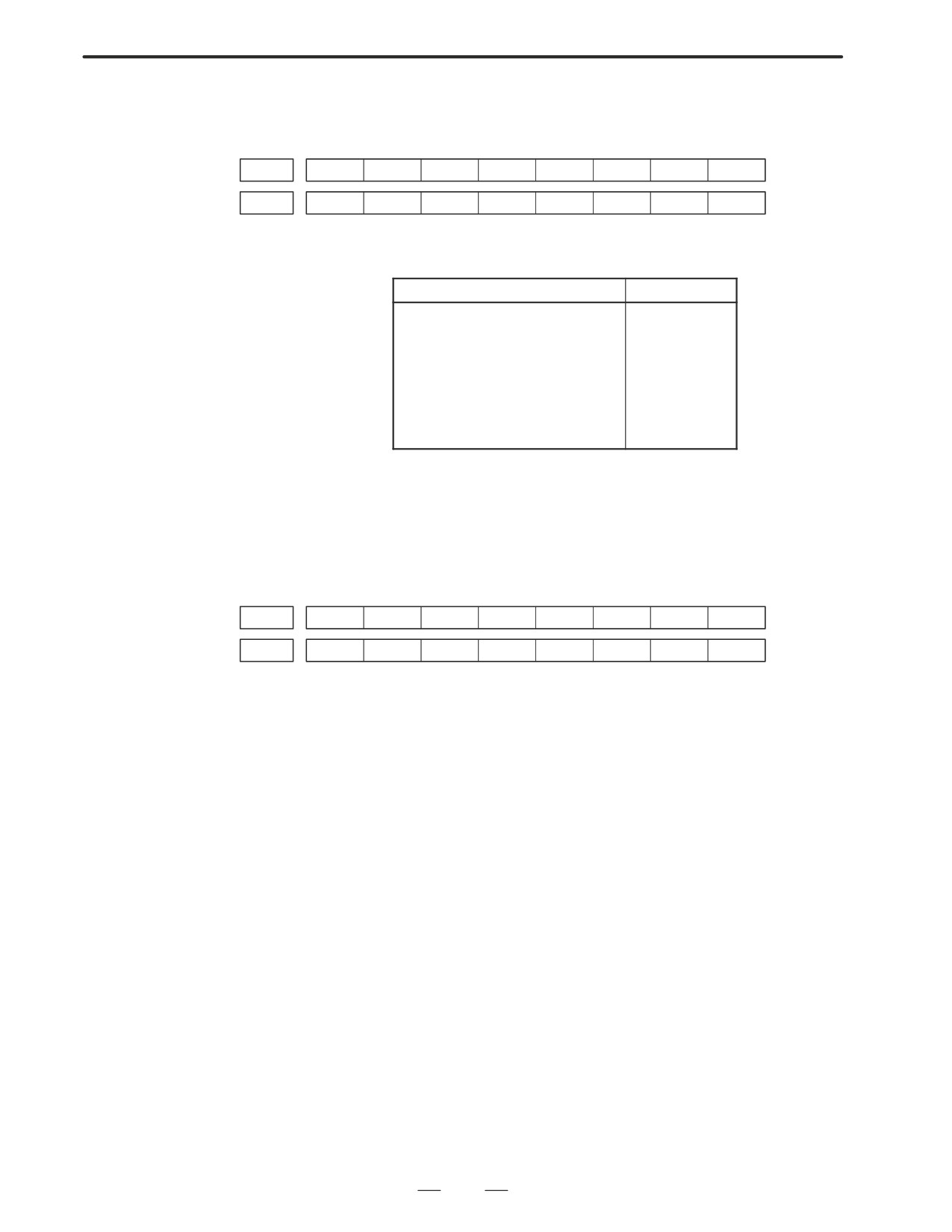
#7
#6
#5
#4
#3
#2
#1
#0
X1008
*ESP
G0008
*ESP
ESP=0 indicates that emergency stop signal is input.
2) When built-in I/O card is not used.
#7
#6
#5
#4
#3
#2
#1
#0
X1008
*ESP
G0008
*ESP
ESP=0 indicates that emergency stop signal is input.
(b) It is a reset status
When RESET is displayed, any of a reset is functioned. Check the
following signal using the PMC’s diagnostic funciton
(PMCDGN).
1) An input signal from the PMC functions
#7
#6
#5
#4
#3
#2
#1
#0
G0008
ERS
RRW
When ERS is 1, external reset signal is input.
When RRW is 1, reset & rewing signal is input.
2) RESET key on the MDI keyboard functions
When the signals in 1) are 0,
RESET
key may be functioning.
Check the contact of
RESET
key using a tester.
When it is abnormal, change the keyboard.
306
B-63005EN/01
7.TROUBLESHOOTING
(c) Confirm the status of modes
Operation mode status is displayed on the lower part of CRT as
follows :
If nothing is displayed, mode select signal is not input. Check mode
select signal using PMC’s diagnostic function (PMCDGN).
For details, refer to section 1.7 STATUS DISPLAY.
(Example of display)
JOG : Manual operation (JOG) mode
HND : Manual handle (MPG) mode
MDI : Manual data input (MDI) mode
MEM : Automatic operation (Memory) mode
EDIT: EDIT (Memory edit) mode
<Mode select signal>
#7
#6
#5
#4
#3
#2
#1
#0
G0043
MD4
MD2
MD1
↓
↓
↓
Manual operation (JOG) mode
1
0
1
Manual handle (MPG) mode
1
0
0
Manual data input (MDI) mode
0
0
0
Automatic operation (Memory) mode
0
0
1
EDIT (Memory edit) mode
0
1
1
(2) Check diagnostic data 000 to 025 of the CNC Check an item for which
1 is displayed
No. Message
Display
000
WAITING FOR FIN SIGNAL
: 0
001
MOTION
: 0
002
DWELL
: 0
a.003
IN-POSITION CHECK
: 0
004
FEEDRATE OVERRIDE 0%
: 0
b.005
INTERLOCK / START LOCK
: 1 (Example)
006
SPINDLE SPEED ARRIVAL CHECK
: 0
010
PUNCHING
: 0
011
READING
: 0
012
WAITING FOR (UN) CLAMP
: 0
c.013
JOG FEEDRATE OVERRIDE 0%
: 0
d.014
WAITING FOR RESET, ESP, RRW OFF
: 0
015
EXTERNAL PROGRAM NUMBER SEARCH
: 0
Items with a to d relate with manual and automatic operation and its
detail is shown below.
307
7. TROUBLESHOOTING
B-63005EN/01
a. In-position check is
It shows that positioning is not yet completed. Check the contents of the
being done
following diagnostic number. (It is 1 in the following condition)
DGN 0300
Position Error
>PARAM 1826
In-positio width
1) Check the parameters according to the parameter list.
1825
Servo loop gain per axis
(Normal : 3000)
2) Servo system may be abnormal. Refer to servo alarm 400, 410, and
411.
b. Interlock or start lock
There are a plural interlock signals. Check at first which interlock signal
signal is input
is used by the machine tool builder at the parameters shown below.
#7
#6
#5
#4
#3
#2
#1
#0
3003
DIT
ITX
ITL
#0 ITL=0 shows interlock signal *IT is effective. To 1)
#2 ITX=0 shows interlock signal *ITn is effective. To 2)
#3 DIT=0 shows interlock signal "MITn is effective. To 3)
Check state of effective interlock signals using the diagnostic function
(PMCDGN) of the PMC.
1)
Interlock signal (*IT) is input.
#7
#6
#5
#4
#3
#2
#1
#0
G0008
*IT
*IT=0 shows that interlock signal is input.
2)
Axis interlock signal (*ITn) is input.
#7
#6
#5
#4
#3
#2
#1
#0
G0130
*IT8
*IT7
*IT6
*IT5
*IT4
*IT3
*IT2
+IT1
*ITn=0 shows interlock signal is input.
3)
Interlock signal per axis and direction (+/- MITn) is input.
#7
#6
#5
#4
#3
#2
#1
#0
G0132
+MIT4
+MIT3
+MIT2
+MIT1
G0134
-MIT4
-MIT3
-MIT2
-MIT1
"MITn=1 shows interlock signal per axis and direction is input.
308
B-63005EN/01
7.TROUBLESHOOTING
c. Jog feedrate override is
Check the signals using PMC’s diagnostic function (PMCDGN)
0%
#7
#6
#5
#4
#3
#2
#1
#0
G0010
*JV7
*JV6
*JV5
*JV4
*JV3
*JV2
*JV1
*JV0
G0011
*JV15
*JV14
*JV13
*JV12
*JV11
*JV10
*JV9
*JV8
When the override is 0% all bits of the above address becomes
1111
1111 or 0000
0000.
*JV15
JV0
Override
1111 1111 1111 1111
0.00%
1111 1111 1111 1110
0.01%
:
:
1101 1000 1110 1111
100.00%
:
:
0000 0000 0000 0001
655.34%
0000 0000 0000 0000
0.00%
d. NC is in a reset state
In this case, RESET is also displayed on the status display. Check it using
the procedure of 1 above.
2. When machine
(1) Machine lock signal (MLK) is input.
coordinate value does
not update on position
display
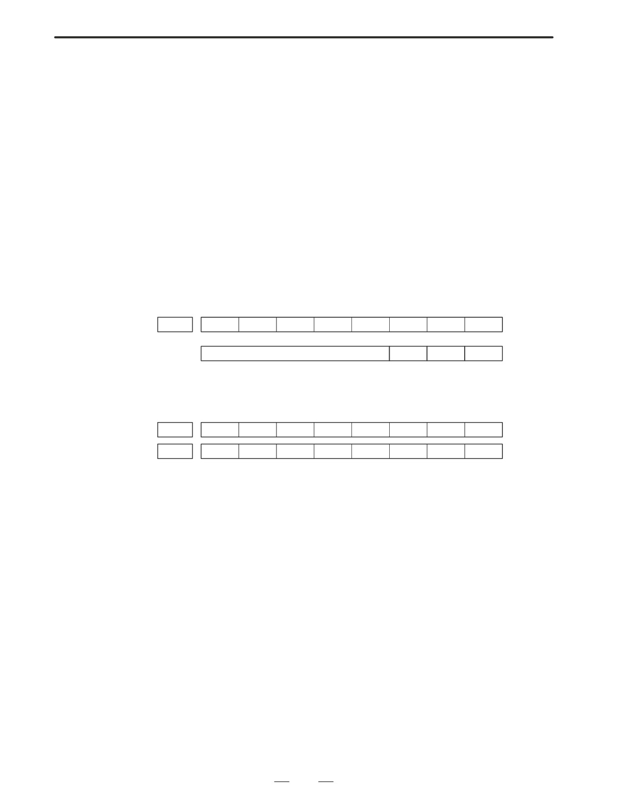
#7
#6
#5
#4
#3
#2
#1
#0
G0044
MLK
G0108
MLK8
MLK7
MLK6
MLK5
MLK4
MLK3
MLK2
MLK1
MLK : All axes machine lock
MLKn : Each axis machine lock
When the signal is 1, the corresponding machine lock signal is input.
309
7. TROUBLESHOOTING
B-63005EN/01
7.3
JOG OPERATION
CANNOT BE DONE
Points
(1) Check whether position display is operating.
(2) Check CNC status display.
(3) Check internal status using Diagnostic funciton.
Causes and Remedies
1. Position display
(1) Check mode selection status (JOG mode is not selected).
(relative, absolute,
When status display shows JOG, it is normal.
machine cooordinate)
When status display does not show JOG, mode select signal is not
does not change
selected correctly. Confirm the mode select signal using PMC’s
diagnostic function (PMCDGN).
<Mode select signal>
#7
#6
#5
#4
#3
#2
#1
#0
G0043
MD4
MD2
MD1
↓
↓
↓
Manual operation (JOG) mode
1
0
1
(2) Feed axis and direction select signal is not input Check the signal using
PMC’s diagnostic function (PMCDGN).
#7
#6
#5
#4
#3
#2
#1
#0
G0100
+J8
+J7
+J6
+J5
+J4
+J3
+J2
+J1
G0102
-J8
-J7
-J6
-J5
-J4
-J3
-J2
-J1
Example)
When +X button is pressed on the operator’s panel, signal+J1 turns to
1.
This signal is effected at its rise. If axis selection signal is input before
JOG mode is selected, axis movement does not occur. Turn the signal
to off, then on.
310
B-63005EN/01
7.TROUBLESHOOTING
(3) Check CNC’s diagnostic function 000 to 015. Check the items for
which 1 is displayed at right side.
No. Message
Display
000
WAITING FOR FIN SIGNAL
: 0
001
MOTION
: 0
002
DWELL
: 0
a.
003
IN-POSITION CHECK
: 0
004
FEEDRATE OVERRIDE 0%
: 0
b.
005
INTERLOCK / START LOCK
: 1(Example)
006
SPINDLE SPEED ARRIVAL CHECK
: 0
010
PUNCHING
: 0
011
READING
: 0
012
WAITING FOR (UN) CLAMP
: 0
c.
013
JOG FEEDRATE OVERRIDE 0%
: 0
d.
014
WAITING FOR RESET, ESP, RRW OFF
: 0
015
EXTERNAL PROGRAM NUMBER SEARCH
: 0
Items with a to d relate with manual and automatic operation and its
detail is shown below.
311
7. TROUBLESHOOTING
B-63005EN/01
a. In-position check is
It shows that positioning is not yet completed. Check the contents of the
being done
following diagnostic number. (It is 1 in the following condition)
DGN 0300
Position Error
>PARAM 1826
In-positio width
1) Check the parameters according to the parameter list.
1825
Servo loop gain per axis
(Normal : 3000)
2) Servo system may be abnormal. Refer to servo alarm 400, 410, and
411.
b. Interlock or start lock
There are a plural interlock signals. Check at first which interlock signal
signal is input
is used by the machine tool builder at the parameters shown below.
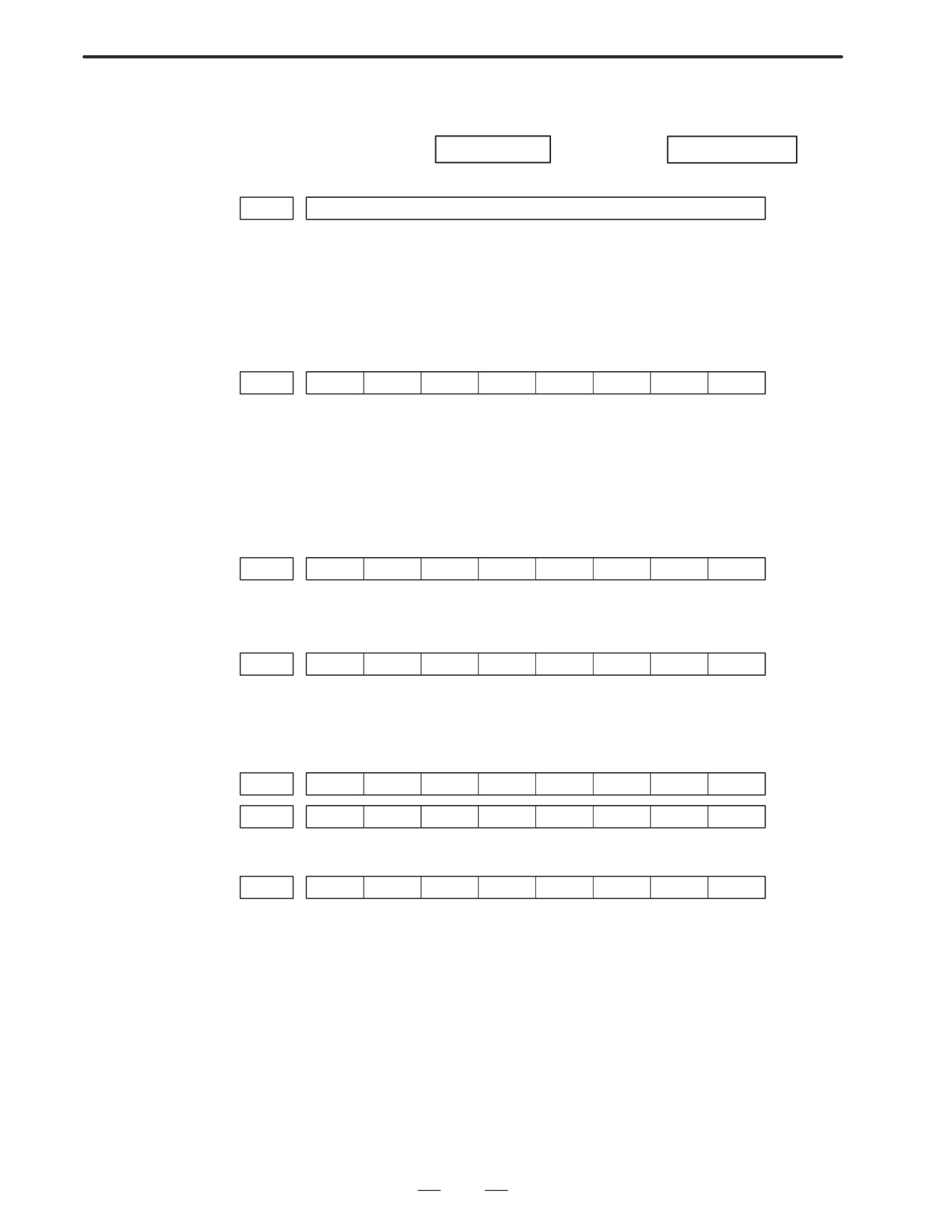
#7
#6
#5
#4
#3
#2
#1
#0
PARAM
3003
DIT
ITX
ITL
#0 ITL=0 shows interlock signal *IT is effective. To 1)
#2 ITX=0 shows interlock signal *ITn is effective. To 2)
#3 DIT=0 shows interlock signal "MITn is effective. To 3)
Check state of effective interlock signals using the diagnostic function
(PMCDGN) of the PMC.
1) Interlock signal (*IT) is input.
#7
#6
#5
#4
#3
#2
#1
#0
G0008
*IT
*IT=0 shows that interlock signal is input.
2) Axis interlock signal (*ITn) is input.
#7
#6
#5
#4
#3
#2
#1
#0
G0130
*IT8
*IT7
*IT6
*IT5
*IT4
*IT3
*IT2
+IT1
*ITn=0 shows interlock signal is input.
3) Interlock signal per axis and direction (+/- MITn) is input
⋅ M series
#7
#6
#5
#4
#3
#2
#1
#0
G0132
+MIT4
+MIT3
+MIT2
+MIT1
G0134
-MIT4
-MIT3
-MIT2
-MIT1
⋅ T series
#7
#6
#5
#4
#3
#2
#1
#0
X0004
-MIT2
+MIT2
-MIT1
+MIT1
"MITn=1 shows interlock signal per axis and direction is input.
* For the T series, "MITn is valid only for manual operation.
312
B-63005EN/01
7.TROUBLESHOOTING
c. Jog feedrate override is
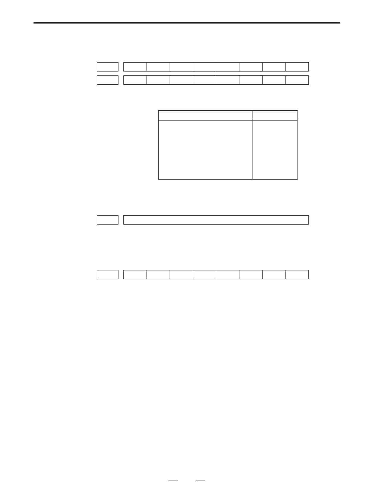
Check the signals using PMC’s diagnostic function (PMCDGN)
0%
#7
#6
#5
#4
#3
#2
#1
#0
G0010
*JV7
*JV6
*JV5
*JV4
*JV3
*JV2
*JV1
*JV0
G0011
*JV15
*JV14
*JV13
*JV12
*JV11
*JV10
*JV9
*JV8
When the override is 0% all bits of the above address becomes
1111
1111 or 0000
0000.
*JV15
JV0
Override
1111 1111 1111 1111
0.00%
1111 1111 1111 1110
0.01%
:
:
1101 1000 1110 1111
100.00%
:
:
0000 0000 0000 0001
655.34%
0000 0000 0000 0000
0.00%
d. NC is in a reset state
In this case, RESET is also displayed on the status display. Check it using
the procedure of 1 above.
(4) Jog feed rate setting (Parameter) is not correct.
1423
Jog feedrate per axis
(5) Manual feed per revolution is selected ( T series)
This funciton feeds an axis synchronized with spindle rotation and
whether this function is used or not is selected by the following
parameter:
#7
#6
#5
#4
#3
#2
#1
#0
1402
JRV
#4 (JRV)
0 : Jog feed is of feed per minute
1 : Jog feed is of feed per revolution
(a) When parameter JRV is set to 1, feed rate of the axis is calculated
by synchronizing with rotation of the spindle. Therefore, rotate the
spindle.
(b) If the axis does not move even when the spindle is rotated, check
the detector of the spindle (position coder) and the cable between
the position coder and the CNC if it is short-circuited or
ungrounded.Refer to 2.4 for connection diagram.
313
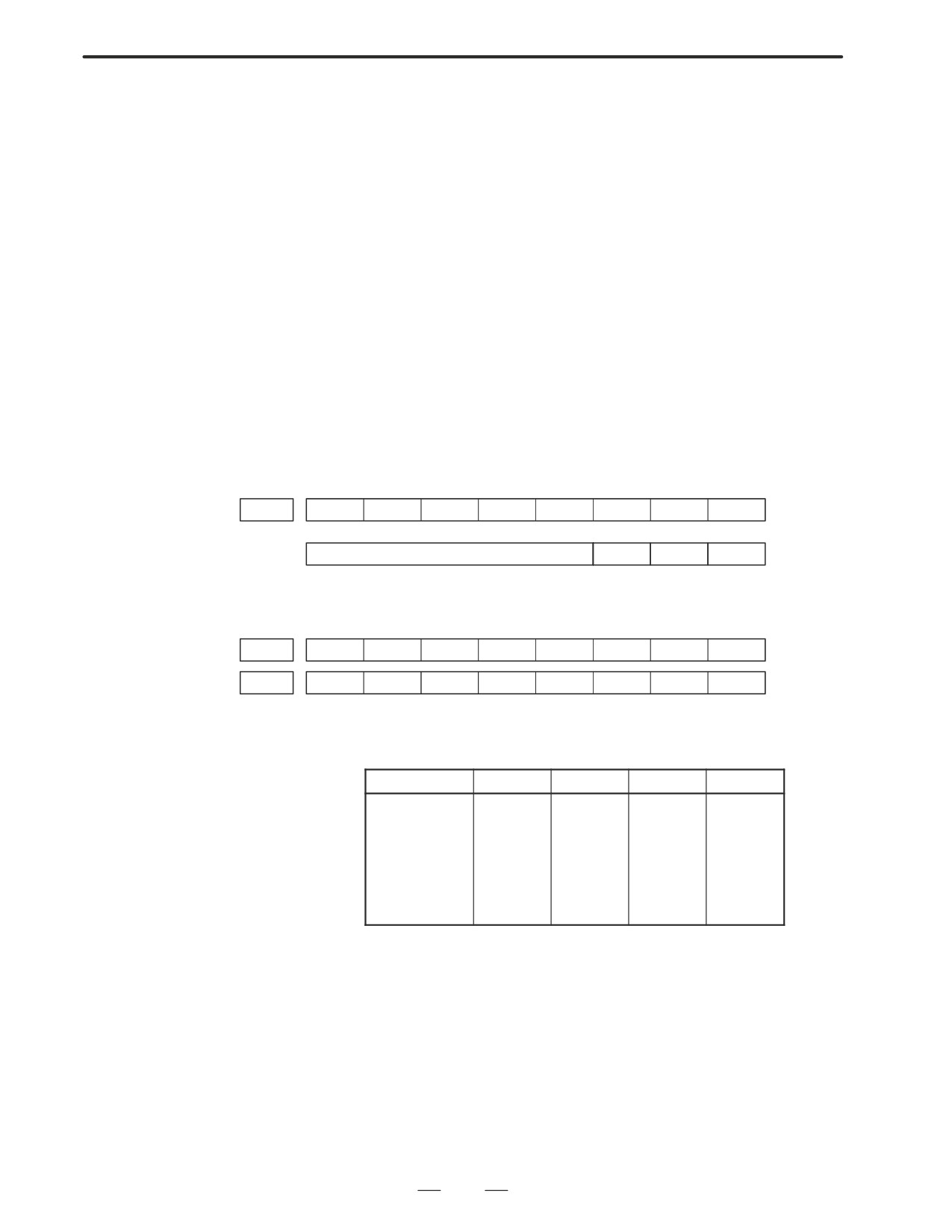
7. TROUBLESHOOTING
B-63005EN/01
7.4
HANDLE OPERATION
CANNOT BE DONE
Points
(1) Check another manual operation (JOG) is accepted.
(2) Check CNC status display.
Causes and
Countermeasure
1
JOG operation is not
Consult with item 8.3 and 8.4.
acceptable, either
2
When only handle
(1) Check CNC status display at lower left corner of the CRT.
operation (MPG) cannot
(Refer to 1.7 STATUS DISPLAY for details)
be done
When the status display shows HND, mode selection is correct.
If it is not HND, mode select signal is not input correctly. Check the
mode select signal using the PMC’s diagnostic function(PMCDGN).
#7
#6
#5
#4
#3
#2
#1
#0
G0043
MD4
MD2
MD1
↓
↓
↓
Manuale handle mode
1
0
0
(2) Manual handle feed axis select signal is not input.
Check the signals using PMC’s diagnostic function (PMCDGN).
#7
#6
#5
#4
#3
#2
#1
#0
G0018
HS2D
HS2C
HS2B
HS2A
HS1D
HS1C
HS1B
HS1A
G0019
HS3D
HS3C
HS3B
HS3A
When axis select switch for manual handle feed is selected on the
machine operator’s panel, if the signals are input as follows, it is
normal.
Selected axis
HSnD
HSnC
HSnB
HSnA
no selection
0
0
0
0
1st axis
0
0
0
1
2nd axis
0
0
1
0
3rd axis
0
0
1
1
4th axis
0
1
0
0
5th axis
0
1
0
1
6th axis
0
1
1
0
7th axis
0
1
1
1
8th axis
1
0
0
0
In the above table, n is the number of the manual pulse generator
(MPG) and up to 3 MPGs can be used.
A feed axis is selected by 4-bit code of A to D.
314
B-63005EN/01
7.TROUBLESHOOTING
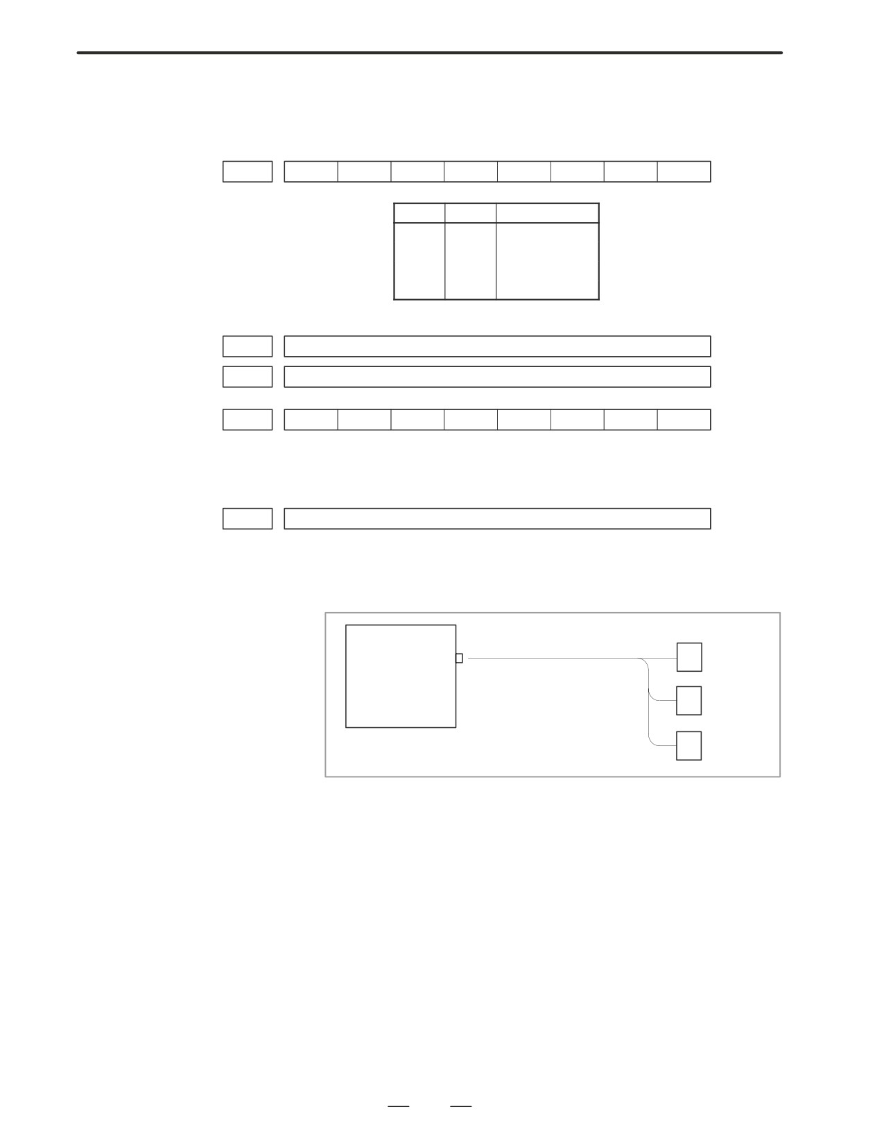
(3) Manual handle feed multiplication is not correct
Check the following signals using PMC’s PCDGN. Also confirm the
following parameters based on the parameter list.
#7
#6
#5
#4
#3
#2
#1
#0
G0019
MP2
MP1
↓
↓
MP2
MP1
Multiplication
0
0
1
1
0
10
0
1
m
1
1
n
7113
Magnification of handle feed m(1 to 127)
7114
Magnification of handle feed n(1 to 1000)
#7
#6
#5
#4
#3
#2
#1
#0
7102
HNGx
#0(HNGx) Direction of MPG and travel of machine
0 : same direction
1 : reverse direction
7110
No. of MPGs used
(1 to 3)
(4) Checking manual pulse generator
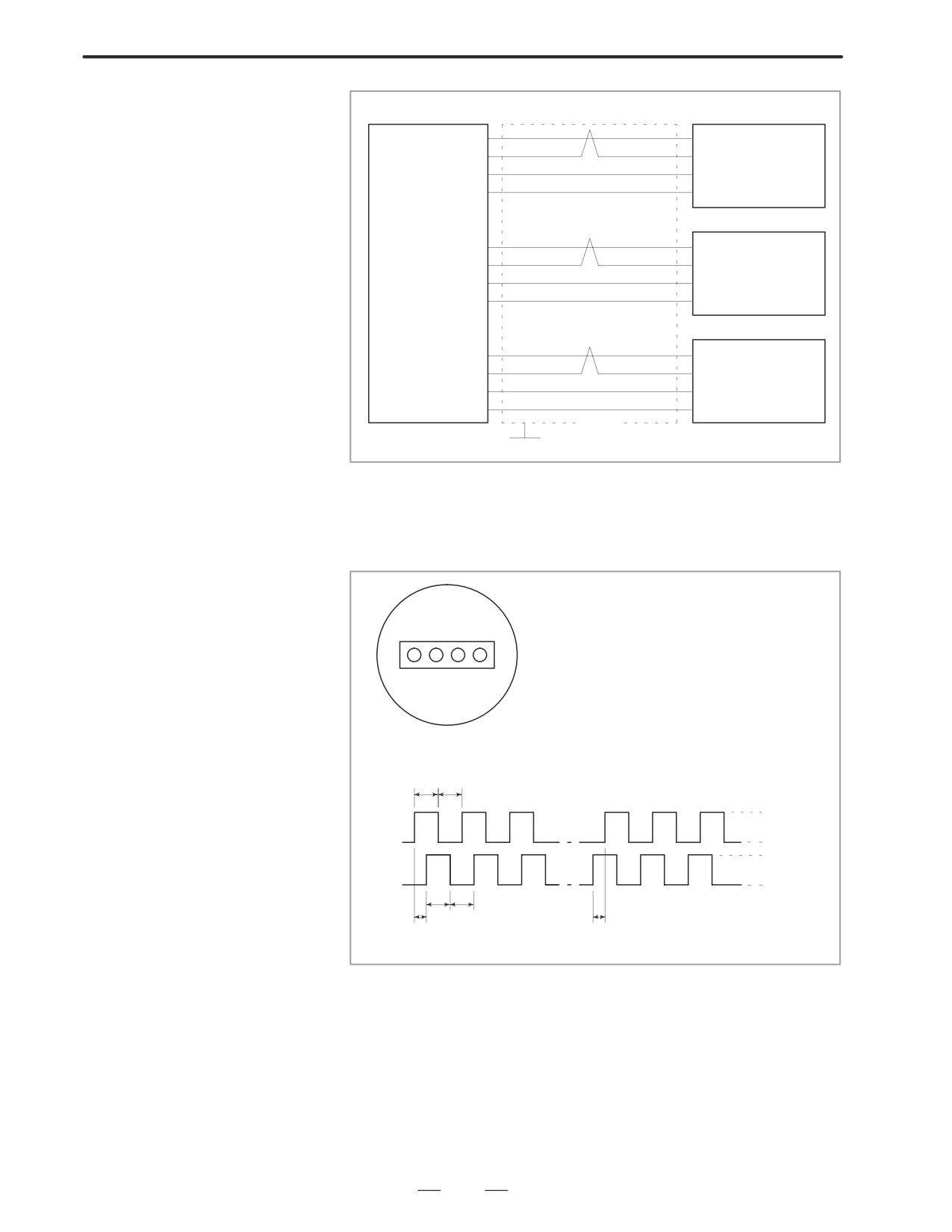
(a) Incorrect of cable
Check disconnection of cable or short circuit.
Main CPU board
MPG (JA3)
1st MPG
#1
2nd MPG
#2
3rd MPG
#3
315
7. TROUBLESHOOTING
B-63005EN/01
Manual pulse
CNC side MPG (JA3)
generator
HA1
(03)
(05)
HA1
1st
HB1
(02)
(06)
HB1
+5V
(09)
(03)
+5V
0V
(12)
(04)
0V
HA2
(03)
(05)
HA2
2nd
HB2
(04)
(06)
HB2
+5V
(18)
(03)
+5V
0V
(14)
(04)
0V
HA3
(05)
(05)
HA3
3rd
HB3
(06)
(06)
HB3
+5V
(20)
(03)
+5V
0V
(16)
(04)
0V
shield
Connector:half pitch
20pins (HIROSE)
G
(b) Manual pulse generator is faulty
When you rotate the MPG, the following signal is output.
Measure the signal with synchroscope at screw terminal on back of
MPG. If no signal is output, measure +5V voltage.
Back of MPG
Screw terminal
HA: A phase signal
HB: B phase signal
+5V 0V HA HB
Rotation in plus
Rotation in minus
1:1
+5V
HA
on
off
on
off
0V
+5V
HB
on
off
on
off
0V
1:1
1/4 phase difference
1/4 phase difference
Check on and off ratio and phase difference of HA and HB.
316
B-63005EN/01
7.TROUBLESHOOTING
7.5
AUTOMATIC
OPERATION
CANNOT BE DONE
Points
(1) Check manual operation is possible.
(2) Check the status of cycle start LED on machine operator’s manual.
(3) Check status of CNC.
Causes and Remedies
When manual operation is either impossible, perform countermeasure,
based on the previous item ”Jog operation cannot be done”.
Confirm that a correct mode is selected according to the mode select status
of CNC status display. Also, by confirming the automatic operation
status it is possible to identify cycle operation, feed hold and cycle stop
state.
1. When cycle operation is
“****” is displayed at status display on CRT.
not started (Cycle start
(1) Mode select signal is not correct.
LED does not light)
When the mode select signal is input correctly, following status
display is done.
MDI
:Manual data input mode (MDI)
MEM :Memory operation mode
RMT
:Remote operation mode
If status display does not show a correct status, check the mode signal
with following diagnosis function of PMC side (PMCDGN).
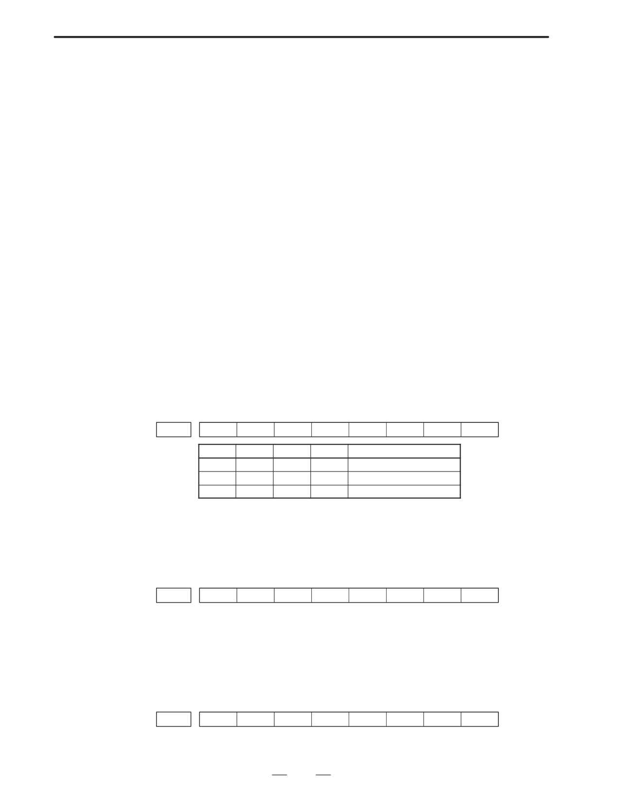
#7
#6
#5
#4
#3
#2
#1
#0
G0043
DNCI
MD4
MD2
MD1
DNCI
MD4
MD2
MD1
Mode select
–
0
0
0
Manual data input mode
0
0
0
1
Memory operation mode
1
0
0
1
Remote operation mode
(2) Cycle start signal is not input
This signal turns 1 when cycle start button is pressed and turns 0 when
it is released. The cycle start actuates when it changes from 1 to 0.
Check the state of the signal using PMC’s diagnostic
function(PMCDGN).
#7
#6
#5
#4
#3
#2
#1
#0
G0007
ST
#2 (ST)
: Cycle start signal
(3) Feed hold signal is input
Under normal state, the feed hold signal is 1 when the feed hold button
is not pressed.
Check the state of this signal using the PMC’s diagnostic function
(PMCDGN) .
#7
#6
#5
#4
#3
#2
#1
#0
G0008
*SP
#5 (*SP)
: Feed hold signal
317
7. TROUBLESHOOTING
B-63005EN/01
2. When an automatic
CNC’s status display shows “STRT” on the CRT.
operation is in progress
(1) Check the contents of diagnostic nos. 000 to 015.
(Cycle start LED is lit)
No. Message
Display
a.
000
WAITING FOR FIN SIGNAL
: 1(Example)
b.
001
MOTION
: 0
c.
002
DWELL
: 0
d.
003
IN-POSITION CHECK
: 0
e.
004
FEEDRATE OVERRIDE 0%
: 0
f.
005
INTERLOCK / START LOCK
: 0
g.
006
SPINDLE SPEED ARRIVAL CHECK
: 0
010
PUNCHING
: 0
011
READING
: 0
012
WAITING FOR (UN) CLAMP
: 0
h.
013
JOG FEEDRATE OVERRIDE 0%
: 0
i.
014
WAITING FOR RESET, ESP, RRW OFF
: 0
015
EXTERNAL PROGRAM NUMBER SEARCH
: 0
Items with a to i relate with an automatic operation and their details
are as follows :
a. An auxiliary function is
An auxiliary function (M/S/T/B) specified in a program is not ended.
being executed (waiting
Check according to the following procedure.
for FIN signal)
At first, confirm the kind of interface of an auxiliary function.
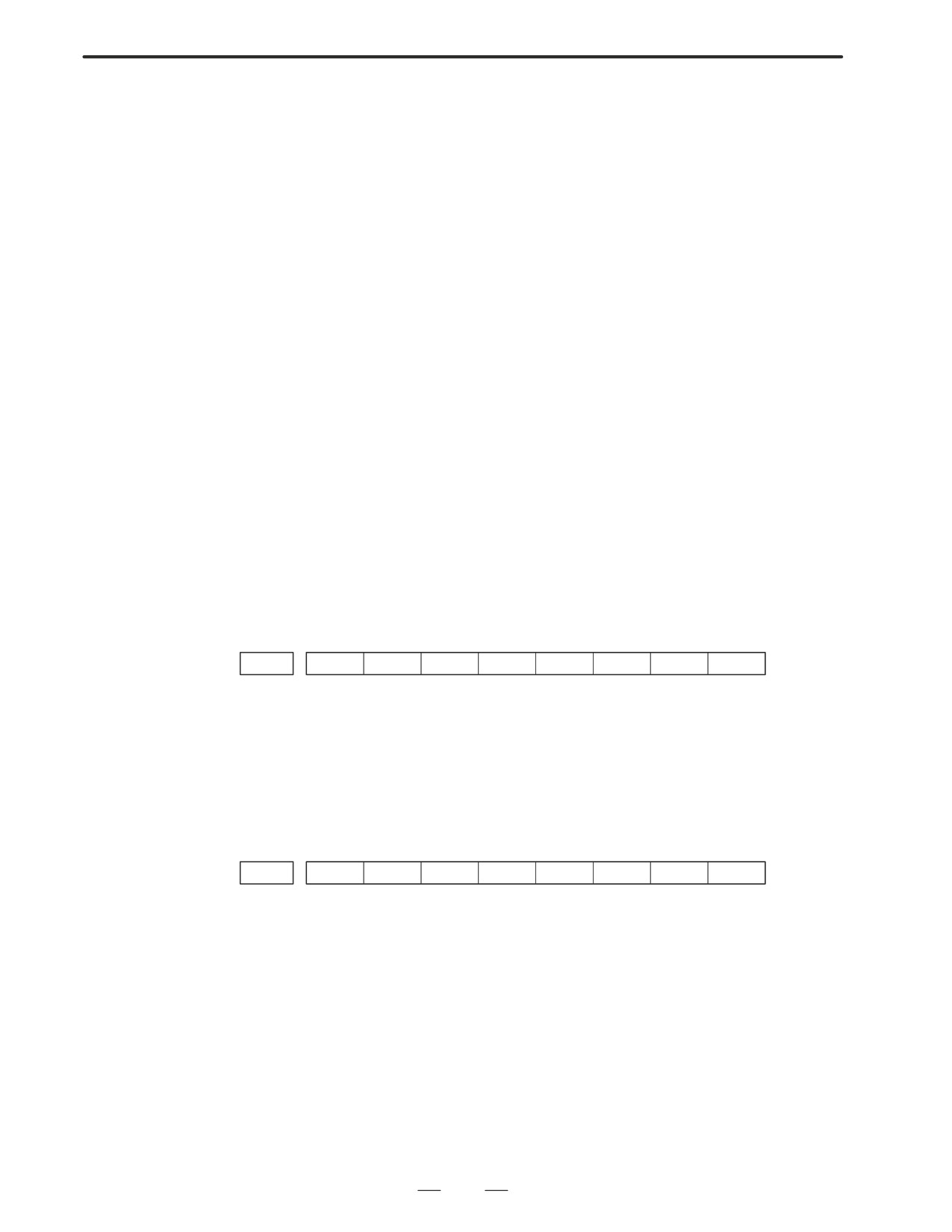
#7
#6
#5
#4
#3
#2
#1
#0
3001
HSIF
#7(HSIF)
0 : M/S/T/B is of normal interface.
1 : M/S/T/B is of high-speed interface.
1) Normal interface
When the auxiliary function finish signal turns from 1 to 0, the
auxiliary function is supposed to be ended and the next block is read
for operation. Confirm the status of this signal using PMC’s
diagnostic function(PMCDGN).
#7
#6
#5
#4
#3
#2
#1
#0
G0004
FIN
#3 (FIN)
: Auxiliary function finish signal
2) High-speed interface
The auxiliary function is supposed to be ended when the signals are
in the following state. Confirm it using PMC’s diagnostic function
(PMCDGN).
318
B-63005EN/01
7.TROUBLESHOOTING
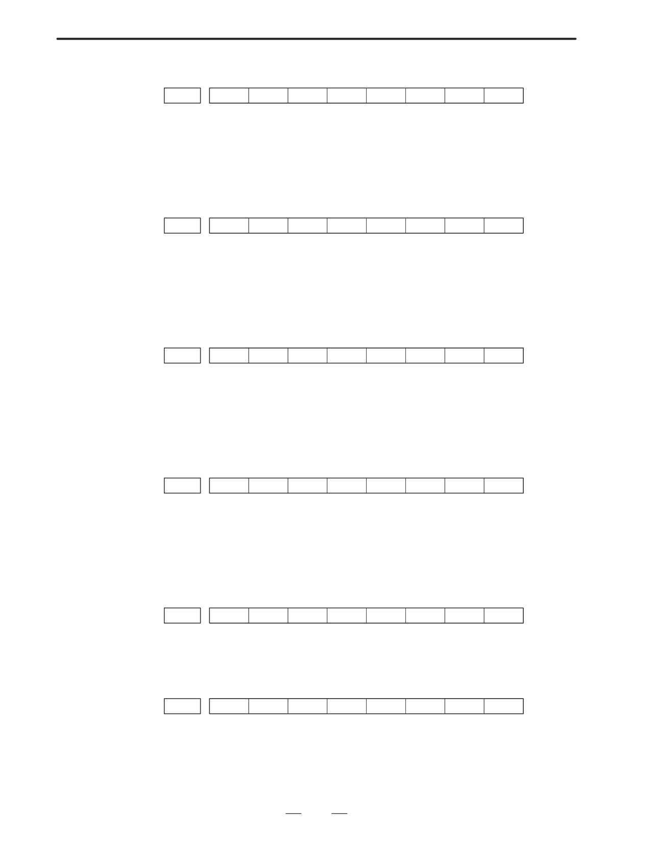
<M series>
#7
#6
#5
#4
#3
#2
#1
#0
G0005
BFIN
TFIN
SFIN
MFIN
#0(MFIN)
: M function finish signal
#2(SFIN)
: S function finish signal
#3(TFIN)
: T function finish signal
#4(BFIN)
: 2nd auxiliary function finish signal
#7
#6
#5
#4
#3
#2
#1
#0
F0007
BF
TF
SF
MF
#0(MF)
: M function strobe signal
#2(SF)
: S function strobe signal
#3(TF)
: T function strobe signal
#7(BF)
: 2nd auxiliary function strobe signal
<T series>
#7
#6
#5
#4
#3
#2
#1
#0
G0005
BFIN
TFIN
SFIN
MFIN
#0(MFIN)
: M function completion signal
#2(SFIN)
: S function completion signal
#3(TFIN)
: T function completion signal
#4(BFIN)
: Second auxiliary function completion signal
#7
#6
#5
#4
#3
#2
#1
#0
F0007
BF
TF
SF
MF
#0(MF)
: M function strobe signal
#2(SF)
: S function strobe signal
#3(TF)
: T function strobe signal
#4(BF)
: Second auxiliary function strobe signal
<M/T series>
#7
#6
#5
#4
#3
#2
#1
#0
G0004
MFIN3
MFIN2
#4(MFIN2)
: Second M function completion signal
#5(MFIN3)
: Third M function completion signal
#7
#6
#5
#4
#3
#2
#1
#0
G0008
MF3
MF2
#4(MF2)
: Second M function strobe signal
#5(MF3)
: Third M function strobe signal
* The second and third M functions are enabled only when bit 7 (M3B)
of parameter No. 3404 is set to 1.
319